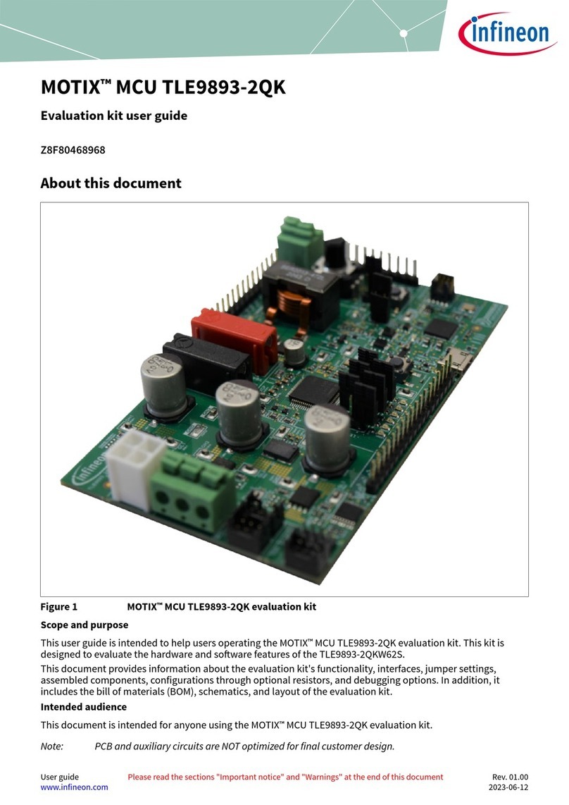
User manual for TDM3885 evaluation board
4 A synchronous buck voltage regulator with integrated inductor
About this document
Scope and purpose
The TDM3885 4 A point-of-load (POL) module is an easy-to-use, fully integrated and highly efficient DC-DC
module. The module’s pulse width modulation (PWM) controller, MOSFETs and inductor make TDM3885 a
space-efficient solution, providing accurate power delivery. The TDM3885 employs an enhanced stability
engine that makes it stable with ceramic capacitors without compensation.
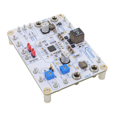
This user manual contains the schematic and bill of materials (BOM) for the EVAL_TDM3885_3.3Vout
engineering evaluation board. The guide describes operation and use of the evaluation board itself. Detailed
application information for TDM3885 is available in the TDM3885 datasheet.
Intended audience
This document is intended as a guide for design engineers evaluating the performance of TDM3885 with the
engineering EVAL_TDM3885_3.3Vout demo board.
Table of contents
About this document....................................................................................................................... 1
Scope and purpose ......................................................................................................................... 1
Intended audience.......................................................................................................................... 1
Table of contents............................................................................................................................ 1
1Board information.................................................................................................................. 2
1.1 Board picture and overview....................................................................................................................2
1.2 Board features.........................................................................................................................................2
1.3 Connections and operating instructions................................................................................................3
1.4 Power-on procedure ...............................................................................................................................4
1.5 PCB layout ...............................................................................................................................................5
1.6 Schematic................................................................................................................................................8
1.7 Bill of materials........................................................................................................................................9
2Typical operating waveforms .................................................................................................10
2.1 PVin = 5 V..................................................................................................................................................10
2.2 PVin = 12 V................................................................................................................................................11
Revision history.............................................................................................................................17


