Infineon ESD0P2RF-02LS User manual

RF and Protection Devices
ESD TVS Diodes
Agilent ADS Design Kit Manual
Revision: 1.0.4 - October 7, 2011

Edition 2009.11.16
Published by
Infineon Technologies AG
81726 Munich, Germany
© 2010 Infineon Technologies AG
All Rights Reserved.
Legal Disclaimer
The information given in this document shall in no event be regarded as a guarantee of conditions or
characteristics. With respect to any examples or hints given herein, any typical values stated herein and/or any
information regarding the application of the device, Infineon Technologies hereby disclaims any and all
warranties and liabilities of any kind, including without limitation, warranties of non-infringement of intellectual
property rights of any third party.
Information
For further information on technology, delivery terms and conditions and prices, please contact the nearest
Infineon Technologies Office (www.infineon.com).
Warnings
Due to technical requirements, components may contain dangerous substances. For information on the types in
question, please contact the nearest Infineon Technologies Office.
Infineon Technologies components may be used in life-support devices or systems only with the express written
approval of Infineon Technologies, if a failure of such components can reasonably be expected to cause the
failure of that life-support device or system or to affect the safety or effectiveness of that device or system. Life
support devices or systems are intended to be implanted in the human body or to support and/or maintain and
sustain and/or protect human life. If they fail, it is reasonable to assume that the health of the user or other
persons may be endangered.


ESD TVS Diodes
Agilent ADS Design Kit Manual
1 Introduction
Infineon’s TVS design kit is intended to support designers used Agilent Advanced Design System (ADS) software for
circuit design. It contain models of ESD TVS diodes and all necessary parts to use these models. Device models also
include in-package parasitic components, such as bond wire inductances, resistances, etc. Tab. 1shows currently
supported devices.
Table 1: Supported devices
Type Package Basic Description
ESD0P2RF-02LS TSSLP-2-1 ESD 1x Bi-directional Ultra Low Capacitance TVS Diode
ESD0P2RF-02LRH TSLP-2-17 ESD 1x Bi-directional Ultra Low Capacitance TVS Diode
ESD3V3U4ULC TSLP-9-1 ESD 4x Uni-directional Ultra Low Capacitance TVS Diode Array
ESD5V3U2U-03LRH TSLP-3-7 ESD 2x Uni-directional Ultra Low Capacitance TVS Diode Array
ESD5V3U2U-03F TSFP-3 ESD 2x Uni-directional Ultra Low Capacitance TVS Diode Array
ESD5V3U4U-HDMI TSLP-9-1 ESD 4x Uni-directional Ultra Low Capacitance TVS Diode Array
ESD18VU1B-02LS TSSLP-2-1 ESD 1x Bi-directional Ultra Low Capacitance TVS Diode
ESD18VU1B-02LRH TSLP-2-17 ESD 1x Bi-directional Ultra Low Capacitance TVS Diode
ESD5V3L1B-02LS TSSLP-2-1 ESD 1x Bi-directional TVS Diode
ESD8V0R1B-02EL TSLP-2-18 ESD 1x Bi-directional Low Capacitance TVS Diode
ESD8V0R1B-02ELS TSSLP-2-2 ESD 1x Bi-directional Low Capacitance TVS Diode
Infineon Technologies AG Page 4 of 8 Rev. 1.0.4 - October 7, 2011

ESD TVS Diodes
Agilent ADS Design Kit Manual
2 Installation
Infineon’s TVS design kit is delivered as a single zip archive, which contain all necessary structures necessary for
Agilent ADS. The package can be installed anythere in your system. In this manual the "USER_LEVEL" installation
level is used since it is simple and do not require additional system administrative privilegies. For installation it is
recommended to use "ADS Design Kit Tools". Start ADS as usual and select "DesignKit" pull-down menu from the
main ADS window. Select "Install Design Kits. . . " submenu and then press "Unzip Design Kit Now. . . " button in the
empty Design Kit setup form (Fig. 1). Fill in the path to design kit zip file and path for installation directory like it shown
in Fig. 3. The filled "Install Design Kits. . . " (Fig. 2) should appear. Please check that there are no errors occured
during installation process. The problematic fields will be highlighted in a red color. After performing the above
steps design kit is ready to work. More information about ADS design kit management can be obtained from ADS
documentation:
http://edocs.soco.agilent.com/display/ads2009U1/Design+Kit+Installation+and+Setup
Figure 1: "Install Design Kits. . . " empty form Figure 2: "Install Design Kits. . . " filled form
Figure 3: Unzip design kit.
Infineon Technologies AG Page 5 of 8 Rev. 1.0.4 - October 7, 2011

ESD TVS Diodes
Agilent ADS Design Kit Manual
3 Using Design Kit
After installation steps design kit is ready to use. The "Infineon TVS" components palette (Fig. 4) appear at the first
position of the palette list. It contain listed in Sect. 1components. They can be placed like any other ADS component
in the schematic. If any Infineon component was used, it is necessary to place also "Infineon Netlist Include" (Fig. 5)
component otherwise simulator will report error. Components do not have any parameters, and component name
correspond to part and package description.
Figure 4: Infineon ADS palette Figure 5: Infineon Netlist Include component
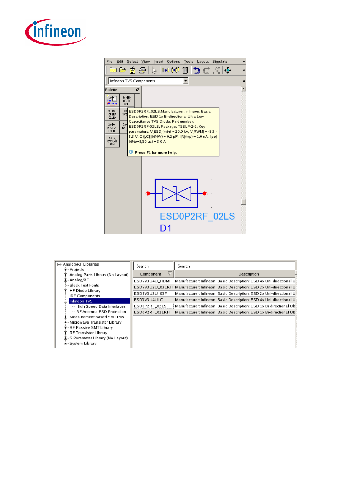
There are two ways to place Infineon components in the schematic: using palette(Fig. 6) and using components
library(Fig. 7). The component library can be called through Insert->Component->Component Library menu. Both
ways are supported by Infineon’s design kit and both provide a brief device information for the designer.
Infineon Technologies AG Page 6 of 8 Rev. 1.0.4 - October 7, 2011
ESD TVS Diodes
Agilent ADS Design Kit Manual
Figure 6: Placement using component palette
Figure 7: Placement using component library
Infineon Technologies AG Page 7 of 8 Rev. 1.0.4 - October 7, 2011

w w w . i n f i n e o n . c o m
Published by Infineon Technologies AG
This manual suits for next models
10


