Infineon XMC4800 User manual
User Manual R1.0
www.infineon.com
2016
-
04
-
15
UG_201604_PL30_017
For XMC4000 family
About this document
Scope and purpose
This document provides a hardware description of the XMC4800 IoT Amazon FreeRTOS Connectivity kit with
EtherCAT® including schematics and list of material. For fast software development you can find the mapping of
XMC4800 functions to the on-board components in various tables.
Intended audience
This document is intended for anyone who wants to develop software on the XMC4800 IoT Amazon FreeRTOS
Connectivity kit with EtherCAT® or wants to use this kit for evaluating and demonstrating the capabilities of the
XMC4800 microcontroller.
Table of contents
About this document.................................................................................................................................................................................. 1
Table of contents......................................................................................................................................................................................... 1
1 Introduction ......................................................................................................................................................................... 2
1.1 Key features ......................................................................................................................................................................... 2
1.2 Block diagram ..................................................................................................................................................................... 3
2 Hardware description....................................................................................................................................................... 4
2.1 Power supply....................................................................................................................................................................... 4
2.2 Arduino compatible connector .................................................................................................................................... 5
2.3 mikroBUS™socket ............................................................................................................................................................ 7
2.4 User push buttons and user LEDs............................................................................................................................... 8
2.5 Debugging and UART-to-USB communication...................................................................................................... 8
2.5.1 On-board debug probe.............................................................................................................................................. 8
2.5.2 Cortex® debug connector (10-pin)..................................................................................................................... 8
2.6 Reset........................................................................................................................................................................................ 9
2.7 CAN transceiver.................................................................................................................................................................. 9
2.8 Phy-2-Phy EtherCAT® connection ............................................................................................................................ 9
3 Production data.................................................................................................................................................................11
3.1 Schematics..........................................................................................................................................................................11
3.2 Components placement and geometry...................................................................................................................16
3.3 Bill of material...................................................................................................................................................................16
Revision history.........................................................................................................................................................................................19

User Manual 2 R1.0
2016
-
04
-
15
Introduction
XMC4800 IoT Amazon FreeRTOS Connectivity kit WiFi with EtherCAT® Kit
For XMC4000 family
1 Introduction
This document describes the features and hardware details of the XMC4800 IoT Amazon FreeRTOS Connectivity kit
with EtherCAT® equipped with an ARM® Cortex®-M4 based XMC microcontroller from Infineon Technologies AG.
It can be used with a wide range of development tools including Infineon’s free of charge Eclipse based IDE DAVE . The
XMC4800 IoT Amazon FreeRTOS Connectivity kit with EtherCAT® is designed to evaluate the capabilities of the
XMC4800 microcontroller especially in EtherCAT® slave applications. Table 1 shows the kit specification.
This kit includes the WiFi module mikroBUS from MikroElektronica based on ESP-WROOM-02 device. More
Information about this module can be found here.
Table 1 Kit specification
Processor
Infineon’s ARM® Cortex®
-
M4 XMC48
00
m
icrocontroller
running at 144
MHz
in LQFP100 package (order nu
mber XMC48
00
-
F100
K2
048
AA
)
RAM
m
emory
352
kB
yte SRAM
Flash
m
emory
2 M
B
of Flash
Di
mensions
75 x 138 mm (91 x 144
mm with connectors
incl.
Phy
-
2
-
P
hy
)
Clock
c
rystals
12 MHz and 32.768 kHz crystal for CPU
Power
•
Via
USB
c
onnector
(Micro
-
AB USB)
or
•
Via On
-
Board Debugger (Micro
-
AB USB)
Connectors
•
EtherCAT®
Slave
IN and OUT interface vi
a RJ45 jack
•
mi
k
roBUS
™
socket
(2x8
-
pin)
•Arduino compatible connectors (1x10-pin, 2x8-pin, 1x6pin, 2x3pin)
•USB connector (Micro-AB USB)
•CAN connector (D-Sub DE-9)
•EtherCAT® Phy-2-Phy connector (not assembled)
•
Serial Wire Debug interface (2x5, 50 mil pitch) t
o XMC™
(not assembled)
(on board debugger can be overridden by externally connected debugger)
Debugger
On
-
Board J
-
Link debug probe via USB supporting
•
Serial Wire Debug (SWD)
•
UART
-
to
-
USB bridge (virtual COM)
Others
•
On
-
board debug probe, based on XMC4200
m
icrocontroller
•
2x
EtherCAT®
Phys
•CAN transceiver
•2 user push-buttons,
•
2 user LEDs
•
Reset push
-
button
1.1 Key features
The XMC4800 IoT Amazon FreeRTOS Connectivity kit with EtherCAT® has the following key features and components:
•XMC4800 microcontroller (ARM® Cortex®-M4 based), 144 MHz, 2MB Flash, 352 kB SRAM, LQFP100 package
•On-board debug probe with USB interface supporting SWD + SWO
•Virtual COM port via on-board debug probe
•EtherCAT® slave components: 2 EtherCAT® phys and 2 RJ45 jacks
•Prepared for EtherCAT® Phy-2-Phy connection for backplane applications (assembly option)
•Arduino compatible connector and voltage level shifter for 3.3 V / 5 V Arduino shields
•mikroBUS™socket for plug-and-play click boards™
•CAN transceiver and CAN connector (D-Sub DE-9)

User Manual 3 R1.0
2016
-
04
-
15
Introduction
XMC4800 IoT Amazon FreeRTOS Connectivity kit WiFi with EtherCAT® Kit
For XMC4000 family
•USB interface (Micro-AB USB plug)
•Voltage regulator 5 V -> 3.3 V
•2 x User push-buttons
•2 x User LED
•Reset push-button
•12 MHz crystal
•32.768 kHz RTC crystal
1.2 Block diagram
The block diagram in Figure 1 shows the main components of the XMC4800 IoT Amazon FreeRTOS Connectivity kit
with EtherCAT® and their interconnections. There are following main building blocks:
•XMC4800 microcontroller in a LQFP100 package
•On-board USB debug probe based on XMC4200 for SWD, SWV and Virtual COM port support
•2 EtherCAT® Phy with 2 RJ45 plugs
•Connection Header for Arduino
•mikroBUS™socket
•2 User push-buttons, 2 User LEDs, Reset push-button
•Micro-AB USB Plug
•CAN transceiver
Figure 1 Block diagram of the XMC4800 IoT Amazon FreeRTOS Connectivity kit with EtherCAT®
User Manual 4 R1.0
2016
-
04
-
15
Hardware description
XMC4800 IoT Amazon FreeRTOS Connectivity kit WiFi with EtherCAT® Kit
For XMC4000 family
2 Hardware description
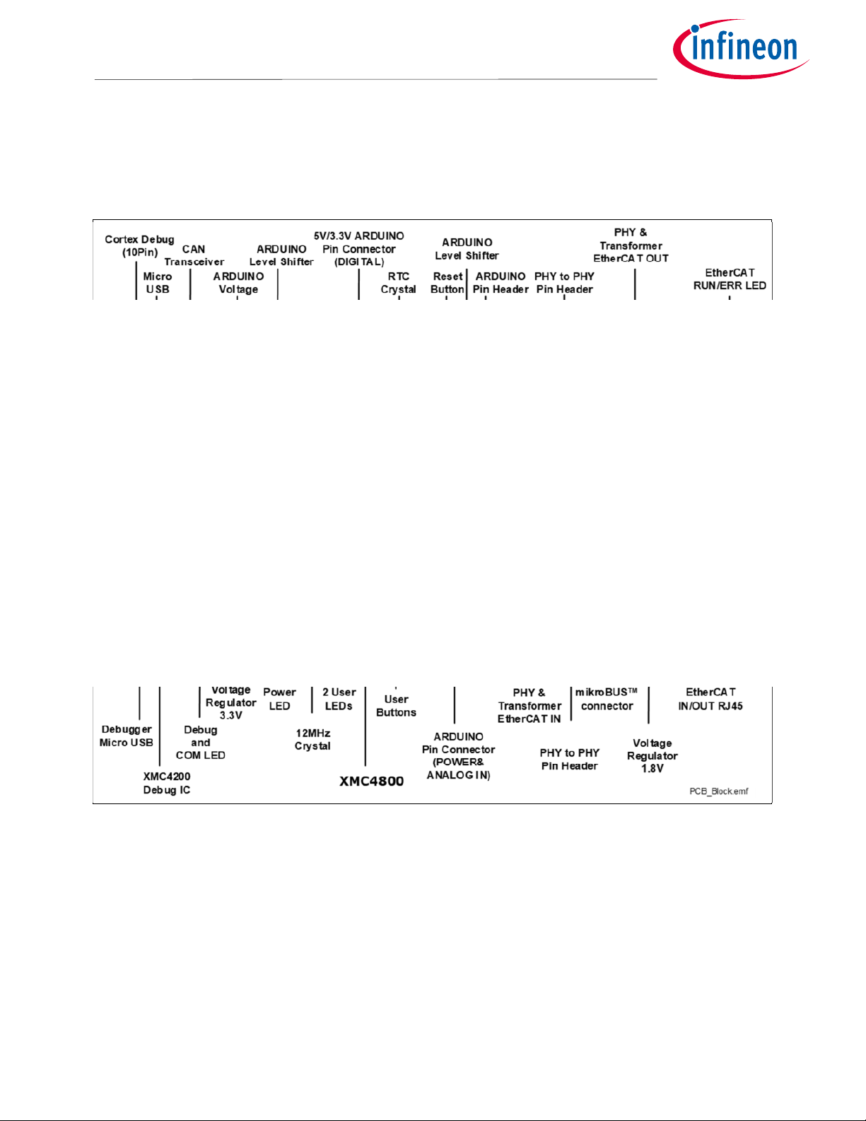
The following chapters provide a detailed description of the hardware and how it can be used. The hardware is
depicted in Figure 2.
Figure 2 PCB of the XMC4800 IoT Amazon FreeRTOS Connectivity kit with EtherCAT®
2.1 Power supply
The XMC4800 IoT Amazon FreeRTOS Connectivity kit with EtherCAT® must be supplied by an external 5 volt DC
power supply connected to any of the micro USB plugs (X100, X101). Out of the box with the pre-programmed
EtherCAT® slave application and the on-board debug probe in operation, the XMC4800 IoT Amazon FreeRTOS
Connectivity kit with EtherCAT® typically draws about 440 mA in an EtherCAT® environment. This current can be
delivered via the USB plug of a PC, which is specified to deliver up to 500 mA. The green Power LED (VDD3.3) indicates
the presence of the generated 3.3 V supply voltage.
On-board reverse current protection diodes will ensure safe operation when power is provided through both USB plugs
at the same time. These protection diodes allows to use the on-board debug probe connected with a PC/Notebook via
X101 and a second host PC/Laptop connected with the XMC4800 IoT Amazon FreeRTOS Connectivity kit with
EtherCAT® via X100.

User Manual 5 R1.0
2016
-
04
-
15
Hardware description
XMC4800 IoT Amazon FreeRTOS Connectivity kit WiFi with EtherCAT® Kit
For XMC4000 family
If the board is powered via a USB plug, it is not recommended to apply an additional 5 Volt power supply to one of the 5
Volt power pins (VDD5, 5 V) on the Arduino headers or mikroBUS™socket, because there is no protection against
reverse current into the external power supply. These power pins can be used to power an external circuit, but care
must be taken not to draw more current than USB can deliver. A PC acting as a USB host can typically deliver up to 500
mA current. If higher currents are required and in order to avoid damage to the USB host, the use of an external USB
power supply which is able to deliver higher currents than 500 mA is strongly recommended.
After power-up the green DEBUG LED starts blinking. When there is a connection to a PC via the Debug USB plug X101
and the USB Debug Device drivers are installed on this PC, the DEBUG LED will turn from blinking to constant
illumination.
Figure 3 Power supply concept
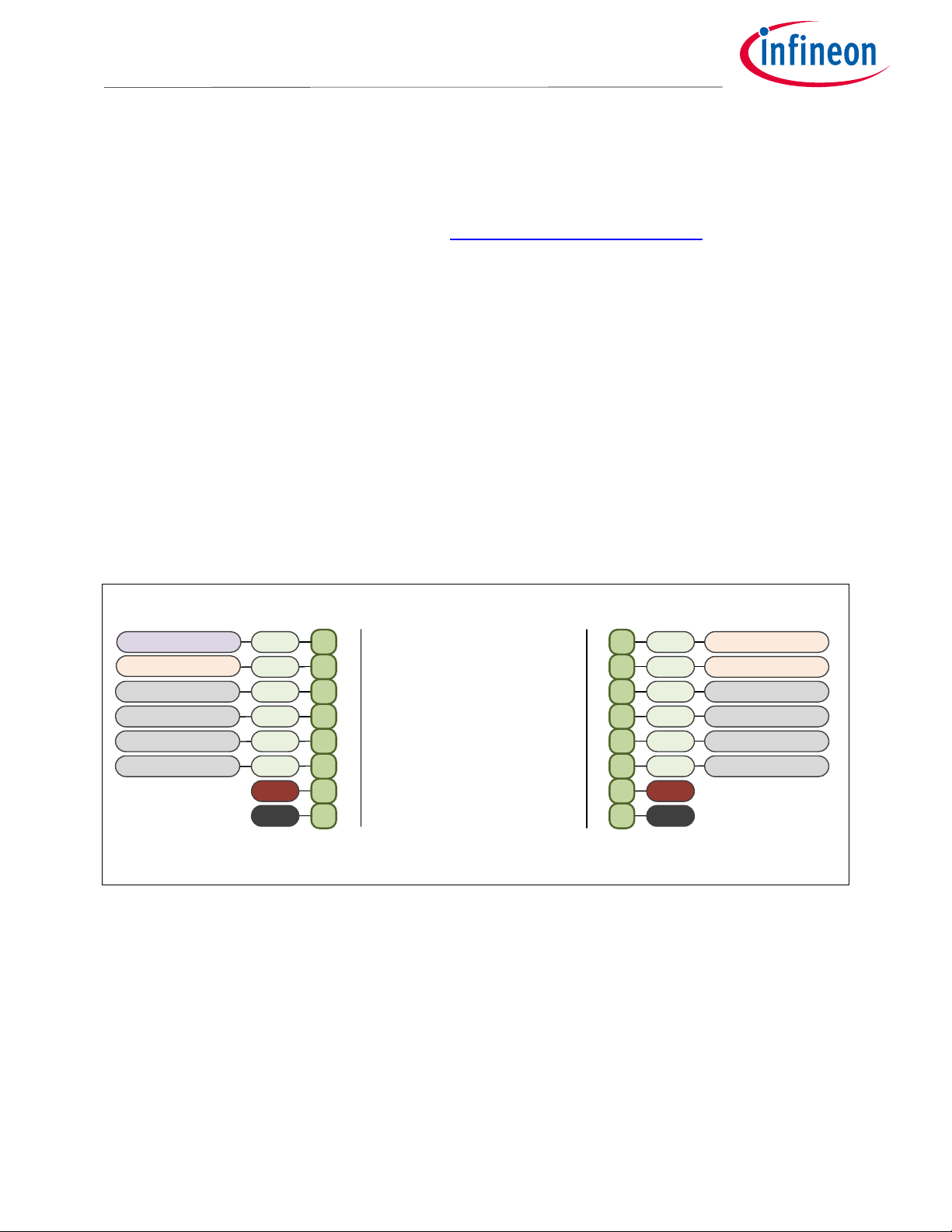
2.2 Arduino compatible connector
The mapping of GPIOs and XMC™pin functions to Arduino compatible functions can be found in Figure 4. The Arduino
compatible connector supports

User Manual 6 R1.0
2016
-
04
-
15
Hardware description
XMC4800 IoT Amazon FreeRTOS Connectivity kit WiFi with EtherCAT® Kit
For XMC4000 family
•SPI interface (SPI_xxx)
•I2C interface (I2C_xxx)
•UART interface (UART_xxx)
•PWM signal outputs (PWM0-5)
•ADC input (ADC0-5)
•Interrupt input (INT0-1)
•Reset
Figure 4 Mapping of Arduino™functions to XMC™pin functions
The XMC4800 IoT Amazon FreeRTOS Connectivity kit with EtherCAT® features a bi-directional voltage level shifter
and therefore supports 5 V Arduino shields as well as 3.3 V Arduino shields. Jumper JP300 (IOREF) determines whether
the Arduino shield is driven with 5 V or 3.3 V.
The analog input signals (ADC0-5) are limited to 3.3 V input voltage. A serial 100 Ohm resistor protects the analog
input pin against overcurrent.
Primarily, ADC0 to ADC3 should be used as analog inputs, because there is no additional circuit connected to these pins,
whereas ADC4 and ADC5 have additional circuitry and require an input signal with low input impedance (<500 Ohm).
Note:Parallel operation of I2C and ADC4 / ADC5 is not possible, because they share the same Arduino pins.
10
9P1.5/
P14.5 I2C_SDA: U0C0.DOUT0
P0.8/
P14.9 I2C_SCL: U0C0.SCLKOUT0
8VAREF
7GND
6P2.4 SPI_CLK: U0C1.SCLKOUT
P2.2 SPI_MISO: U0C1.DX0A
4P2.5 SPI_MOSI: U0C1.DOUT0 PWM5: CCU41.OUT0
3P1.14 SPI_CS: U0C1.SELO2 PWM4: CCU81.OUT10
2P0.6 PWM3: CCU80.OUT30
1P3.6 IO2: P3.6
8P15.9 IO1: P15.9
7P2.9 PWM2: CCU80.OUT22
6P2.7 PWM1: CCU80.OUT03
4P0.9 INT1: ERU0.1B0 PWM0: CCU40.OUT2
5P5.0 IO0: P5.0
3P0.7 INT0: ERU0.2B1
2P0.1 UART_TXD: U1C1.DOUT0
1P0.0 UART_RXD: U1C1.DX0D
1
3
2
4
P14.4
5
6
P14.9/
P0.8
P14.2
P14.1
P14.5/
P1.5
ADC3: VADC.G2CH0
ADC2: VADC.G1CH2
ADC1: VADC.G0CH1
ADC0: VADC.G0CH0 P14.0
7
GND
GND
5V
3V3
N.C.
RESET#
IOREF
N.C. 8
4
6
5
1
2
3
(Top View)
13
4
5
6
Arduino_Pin_Mapping.emf
ANALOG INPOWER
DIGITAL
5V
2
P3.9 SPI_CLK: U2C0.SCLKOUT
RESET#
GND
5
P3.7 SPI_MISO: U2C0.DX0C
P3.8SPI_MOSI: U2C0.DOUT0
PWM5: CCU41.OUT2
AREF: VAREF
I2C_SCL: U0C0.SCLKOUT0
I2C_SDA: U0C0.DOUT0
ADC5: VADC.G3CH3
ADC4: VADC.G2CH1
ADC5: VADC.G3CH3
ADC4: VADC.G2CH1
User Manual 7 R1.0
2016
-
04
-
15
Hardware description
XMC4800 IoT Amazon FreeRTOS Connectivity kit WiFi with EtherCAT® Kit
For XMC4000 family
2.3 mikroBUS™socket
This kit includes the WiFi module mikroBUS™from MikroElektronica based on ESP-WROOM-02 device. More
Information about this module can be found in the link: https://www.mikroe.com/wifi-esp-click
The mapping of GPIOs and XMC™pin functions to mikroBUS™functions can be found in Table 5. The mikroBUS™
connector supports
•SPI interface with one chip select (SPI_xxx)
•I2C interface (I2C_xxx)
•UART interface (UART_xxx)
•PWM signal output (PWM)
•ADC input (ADC)
•Interrupt input (INT)
•Reset (RST)
Attention:
Jumper JP300 (IOREF) must be set to 3.3 V (VDD3.3) when using click™boards. 5 V click™boards cannot be
used with the XMC4300 Relax EtherCAT® Kit.
Note:The mikroBUS™UART and debugger’s UART shares the same USIC channel (U1C0) of the XMC4800 device, but do
not share the same pins. Parallel operation by time multiplexing is possible.
Figure 5 Mapping of Arduino™functions to XMC™pin functions
1P2.8 PWM: CCU80.OUT32
2P3.5
3P2.15 UART_RXD: U1C0.DX0C
5P0.8 I2C_SCL: U0C0.SCLKOUT
4P2.14 UART_TXD: U1C0.DOUT0
6P1.5 I2C_SDA:U0C0.DOUT0
75V
8GND
7
8
4
6
5
1
2
3
(Top View)
mikroBUS_Pin_Mapping.emf
mikroBUS™
mikroBUS™
3V3
P2.5
P2.2
P2.4
P2.3
GND
P14.8
HIB_IO_0
ADC: VADC.G0CH0
RST: HIBOUT
SPI_CS: U0C1.SELO0
SPI_SCK: U0C1.SCLKOUT
SPI_MISO: U0C1.OUT01
SPI_MOSI: U0C1.DOUT0
INT: ERU0.3B1

User Manual 8 R1.0
2016
-
04
-
15
Hardware descri
ption
XMC4800 IoT Amazon FreeRTOS Connectivity kit WiFi with EtherCAT® Kit
For XMC4000 family
2.4 User push buttons and user LEDs
The XMC4800 IoT Amazon FreeRTOS Connectivity kit with EtherCAT® provides two push buttons and two LEDs. The
port pins used can be found in Table 2 and Table 3. These pins are used exclusively for this function and they are not
mapped to other devices or connectors.
Table 2
XMC48
00
pin m
apping
for u
ser LEDs
LED
XMC p
in
LED1
P4
.
0
LED2
P4.1
Table 3
XMC48
00 pin m
apping
for user push b
uttons
Button
XMC p
in
BUTTON1
P3.4
BUTTON2
HIB_IO_1
2.5 Debugging and UART-to-USB communication
The XMC4800 IoT Amazon FreeRTOS Connectivity kit with EtherCAT® supports debugging via 2 different channels:
•On-board debug probe
•10-pin Cortex® Debug connector (not assembled)
2.5.1 On-board debug probe
The on-board debug probe supports Serial Wire Debug (SWD) and UART communication. Both require the installation
of Segger’s J-Link Driver which is part of the DAVE™installation. DAVE™is a highly efficient development platform for
the XMC® microcontroller families to simplify and shorten software development. It can be downloaded at
www.infineon.com/dave. The latest Segger J-Link Driver can be downloaded at http://www.segger.com/jlink-
software.html. Table 4 shows the pin assignment of the XMC4800 used for debugging and UART communication.
Table 4
XMC4
8
00 p
ins
m
apping
for debugging and UART
-
c
ommunication
Pin
f
u
n
c
tion
Input/Output
XMC Pin
Data pin for
d
ebugging via SWD
I/O
TMS
Clock pin for
d
ebugging
v
ia SWD
O
TCK
Transmit pin for UART communication (PC_RX
D
)
O
P0.5
(U1
C0.DOUT
0
)
Receive pin for UART communication (PC_TX
D
)
I
P0.4
(U1C0.DX0A
)
2.5.2 Cortex® debug connector (10-pin)
The 10-pin Cortex® debug connector supports Serial Wire Debug (SWD) and Serial Wire Viewer (SWV). The pin
assignment of the Cortex® debug connector is shown in Table 5.
Table 5 Pin assignment of the Cortex® Debug Connector (X102)
Pin No.
Signal
n
ame
Description
1
VCC
+3.3 V
2
TMS
Serial Wire Data I/O
3
GND
Ground
4
TCK
Serial Wire Clock

User Manual 9 R1.0
2016
-
04
-
15
Hardware description
XMC4800 IoT Amazon FreeRTOS Connectivity kit WiFi with EtherCAT® Kit
For XMC4000 family
Pin No.
Signal
n
ame
Description
5
GND
Ground
6
SWV
Serial Wire Viewer (Trace Data Out)
7
Key
Key
8
NC
Not connected
9
GND_Detect
Ground det
ect
10
RESET
Rest (active low)
2.6 Reset
The reset pin (PORST#) of the XMC4800 is a bi-directional pin in open drain mode. An internal pull-up resistor keeps
the PORST# pin high during normal operation. A low level at this pin will force a hardware reset. In case of a MCU
internal reset the PORST# pin will drive a low signal.
A reset signal can be issued by
•the on-board Reset Button (SW102, “RESET”)
•the on-board debug probe (IC101.46)
•the external debugger connected to the 10-pin Cortex® debug probe connector (X102)
•the Arduino Power Header (RESET)
•the mikroBUS™socket (RST)
An XMC™internal circuit always ensures a safe Power-on-Reset. The XMC™does not require any additional external
components to generate a reset signal during power-up.
2.7 CAN transceiver
The XMC4800 IoT Amazon FreeRTOS Connectivity kit with EtherCAT® provides a CAN interface via a D-Sub DE-9
connector. Infineon’s high speed CAN transceiver {IFX1051LE) for industrial applications supports 3.3V I/O logic and is
suitable for 12 V and 24 V bus systems with an excellent EMC performance. The CAN bus (signals CANH, CANL) are
terminated by a 120 Ohm resistor.
Table 6 CAN signals and XMC4800 pin mapping
Signal
n
ame
Pin no. at D
-
Sub DE
-
9
(X400
)
XMC Pin, XMC
f
unction
CANH
X400.7
-
CANL
X400.2
-
CAN_TX
-
P2.0, CAN.N0
_TXD
CAN_RX
-
P14.3, CAN.N0_RXDB
GND
X400.3, X400.6
-
VDD5
X400.9 (needs to be connected
-
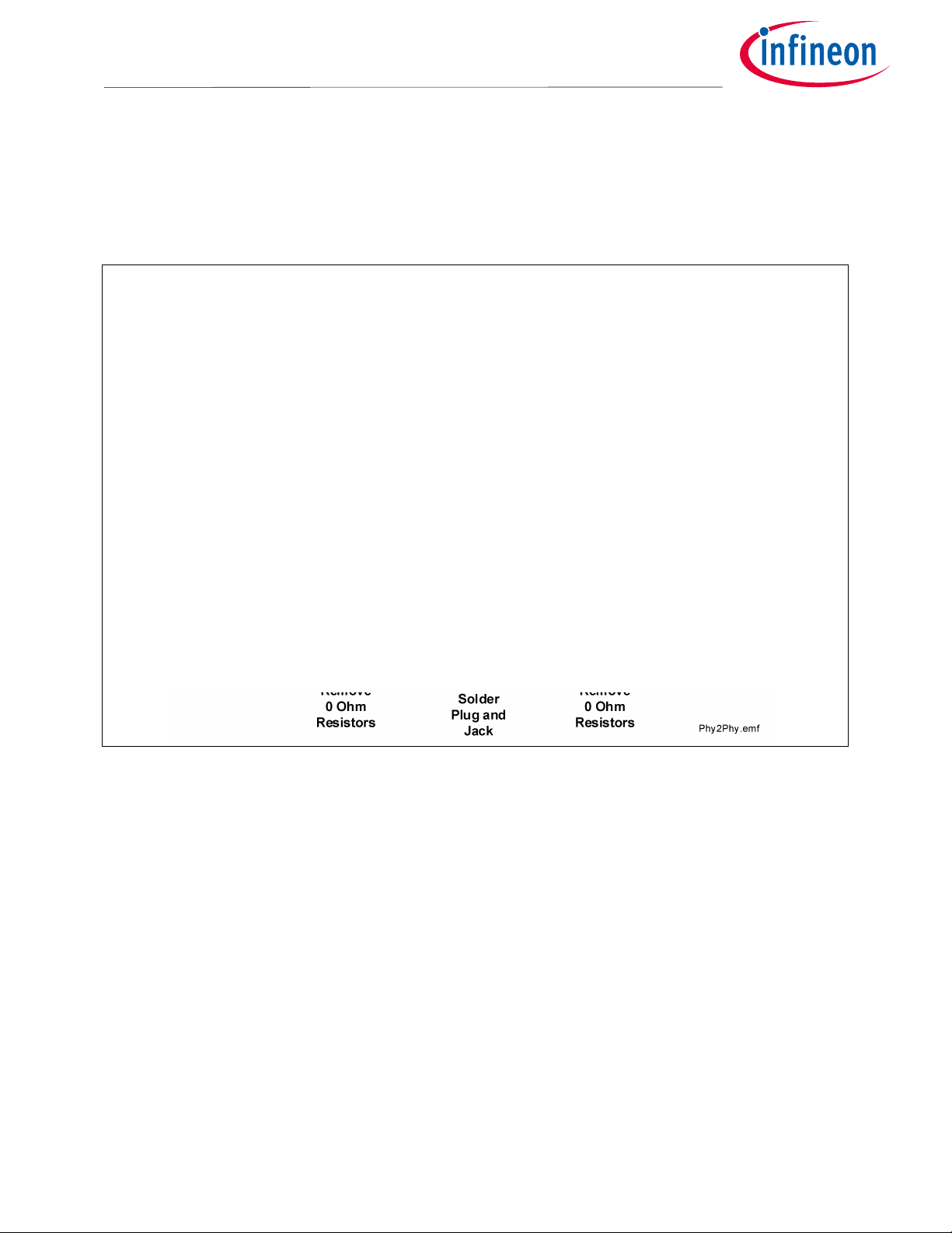
2.8 Phy-2-Phy EtherCAT® connection
For backplane/mid-plane oriented EtherCAT® applications, communication can be implemented without using
isolation transformers. Instead, low-cost ceramic capacitors can be used. The PCB layout of the XMC4800 IoT Amazon
FreeRTOS Connectivity kit with EtherCAT® has been prepared for EtherCAT® operation through direct Phy-2-Phy
connection.
For this purpose two XMC4800 IoT Amazon FreeRTOS Connectivity kit with EtherCAT® are required and some
modifications must be made to the kits (see Figure 6). All components required for this modification can be found
attached to the kit.
User Manual 10 R1.0
2016
-
04
-
15
Hardware description
XMC4800 IoT Amazon FreeRTOS Connectivity kit WiFi with EtherCAT® Kit
For XMC4000 family
•Remove four 0 Ohm resistors from each XMC4800 IoT Amazon FreeRTOS Connectivity kit with EtherCAT®
•Solder two 0 Ohm resistors onto each XMC4800 IoT Amazon FreeRTOS Connectivity kit with EtherCAT®
•Solder the connectors onto the XMC4800 IoT Amazon FreeRTOS Connectivity kit with EtherCAT®
After this modification EtherCAT® communication through the RJ45 is disabled.
Figure 6 Phy-2-Phy EtherCAT® connection between two XMC4800 IoT Amazon FreeRTOS Connectivity kit with
EtherCAT®

User Manual 11 R1.0
2016
-
04
-
15
Production data
XMC4800 IoT Amazon FreeRTOS Connectivity kit WiFi with EtherCAT® Kit
For XMC4000 family
3 Production data
This chapter covers schematics, board dimensions, component placement and the bill of material.
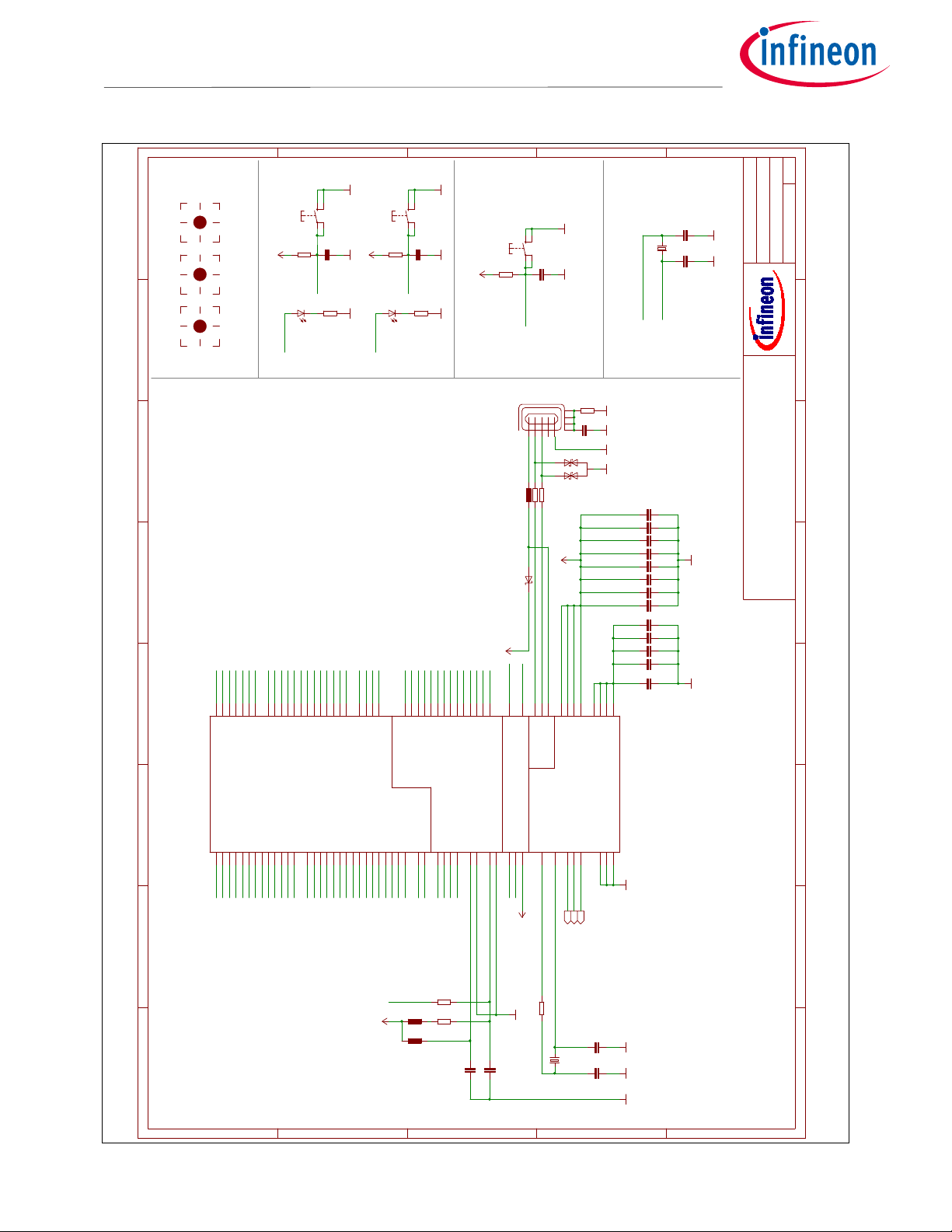
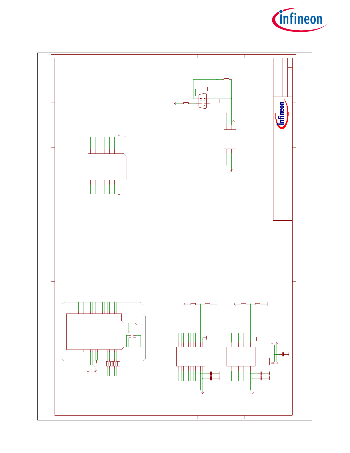
3.1 Schematics
The following figures show the schematics of the XMC4800 IoT Amazon FreeRTOS Connectivity kit with EtherCAT® in
hardware version 1.0:
•Figure 7: Schematic: MCU, Push Buttons, LEDs, Reset Button, Crystals, USB
•Figure 8: Schematic: EtherCAT® Phys, Magnetics, Phy-2-Phy
•Figure 9: Schematic: Arduino, mikroBUS, CAN
•Figure 10: Schematic: On-Board Debug Probe, Power Supply
User Manual 12 R1.0
2016
-
04
-
15
Production data
XMC4800 IoT Amazon FreeRTOS Connectivity kit WiFi with EtherCAT® Kit
For XMC4000 family
Figure 7 Schematic: MCU, Push Buttons, LEDs, Reset Button, Crystals, USB
100nF100nF
10uF/10V10uF/10V
10uF/10V10uF/10V
10uF/10V10uF/10V
10uF/10V10uF/10V
100nF100nF
100nF100nF
100nF100nF
100nF100nF
100nF100nF
100nF100nF
100nF100nF
100nF100nF
10uF/10V10uF/10V
100nF100nF
100nF100nF
15pF/040215pF/0402
15pF/040215pF/0402
100nF
100nF
10nF10nF
15pF15pF
15pF15pF
ESD8V0L2B-03LESD8V0L2B-03L
BAS3010A-03WBAS3010A-03W
GND
GND
GND
GND
GNDGND
GND
GND
GND GND
GND
GND
GNDGND GND
GND GND
GNDGND GNDGND
XMC4300_LQFP100
BLM18PG600BLM18PG600
BLM18PG600BLM18PG600
BLM18PG600BLM18PG600
LED-RT/D/0603LED-RT/D/0603
12MHZ/S/3.2X2.512MHZ/S/3.2X2.5
32.768KHZ32.768KHZ
1M1M
22R22R
22R22R
no ass./0R/0402no ass./0R/0402
0R/04020R/0402
510R/0402510R/0402
680R680R
10k10k
10K/0402
TMPS2-SMD
TMPS2-SMD
TMPS2-SMD
VDD3.3 VDD3.3
VDD3.3
VDD3.3
VDD3.3
VDD5
VDD3.3
ZX62-AB-5PAZX62-AB-5PA
ADJ_3 ADJ_4 ADJ_5
C100C100
C101C101
C102C102
C103C103
C104C104
C105C105
C106C106
C107C107
C108C108
C109C109
C110C110
C111C111
C112C112
C113C113
C114C114
C115C115
C116C116
C117C117
C118
C119
C120C120
C400C400
C401C401
D100 1
2
3
D100
D101
AC
D101
EPAD
EXP
HIB_IO_0
14 HIB_IO_1
13
P0.0
2P0.1
1P0.2
100 P0.3
99 P0.4
98 P0.5
97 P0.6
96 P0.7
89 P0.8
88 P0.9
4P0.10
3P0.11
95 P0.12
94
P1.0
79 P1.1
78 P1.2
77 P1.3
76 P1.4
75 P1.5
74 P1.6
83 P1.7
82 P1.8
81 P1.9
80 P1.10
73 P1.11
72 P1.12
71 P1.13
70 P1.14
69 P1.15
68
P2.0 52
P2.1 51
P2.2 50
P2.3 49
P2.4 48
P2.5 47
P2.6 54
P2.7 53
P2.8 46
P2.9 45
P2.10 44
P2.14 41
P2.15 40
P3.0 7
P3.1 6
P3.2 5
P3.3 93
P3.4 92
P3.5 91
P3.6 90
P4.0
85 P4.1
84
P5.0 58
P5.1 57
P5.2 56
P5.7 55
P14.0 31
P14.1 30
P14.2 29
P14.3 28
P14.4 27
P14.5 26
P14.6 25
P14.7 24
P14.8 37
P14.9 36
P14.12 23
P14.13 22
P14.14 21
P14.15 20
P15.2
19 P15.3
18 P15.8
39 P15.9
38
PORST#
65
RTC_XTAL_1 16
RTC_XTAL_2 15
TCK
67 TMS
66
USB_D+ 9
USB_D- 8
VAGND
32 VAREF
33
VBAT
17
VBUS 10
VDDA
35
VDDC 12
VDDC1 42
VDDC2 64
VDDC3 86
VDDP 11
VDDP1 43
VDDP2 60
VDDP3 87
VSS
59
VSSA
34
VSSO
63
XTAL1
61
XTAL2
62
IC100
L100L100
L101L101
L102L102
LED100LED101
Q100Q100
Q400Q400
R106R106
R107R107
R108R108
R109R109
R110R110
R111R111
R112R113
R114R115
R116
P
P1 S
S1
SW100
P
P1 S
S1
SW101
P
P1 S
S1
SW102
1
2
3
4
5
HIB_IO_0
HIB_IO_1
HIB_IO_1
P0.0
P0.1
P0.2
P0.3
P0.4
P0.5
P0.6
P0.7
P0.8
P0.9
P0.10
P0.11
P0.12
P1.0
P1.1
P1.2
P1.3
P1.4
P1.5
P1.6
P1.7
P1.8
P1.9
P1.10
P1.11
P1.12
P1.13
P1.14
P1.15
P2.0
P2.1
P2.2
P2.3
P2.4
P2.5
P2.6
P2.7
P2.8
P2.9
P2.10
P2.14
P2.15
P3.0
P3.1
P3.2
P3.3
P3.4
P3.4
P3.5
P3.6
P4.0
P4.0
P4.1
P4.1
P5.0
P5.1
P5.2
P5.7
P14.0
P14.1
P14.2
P14.3
P14.4
P14.5
P14.6
P14.7
P14.8
P14.9
P14.12
P14.13
P14.14
P14.15
P15.2
P15.3
P15.8
P15.9
RESET#
RESET#
RTC_XTAL_1
RTC_XTAL_1
RTC_XTAL_2
RTC_XTAL_2
TCK
TMS
USB_DM
USB_DP
VAREF
VBUS
VDDC
X100
D1
D2
A
B
C
D
E
1 2 3 4 5 6 7 8
A
B
C
D
E
1
2
3
4
5
6
7
8
XMC4300_Relax_v1.1
07.04.2016 13:25:56
1/4
Sheet:
Legal Disclaimer
The information given in this document shall in no event be regarded as a guarantee of conditions or
characteristics. With respect to anyexamples or hints given herein, any typical values stated herein and/or any
information regarding the application of the device, Infineon Technologies hereby disclaims any and all warranties
and liabilities of any kind, including without limitation, warranties of non-infringement of intellectual property rights
of any third party.
USB
Supply
Analog
Digital
Hibernate/RTC
XMC4300 Relax EtherCAT Kit
V1.1 / 02.2016
LED2 LED1
BUTTON 2
BUTTON 1
Reset
Buttons & LEDs
Target Device
RTC Crystal
USB Connector
2mA LED 2mA LED
ECAT0.P1_TXD3
ECAT0.P1_RX_ERRB
ECAT0.P1_TX_CLKA
ECAT0.P1_LINK_ACT
ECAT0.MDO/MDIA
ECAT0.P1_TXD2
ECAT0.P0_LINKB
ECAT0.P0_PHY_CLK25
ECAT0.P0_LINK_ACT
ECAT0.LED_RUN
ECAT0.LED_ERR
ECAT0.P0_RX_DVA
ECAT0.P0_TXD2
ECAT0.P0_TXD1
ECAT0.P0_TXD0
ECAT0.P0_RX_CLKA
ECAT0.P0_TXD3
ECAT0.P0_RXD0A
ECAT0.P0_TX_ENA
ECAT0.P0_TX_CLKA
ECAT0.MCLK
ECAT0.P1_TXD1
ECAT0.P1_TXD0
ECAT0.P1_TX_ENA
ECAT0.PHY_RST
ECAT0.P0_RX_ERRB
ECAT0.P0_RXD3B
ECAT0.P0_RXD2B
ECAT0.P0_RXD1B
ECAT0.P1_RX_DVB
ECAT0.P1_RXD3B
ECAT0.P1_RXD1B
ECAT0.P1_RXD2B
ECAT0.P1_RXD0B
ECAT0.P1_RX_CLKBECAT0.P1_LINKB
ECAT0.P1_RX_ERRB
MIKROBUS_RX
MIKROBUS_TX
MIKROBUS_AN
MIKROBUS_INT
CAN_TXD
CAN_RXD
SCL
SDA
MISO
SCK
MOSI
SWV
ARDUINO_PWM2
ARDUINO_PWM1
ARDUINO_UART_TX
ARDUINO_UART_RX
ARDUINO_SPI_CS, PWM4
ARDUINO_AN0
ARDUINO_AN1
ARDUINO_AN2
ARDUINO_AN3
ARDUINO_AN4
ARDUINO_AN5
MIKROBUS_SPI_CS
MIKROBUS_PWM
MIKROBUS_RST
LED1
LED2
BUTTON1
ARDUINO_IO2
ARDUINO_INT1, PWM0
ARDUINO_INT0
ARDUINO_PWM3
DEBUG_TX
DEBUG_RX
ARDUINO_IO0
ARDUINO_IO1
BUTTON2

User Manual 13 R1.0
2016
-
04
-
15
Production data
XMC4800 IoT Amazon FreeRTOS Connectivity kit WiFi with EtherCAT® Kit
For XMC4000 family
Figure 8 Schematic: EtherCAT® Phys, Magnetics, Phy-2-Phy
//m ucsdn 3 1 . eu.i nfi n e o n . c o m /Ro e m me l m /M y d oc u m ent s / Boot l o a d e r _ Rem a pp ing/ qrco de . bmp
//m ucsdn 3 1 .eu. inf i neon. com / Roem me l m /M yd o cum e n t s/Bo o t l oade r _ Rem a p p i ng/q r code. bmp
VDD1.8VDD1.8
VDD1.8VDD1.8
VDD1.8VDD1.8
VDD1.8VDD1.8
VDD3.3
VDD3.3
VDD3.3
VDD3.3
VDD3.3
VDD3.3
VDD3.3
VDD3.3
VDD3.3
100nF/50V/1206100nF/50V/1206
100nF/50V/1206100nF/50V/1206 100nF/50V/1206100nF/50V/1206
100nF/50V/1206100nF/50V/1206
100nF/50V/1206100nF/50V/1206
100nF/50V/1206100nF/50V/1206
1000pF/2kV/1206
100nF/0402100nF/0402
100nF/0402100nF/0402
100nF/0402100nF/0402
100nF/0402100nF/0402
100nF/0402100nF/0402
10uF/10V/080510uF/10V/0805
100nF/0402100nF/0402
100nF/0402
10uF/10V/080510uF/10V/0805
100nF/0402100nF/0402
100nF/0402100nF/0402
100nF/0402100nF/0402
1000pF/2kV/12061000pF/2kV/1206
100nF/50V/1206100nF/50V/1206
100nF/50V/1206100nF/50V/1206
100nF/0402
100nF/0402 100nF/0402
100nF/0402100nF/0402
100nF/0402100nF/0402
10uF/10V/080510uF/10V/0805
100nF/0402100nF/0402
100nF/0402100nF/0402
10uF/10V/080510uF/10V/0805
100nF/0402100nF/0402
100nF/0402100nF/0402
100nF/0402100nF/0402
100nF/0402100nF/0402
1000pF/2kV/1206
1000pF/2kV/12061000pF/2kV/1206
GNDGND
GND GND
GND
GND
GNDGNDGND GNDGNDGND
GNDGNDGND GNDGNDGND
GNDGND
GNDGND GNDGNDGND
GNDGND
GND
GND
GND
GND
GND
GNDGND GNDGNDGND GND
GND
GND
GND
BLM18PG600BLM18PG600
BLM18PG600BLM18PG600
PT61017PEL
PT61017PEL
no ass./0R/1206no ass./0R/1206
no ass./0R/1206no ass./0R/1206
no ass./0R/1206no ass./0R/1206
no ass./0R/1206no ass./0R/1206
0R/12060R/1206
0R/12060R/1206
0R/12060R/1206
0R/12060R/1206
75R/0603
75R/0603
75R/0603
75R/0603
49R9/060349R9/0603
49R9/060349R9/0603
49R9/060349R9/0603
49R9/060349R9/0603
1k24/0603
49R9/060349R9/0603
49R9/060349R9/0603
270R/0603270R/0603
270R/0603270R/0603
2k2/06032k2/0603
0R/12060R/1206
0R/12060R/1206
0R/12060R/1206
0R/12060R/1206
49R9/060349R9/0603
49R9/060349R9/0603
2k2/06032k2/0603
1k24/0603
49R9/060349R9/0603
49R9/060349R9/0603
49R9/060349R9/0603
49R9/060349R9/0603
270R/0603270R/0603
270R/0603270R/0603
75R/0603
75R/0603
75R/0603
75R/0603
680R/0603680R/0603
680R/0603680R/0603
4*49R94*49R9
4*49R94*49R9
4*49R94*49R9
4*49R94*49R9
VDD3.3
VDD3.3VDD3.3
VDD3.3
VDD3.3VDD3.3
CHASSIS_GNDCHASSIS_GND
VDD3.3
NC7SZ157P6X
BCM5241XA1KMLG
NC7SZ157P6X
BCM5241XA1KMLG
LED-GE/D/0603
LED-GN/D/0603
LED-GE/D/0603
LED-GN/D/0603
TOPLED/GN
TOPLED/RT
43860-0010
43860-0010
C36C36
C37C37 C38C38
C39C39
C40C40
C41C41
C42
C43C43
C44C44
C45C45
C46C46
C47C48
C49C49
C50C50
C51
C52C52
C53C53
C54C54
C55C55
C56C56
C60C60
C61C61
C150
C151 C152
C153C153
C154C154
C155C155
C156C156
C157C157
C158C158
C159C159
C160C160
C161C161
C162C162
C163
C164C164
L7L7
L150L150
1
2
3
6
7
8 9
10
11
14
15
16
L151
1
2
3
6
7
8 9
10
11
14
15
16
L251
R1R1
R2R2
R4R4
R5R5
R7R7
R9R9
R10R10
R11R11
R18
R19
R20
R21
R22R22
R23R23
R24R24
R25R25
R26
R27R27
R28R28
R29R29
R30R30
R31R31
R32R32
R33R33
R34R34
R35R35
R150R150
R151R151
R152R152
R153
R154R154
R155R155
R156R156
R157R157
R158R158
R159R159
R160
R161
R162
R163
R220R220
R221R221
RA100ARA100A
RA101ARA101A
RA150ARA150A
RA151ARA151A
GND 2
I0
3I1
1
S
6
VCC
5
Z4
U150
RESET 10
AVDD 7
COL
29 CRS
30
DVDD 32
EXP EXP
GNDOUT 31
LED1 12
LED2 11
MDC
14 MDIO
13
OVDD 9
OVDD 22
RD+ 6
RD- 5
RDAC 8
RXC
20
RXD0
18 RXD1
17 RXD2
16 RXD3
15
RXDV
19 RXER
21
TD+ 3
TD- 4
TXC
23
TXD0
25 TXD1
26 TXD2
27 TXD3
28
TXEN
24
XTALI
1
XTALO
2
U151
GND 2
I0
3
I1
1
S
6
VCC
5
Z4
U250
RESET 10
AVDD 7
COL
29 CRS
30
DVDD 32
EXP EXP
GNDOUT 31
LED1 12
LED2 11
MDC
14 MDIO
13
OVDD 9
OVDD 22
RD+ 6
RD- 5
RDAC 8
RXC
20
RXD0
18 RXD1
17 RXD2
16 RXD3
15
RXDV
19
RXER
21
TD+ 3
TD- 4
TXC
23
TXD0
25 TXD1
26 TXD2
27 TXD3
28
TXEN
24
XTALI
1XTALO
2
U251
V100
V101
V150
V151
V230
V231
1
12
23
34
45
56
67
78
8
S1
S1 S2
S2
X150
1 2
3 4
5 6
7 8
9 10
X151
1
12
23
34
45
56
6
7
7
8
8
S1
S1 S2
S2
X250
12 34 56 78 910 X251
ECAT_PHY_RST
ECAT_PHY_RST
IC1_RXD0_PHYAD0
P0.2
P0.3 P0.10
P0.11
P0.12
P0.12
P1.0
P1.1
P1.2
P1.3
P1.4
P1.6
P1.7
P1.8
P1.9
P1.10
P1.11
P1.12
P1.13
P1.13
P1.15
P1.15
P2.6
P3.0
P3.1
P3.2
P3.3
P3.3
P5.1
P5.2
P5.7
P14.6
P14.7
P14.12
P14.13
P14.14
P14.15
P15.2
P15.3
P15.3
PHY0_CLK_1_8V
PHY0_RD_N
PHY0_RD_N
PHY0_RD_P
PHY0_RD_P
PHY0_TD_N
PHY0_TD_N
PHY0_TD_P
PHY0_TD_P
PHY1_CLK_1_8V
PHY1_RD_N
PHY1_RD_N
PHY1_RD_P
PHY1_RD_P
PHY1_TD_N
PHY1_TD_N
PHY1_TD_P
PHY1_TD_P
A
B
C
D
E
1 2 3 4 5 6 7 8
A
B
C
D
E
1
2
3
4
5
6
7
8
XMC4300_Relax_v1.1
07.04.2016 13:25:56
2/4
Sheet:
Legal Disclaimer
The information given in this document shall in no event be regarded as a guarantee of conditions or
characteristics. With respect to any examples or hints given herein, any typical values stated herein and/or any
information regarding the application of the device, Infineon Technologies hereby disclaims any and all warranties
and liabilities of any kind, including without limitation, warranties of non-infringement of intellectual property rights
of any third party.
MUX
MUX
ECAT Port0 IN
ECAT Port1 OUT
XMC4300 Relax EtherCAT Kit
ECAT0.MDO
ECAT0.MCLK
ECAT0.PHY_RST
ECAT0.MDO
ECAT0.MCLK
ECAT0.PHY_RST
ECAT0.P0_LINK_ACT
ECAT0.P1_LINK_ACT
ECAT0.P1_LINKA
ECAT0.P1_LINKA
ECAT0.P0_LINKB
ECAT0.P0_LINKB
ECAT0_LED_RUN
ECAT0_LED_ERR
User Manual 14 R1.0
2016
-
04
-
15
Production data
XMC4800 IoT Amazon FreeRTOS Connectivity kit WiFi with EtherCAT® Kit
For XMC4000 family
Figure 9 Schematic: Arduino, mikroBUS, CAN
100nF100nF
100nF100nF
100nF100nF
100nF100nF
100nF
GND
GND
GND
GND
GND GND
GNDGND
GND
GND
GND
GND
GNDGND
GND
GND
GND
TXS0108EPWTXS0108EPW
TXS0108EPWTXS0108EPW
IFX1051LE
MIKROE_BUS_CONN
DNP
120R
10k/040210k/0402no ass./0R/0402no ass./0R/0402
10kno ass./0R
VDD5
VDD3.3VDD3.3
VDD3.3
VDD3.3VDD3.3
VDD3.3VDD3.3
VDD3.3
VDD5
VDD5
VDD3.3VDD3.3
VDD5
VDD5VDD5
VDD3.3VDD3.3
VDD3.3
VDD5
C300C300
C301C301
C302C302
C303C303
C304
IC300
A1 1
A2 3
A3 4
A4 5
A5 6
A6 7
A7 8
A8 9
B1
20 B2
18 B3
17 B4
16
B5
15 B6
14 B7
13 B8
12
GND 11
OE 10
VCCA
2VCCB
19
IC300
IC301
A1 1
A2 3
A3 4
A4 5
A5 6
A6 7
A7 8
A8 9
B1
20
B2
18 B3
17 B4
16 B5
15 B6
14 B7
13
B8
12
GND 11
OE 10
VCCA
2VCCB
19
IC301
CANH 7
CANL 6
GND
2*2 RM 8
RXD
4
TXD
1
V33 5
VCC
3
IC402
1
2
3
JP300
3V3
75V 10
AN
1
CS
3
GND1
8GND2 9
INT 15
MISO
5
MOSI
6
PWM 16
RST
2
RX 14
SCK
4
SCL 12
SDA 11
TX 13
MIKROBUS1
(N/C)
N/C
0(RX) 0
1(TX) 1
22
3.3V
3.3V
44
5V
5V
77
88
12 12
13 13
27(SDA) SDA
28(SCL) SCL
A0
A0 A1
A1 A2
A2 A3
A3
A4
A4 A5
A5
AREF AREF
GND GND
GND.
GND. GND..
GND..
IOREF
I/OREF
RESET
RESET
VIN
VIN
~3 3
~5 5
~6 6
~9 9
~10 10
~11 11
R3
R6
R300R300R301R301
R302R303
1
2
3
4
5
6
7
8
9
X400
CANH
CANL
GND
HIB_IO_0
IOREF
IOREF
IOREF
IOREF
P0.0P0.0*
P0.0*
P0.1P0.1*
P0.1*
P0.6P0.6*
P0.6*
P0.7P0.7*
P0.7*
P0.8
P0.8
P0.8*
P0.8*
P0.8*
P0.9P0.9*
P0.9*
P1.5
P1.5
P1.5*
P1.5*
P1.5*
P1.14P1.14*
P1.14*
P2.0
P2.2
P2.2
P2.2*
P2.2*
P2.2*
P2.3
P2.4
P2.4
P2.4*
P2.4*
P2.4*
P2.5
P2.5
P2.5*
P2.5*
P2.5*
P2.7P2.7*
P2.7*
P2.8
P2.9P2.9*
P2.9* P2.14
P2.15
P3.5
P3.6
P3.6*
P3.6*
P5.0P5.0*
P5.0*
P14.0
P14.1
P14.2
P14.3
P14.4
P14.5
P14.8
P14.9
P15.9P15.9*
P15.9*
RESET#
RESET#
VAREF
All resistors 100R
ARDUINO Compatible Connectors
R100-R105
A
B
C
D
E
1 2 3 4 5 6 7 8
A
B
C
D
E
1
2
3
4
5
6
7
8
XMC4300_Relax_v1.1
07.04.2016 13:25:56
3/4
Sheet:
Legal Disclaimer
The information given in this document shall in no event be regarded as a guarantee of conditions or
characteristics. With respect to any examples or hints given herein, any typical values stated herein and/or any
information regarding the application of the device, Infineon Technologies hereby disclaims any and all warranties
and liabilities of any kind, including without limitation, warranties of non-infringement of intellectual property rights
of any third party.
ICSP
Arduino Pinheader
Arduino Level Shifter
Arduino Level Jumper
CAN Transceiver
V1.1 / 02.2016
MIKROBUS
XMC4300 Relax EtherCAT Kit
IO_0
IO_1
PWM_1
PWM_2
INT_0
INT_1, PWM_0
UART_TX
UART_RX
SPI_CLK
SPI_MISO
SPI_MOSI, PWM_5
SPI_CS, PWM_4
PWM_3
IO_2
SDA, ADC_4
SCL, ADC_5
SCL, ADC_5
SDA, ADC_4
ADC_3
ADC_2
ADC_1
ADC_0
GND
AREF
SPI_CLK
SPI_MISO
SPI_MOSI, PWM_5
SPI_CS, PWM_4
PWM_3
IO_2
SCL, ADC_5
SDA, ADC_4
SPI_CLK
SPI_MISO
SPI_MOSI, PWM_5
SPI_CS, PWM_4
PWM_3
IO_2
SCL, ADC_5
SDA, ADC_4
IO_1
PWM_2
PWM_1
IO_0
INT_1, PWM_0
INT_0
UART_TX
UART_RX
IO_1
PWM_2
PWM_1
IO_0
INT_1, PWM_0
INT_0
UART_TX
UART_RX
MIKROBUS_AN
MIKROBUS_RST
MIKROBUS_SPI_CS
MIKROBUS_SCK
MIKROBUS_MISO
MIKROBUS_MOSI
MIKROBUS_PWM
MIKROBUS_INT
MIKROBUS_RX
MIKROBUS_TX
MIKROBUS_SCL
MIKROBUS_SDA
GND
GND
5V
3V3
RESET
IOREF
NC
NC

User Manual 15 R1.0
2016
-
04
-
15
Production
data
XMC4800 IoT Amazon FreeRTOS Connectivity kit WiFi with EtherCAT® Kit
For XMC4000 family
Figure 10 Schematic: On-Board Debug Probe, Power Supply
//m ucsdn 3 1 .eu. inf i neon. com / Roem me l m /M yd ocum ents / Boot l oader _Rem appi n g / qrco d e . bmp
VDD1.8VDD1.8
VDD3.3
VDD3.3
VDD3.3
VDD3.3
15pF15pF
15pF15pF
100nF100nF
100nF100nF
4.7uF/10V4.7uF/10V
10uF/10V10uF/10V
10uF/10V10uF/10V
100nF100nF
100nF100nF
100nF100nF
100nF100nF
10uF/10V10uF/10V
10uF/10V10uF/10V
10uF/10V/080510uF/10V/0805
10nF/040210nF/0402
10uF/10V/080510uF/10V/0805
100nF/0402
ESD8V0L2B-03LESD8V0L2B-03L
BAS3010A-03WBAS3010A-03W
GND
GND GNDGND GND
GND
GNDGNDGND
GND
GND
GND
GNDGND
GND GND
GND GNDGND
GNDGND
GND GNDGND GND
GND
XMC4200_QFN48
IFX1117MEV33
BLM18PG600BLM18PG600
LED-GN/D/0603
LED-GN/D/0603
LED-GN/D/0603
12MHZ/S/3.2X2.512MHZ/S/3.2X2.5 510R/0402510R/0402
10k
22R/040222R/0402
22R/040222R/0402
510R/0402510R/0402
680R
680R
1M1M
4k7/04024k7/040210k/040210k/0402
680R/0603
4k87/060310k/0603
1k5/0603
10k/0603
10k/0603
4k7/0603
1k5/0603
BCR108W
VDD3.3VDD3.3
VDD3.3VDD3.3
VDD3.3VDD3.3
VDD3.3VDD3.3
VDD3.3VDD3.3
VDD3.3VDD3.3
VDD5
VDD5
VDD3.3VDD3.3
VDD3.3
IFX54441LDV
NC7SZ125
VDDGND
U230P
VDD5
LED-GN/D/0603
ZX62-AB-5PAZX62-AB-5PA
FTSH-105-01-F-D-K
no ass.
no ass.
Select PHY Adress for PHY 1
C121C121
C122C122
C123C123
C124C124
C125C125
C126C126
C127C127
C128C128
C129C129
C130C130
C131C131
C132C132
C133C133
C200C200
C201C201
C202C202
C230
D102
1
2
3D102
D103
A C
D103
EPAD
EPAD
HIB_IO_0 7
P0.0 2
P0.1 1
P0.2 48
P0.3 47
P0.4 46
P0.5 45
P0.6 44
P0.7 43
P0.8 42
P1.0 40
P1.1 39
P1.2 38
P1.3 37
P1.4 36
P1.5 35
P2.0
26 P2.1
25 P2.2
24 P2.3
23 P2.4
22 P2.5
21
P14.0 16
P14.3 15
P14.4 14
P14.5 13
P14.6 12
P14.7 11
P14.8 20
P14.9 19
PORST#
32
RTC_XTAL_1
8
RTC_XTAL_2
9
TCK
34 TMS
33
USB_D+ 4
USB_D- 3
VAGND
17 VAREF
18
VBAT 10
VDDC 6
VDDC1 31
VDDP 5
VDDP1 28
VDDP2 41
VSS
27
XTAL1
29
XTAL2
30
IC101
ADJ
1
IN
3OUT1 2
OUT2 4
IC102
L103L103
LED102
LED103
LED104
Q101Q101 R118R118
R119
R120R120
R121R121
R122R122
R123
R124
R125R125
R126R126R127R127
R130
R200R201
R202
R230
R231
R232
R233
T200
BYP 5
EN
7
EXP EXP
GND
6
IN
9*2 OUT 1*2
SENSE/ADJ 4
U200
24
1
U230G
3 5
V200
1
2
3
4
5
1 2
3 4
5 6
7 8
9 10
X102
1
2
3
4
5
X103
COM_LED
CS
CS
DBGPRES#
DBGPRES#
DEBUG_LED
ECAT_PHY_RST
IC1_RXD0_PHYAD0
P0.4
P0.5
P0.12
P2.1
P2.1
P2.1
P2.10
RESET#
RESET#
TCK
TCK
TCK
TMS
TMS
WTCK
WTMS
X101
D1
D2
A
B
C
D
E
12345678
A
B
C
D
E
1
2
3
4
5
6
7
8
XMC4300_Relax_v1.1
07.04.2016 13:25:56
4/4
Sheet:
Legal Disclaimer
The information given in this document shall in no event be regarded as a guarantee of conditions or
characteristics. With respect to any examples or hints given herein, any typical values stated herein and/or any
information regarding the application of the device, Infineon Technologies hereby disclaims any and all warranties
and liabilities of any kind, including without limitation, warranties of non-infringement of intellectual property rights
of any third party.
USB
Supply
Analog
Digital
Hibernate/RTC
V1.1 / 02.2016
On-board Debugger
SCLKOUT-P1.1
DX0B-P1.4
DX0D-P0.0
DOUT0-P2.5
DX0A-P2.2
SPI Slave
TMS
TCK
TDI
TDO
MOSI
CLK_OUT
MISO
MISO
CS_IN
CLK_IN
MOSI
CS_OUT
SPI Master
RXD
UART
U0C0
U0C1
U1C1
DOUT0-P1.5
SELO0-P1.0
DX2A-P2.3
DX1A-P2.4
RXD
TXD
UART2 (DM2)
RXD
TXD DX0A-P0.4
DOUT0-P0.5
U1C0
SWV
On-board Debugger Concept
TXACTIVE# GPIO-P0.6
RESET# RESET# GPIO-P0.3
DEBUG_LED# DEBUG_LED# GPIO-P0.2
AUX_LED#COM_LED# GPIO-P0.1
Cortex Debug
Power 1,8V
Power Target Device
Phy Reset Buffer
Phy Pull Resistors
XMC4300 Relax EtherCAT Kit
SWV
TMS
TCK
SWV
5 TH-Pads
IC201_RXD
IC201_TXD
2.54mm pitch
Level Shifter
No RESET Pin
UART
SPD
SWV
JTAG
ECAT0.PHY_RST
ECAT0.MDO
User Manual 16 R1.0
2016
-
04
-
15
Production data
XMC4800 IoT Amazon FreeRTOS Connectivity kit WiFi with EtherCAT® Kit
For XMC4000 family
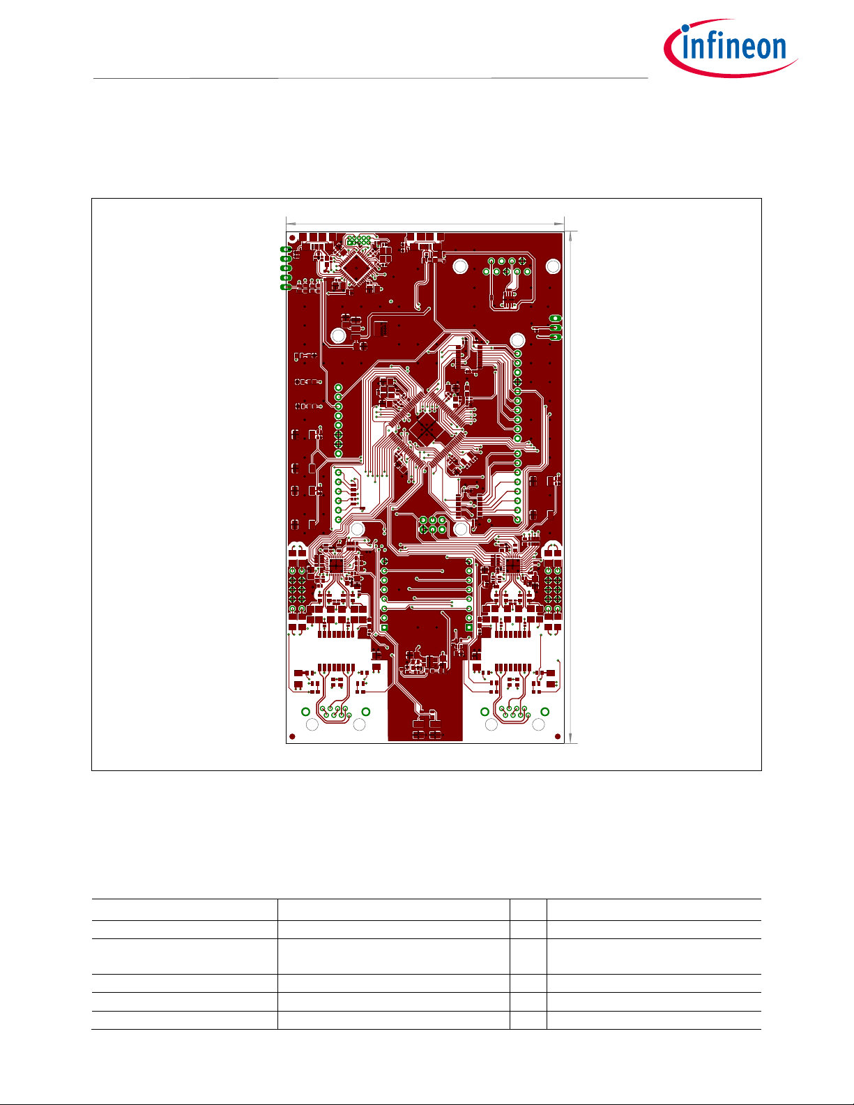
3.2 Components placement and geometry
Figure 11 shows the board dimensions and the placement of components on the PCB.
Figure 11 Components placement and geometry
3.3 Bill of material
The BOM is valid for the XMC4800 IoT Amazon FreeRTOS Connectivity kit with EtherCAT® in hardware version 1.0.
Table 7 List of material
Value
Device
Qty
Reference
d
esignator
IFX1051LE TSON8
CAN
t
ransceiver Infineon
1
IC402
15pF 50V 10% 0402 Capacitor COG 6
C116, C117, C121, C122, C400,
C401
1000pF 2kV 10% 1206
Capacitor X5R
4
C42, C56, C163, C164
10nF 50V 10% 0402
Capacitor X5R
1
C120, C201
4.7uF 10V 10% 0805
Capacitor X5R
1
C125
137.84
74.93
ADJ_3ADJ_3 ADJ_4ADJ_4
ADJ_5ADJ_5
C36C36 C37C37
C38C38
C39C39
C40C40 C41C41
C42C42
C43C43
C44C44
C45C45
C46C46
C47C47
C48C48
C49C49
C50C50
C51C51
C52C52
C53C53
C54C54
C55C55
C56C56
C60C60 C61C61
C100C100
C101
C101
C102C102 C103C103
C104
C104
C105
C105
C106
C106
C107
C107
C108C108
C109
C109
C110
C110
C111
C111
C112
C112
C113C113
C114C114
C115C115
C116C116
C117C117
C118C118
C119C119
C120C120
C121C121
C122C122
C123C123
C124C124
C125C125
C126
C126
C127C127
C128
C128
C129C129
C130
C130
C131C131
C132C132
C133C133
C150C150
C151C151 C152C152
C153C153
C154C154
C155C155
C156C156
C157C157
C158C158
C159C159
C160C160
C161C161
C162C162
C163C163
C164C164
C200C200
C201C201
C202C202
C230C230
C300C300 C301C301
C302C302C303C303
C304C304
C400
C400
C401
C401
D100D100
D101D101
D102D102 D103D103
IC100IC100
IC101
IC101
IC102IC102
IC300IC300 IC301IC301
IC402IC402
JP300JP300
L7L7
L100L100
L101L101
L102L102
L103L103
L150L150
L151L151
L251L251
LED100LED100 LED101LED101
LED102LED102
LED103LED103
LED104LED104
Q100Q100
Q101Q101
Q400
Q400
R1
R2R2
R3R3
R4
R5R5
R6R6
R7R7
R9R9
R10R10
R11R11
R18R18
R19R19
R20R20
R21R21
R22R22
R23R23
R24R24
R25R25
R26R26
R27R27
R28R28
R29R29
R30R30
R31R31
R32R32
R33R33
R34R34
R35R35
R100R100
R101R101
R102R102
R103R103
R104R104
R105R105
R106R106
R107R107
R108R108
R109R109
R110R110
R111
R111
R112R112
R113R113
R114R114
R115R115
R116R116
R118
R118
R119R119
R120R120
R121R121
R122R122
R123R123
R124R124
R125R125
R126R126
R127R127
R130R130
R150R150
R151R151
R152R152
R153R153
R154R154
R155R155
R156R156
R157R157
R158R158
R159R159
R160R160 R161R161
R162R162
R163R163
R200R200
R201R201 R202R202
R220R220
R221R221
R230R230
R231R231
R232R232
R233R233
R300R300R301R301
R302R302
R303R303
RA100RA100
RA101RA101
RA150RA150
RA151RA151
SW100SW100
SW101SW101
SW102SW102
T200T200
U150U150
U151U151
U200U200
U230U230
U250U250
U251U251
V100V100
V101V101 V150V150V151V151
V200V200
V230V230
V231V231
X100X100
X101X101
X102X102
X103X103
X150X150
X151X151
X250X250
X251X251
X400X400

User Manual 17 R1.0
2016
-
04
-
15
Production data
XMC4800 IoT Amazon FreeRTOS Connectivity kit WiFi with EtherCAT® Kit
For XMC4000 family
Value
Device
Qty
Reference
d
esignator
100 nF 50 V 10% 0402 Capacitor X7R 47
C43, C44, C4
5, C46, C47, C48, C50,
C51, C53, C54, C55, C100, C105,
C106, C107, C108, C109, C110,
C111, C112, C114, C115, C118,
C119, C123, C124, C128, C129,
C130, C131, C150, C151, C152,
C153, C154, C156, C157, C159,
C160, C161, C162, C230, C300,
C301, C302, C303, C304
100 nF 50 V 10% 1206 Capacitor X7R 8
C36, C37, C38, C39, C40, C41, C60,
C61
10 uF 10 V 10% 0805 Capacitor X7R 15
C49, C52, C101, C102, C103, C104,
C113, C126, C127, C132, C133,
C155, C158, C200, C202
ARDUINO_UNO_V2
Connection Headers for Arduino UNO
1
PCB1
MIKROE_BUS_CONN
Connection Headers for mikroBus
1
MIKROBUS1
DSUB9
-
male
Connector D
-
SUB male 9pol R/A THT
1
X400
ZX62
-
AB
-
5PA
Connector Micro USB AB SMD Hirose
2
X100, X101
43860
-
0010
Connector RJ45 R/A Molex
2
X150, X250
12 MHz 3.2x2.5
Crystal
12
MHz 4Pad NX3225SA 12
MHz NDK 2 Q100, Q101
32.768KHz 3.2x1.5
Crystal 32.768
KHz SMD 12.5pF NDK
NX3215SA-32.768K 1 Q400
ESD8V0L2B
-
03L TSLP
-
3
-
1
Diode
p
rotection Infineon
2
D100, D102
BAS3010A
-
03W SOD323
Diode Schottky 30
V 1
A Infineon
2
D101, D103
BC
M5241XA1KMLG MLP
-
32
Ethernet PHY Broadcom
2
U151, U251
PT61017PEL
Ethernet Transformer 1:1 SMD
Bourns 2 L151, L251
BLM18PG600SN1D 0603
Ferrite Bead 60R 500
mA Murata
6
L7, L100, L101, L102, L103, L150
NC7SZ157P6X
IC 2
-
Input Multiplexer
2
U150, U250
N
C7SZ125
IC Buffer with 3
-
state output
1
U230
TXS0108EPW TSSOP
-
20
IC Level Shifter 8
-
bit
2
IC300, IC301
LED GN 0603 LED green SMD 6
LED102, LED103, LED104, V101,
V151, V200
LED GE 0603
LED yellow SMD
2
V100, V150
LED GN P
-
LCC2
LED green SMD
1
V230
LED
RT 0603
LED red SMD
2
LED100, LED101
LED RT P
-
LCC2
LED red SMD
1
V231
XMC4200
-
Q48K256 QFN48
Microcontroller XMC4200 Infineon
1
IC101
XMC4800
-
F100K2048 AA
LQFP100 Microcontroller XMC4800 Infineon 1 IC100
no ass. 2x5
-
pin 0.1" female
Pin Header THT no ass
embly
1
X151
no ass. 2x5
-
pin 0.1" male
Pin Header THT no assembly
1
X251
3
-
pin 0.1"
Pin Header THT
1
JP300
no ass. 2x5pin 0.05"
Pin Header THT FTSH
-
105
-
01
-
F
-
D
-
K
no assembly 1 X10²
no ass. 5
-
pin 0.1"
Pin Header THT no assembly
1
X103
FSM2JSMA
Pushbut
ton ON SMD Tyco
3
SW100, SW101, SW102
0R 0402
Resistor
1
R110

User Manual 18 R1.0
2016
-
04
-
15
Production data
XMC4800 IoT Amazon FreeRTOS Connectivity kit WiFi with EtherCAT® Kit
For XMC4000 family
Value
Device
Qty
Reference
d
esignator
0R 1206 Resistor 8
R7, R9, R10, R11, R32, R33, R34,
R35
100R 1% 0402 Resistor 6
R100, R101, R102, R103, R104,
R105
10k 1% 0402 Resistor 7
R114, R115, R116, R119, R127,
R300, R302
10k 1% 06
03
Resistor
3
R201, R230, R231
120R 1% 0402
Resistor
1
R6
1M 10% 0402
Resistor
2
R106, R125
1k24 1% 0603
Resistor
2
R26, R153
1k5 1% 0603
Resistor
2
R202, R233
22R 1% 0402
Resistor
2
R107, R108, R120, R121
270R 1% 0603
Resistor
4
R29, R30, R158, R159
2k2 1% 0603
Resistor
2
R31, R152
49R9 1% 0603 Resistor 12
R22, R23, R24, R25, R27, R28,
R150, R151, R154, R155, R156,
R157
4k7 1% 0402
Resistor
1
R126
4k7 1% 0603
Resistor
1
R232
4k87 1% 0603
Resistor
1
R200
510R 1% 0402
Resistor
3
R111, R118, R122
680R 1% 0603 Resistor 7
R112, R113, R123, R124, R130,
R220, R221
75R 1/ 0603 Resistor 8
R18, R19, R20, R21, R160, R161,
R162, R163
no ass. 0R 0402
Resistor
1
R3
no ass. 0R 0402
Resistor
1
R303
no ass. 0R 0402
Resistor
2
R109, R301
no ass. 0R 1206
Re
sistor
4
R1, R2, R4, R5
4*49R9 1% ARRAY4_0.8
Resistor Array
4
RA100, RA101, RA150, RA151
BCR108W SOT323
Transistor NPN Infineon
1
T200
IFX1117MEV33 SOT223
Voltage
r
egulator 3.3
V Infineon
1
IC102
IFX54441LDV TSON
-
10
Voltage
r
egulator adj. Infineon
1
U200

User Manual 19 R1.0
2016
-
04
-
15
Production data
XMC4800 IoT Amazon FreeRTOS Connectivity kit WiFi with EtherCAT® Kit
For XMC4000 family
Revision history
Major changes since the last revision
Page or r
eference
Description of change

Trademarks of Infineon Technologies AG
µHVIC™, µIPM™, µP
FC™, AU
-
ConvertIR™, AURIX™, C166™, CanPAK™, CIPOS™, CIPURSE™, CoolDP™, CoolGaN™, COOLiR™, CoolMOS™, CoolSET™,
CoolSiC™, DAVE™, DI-
POL™, DirectFET™, DrBlade™, EasyPIM™, EconoBRIDGE™, EconoDUAL™, EconoPACK™, EconoPIM™, EiceDRIVER™, eupec™,
FCOS™, GaNpowIR™, HEXFET™, HITFET™, HybridPACK™, iMOTION™, IRAM™, ISOFACE™, IsoPACK™, LEDrivIR™, LITIX™, MIPAQ™, ModSTACK™, my
-
d™, NovalithIC™, OPTIGA™, OptiMOS™, ORIGA™, PowIRaudio™, PowIRStage™, PrimePACK™, PrimeSTACK™, PROFET™, PRO-
SIL™, RASIC™, REAL3™,
SmartLEWIS™, SOLID FLASH™, SPOC™, StrongIRFET™, SupIRBuck™, TEMPFET™, TRENCHSTOP™, TriCore™, UHVIC™, XHP™, XMC™
Trademarks updated November 2015
Other Trademarks
All referenced product or service names and trademarks are the property of their respective
owners.
EtherCAT®
is registered trademark and patented technology, licensed by Beckhoff Automation GmbH, Germany.
Edition
2016
-
04
-
15
UG_201604_PL30_017
Published by
Infineon Technologies AG
81726 Munich, Germany
© 2019 Infineon Technologies AG.
All Rights Reserved.
Do you have a question about this
document?
Email: erratum@infineon.com
Document reference
IMPORTANT NOTICE
The information contained in this application note
is given as a hint for the implementation of the
product only and shall in no event be regarded as
a description or warranty of a certain
functionality, condition or quality of the product.
Before implementation of the product, the
recipient of this application note must verify any
function and other technical information given
herein in the real application. Infineon
Technologies hereby disclaims any and all
warranties and liabilities of any kind (including
without limitation warranties of non-infringement
of intellectual property rights of any third party)
with respect to any and all information given in
this application note.
The data contained in this document is exclusively
intended for technically trained staff. It is the
responsibility of customer’s technical departments
to evaluate the suitability of the product for the
intended application and the completeness of the
product information given in this document with
respect to such application.
For further information on
the product,
technology, delivery terms and conditions and
prices please contact your nearest Infineon
Technologies office (www.infineon.com).
WARNINGS
Due to technical requirements products may
contain dangerous substances. For information on
the types in question please contact your nearest
Infineon Technologies office.
Except as otherwise explicitly approved by
Infineon Technologies in a written document
signed by authorized representatives of Infineon
Technologies, Infineon Technologies’ products
may not be used in any applications where a
failure of the product or any consequences of the
use thereof can reasonably be expected to result in
personal injury.
Other manuals for XMC4800
2
Table of contents
Other Infineon Recording Equipment manuals


 installation manual")


