Infineon uIO-Stick v2 User manual

uIO-Stick v2
User guide
Z8F80464029
About this document
Scope and purpose
This user guide intends to help getting started with the uIO-Stick v2. The uIO-Stick v2 acts as an interface stick
between the PC and EvalBoards of the MOTIX™MCU devices.
This user guide provides additional information about the layout, interfaces and the pinout of the uIO-Stick v2.
Intended audience
This document is for everyone who works with the uIO-Stick v2.
User guide Please read the sections "Important notice" and "Warnings" at the end of this document Rev. 1.00
www.infineon.com 2023-05-30

Important notice
“Evaluation Boards and Reference Boards” shall mean products embedded on a printed circuit board
(PCB) for demonstration and/or evaluation purposes, which include, without limitation, demonstration,
reference and evaluation boards, kits and design (collectively referred to as “Reference Board”).
Environmental conditions have been considered in the design of the Evaluation Boards and Reference
Boards provided by Infineon Technologies. The design of the Evaluation Boards and Reference Boards has
been tested by Infineon Technologies only as described in this document. The design is not qualified in
terms of safety requirements, manufacturing and operation over the entire operating temperature range
or lifetime.
The Evaluation Boards and Reference Boards provided by Infineon Technologies are subject to functional
testing only under typical load conditions. Evaluation Boards and Reference Boards are not subject to
the same procedures as regular products regarding returned material analysis (RMA), process change
notification (PCN) and product discontinuation (PD).
Evaluation Boards and Reference Boards are not commercialized products, and are solely intended for
evaluation and testing purposes. In particular, they shall not be used for reliability testing or production.
The Evaluation Boards and Reference Boards may therefore not comply with CE or similar standards
(including but not limited to the EMC Directive 2004/EC/108 and the EMC Act) and may not fulfill other
requirements of the country in which they are operated by the customer. The customer shall ensure that
all Evaluation Boards and Reference Boards will be handled in a way which is compliant with the relevant
requirements and standards of the country in which they are operated.
The Evaluation Boards and Reference Boards as well as the information provided in this document
are addressed only to qualified and skilled technical sta, for laboratory usage, and shall be used
and managed according to the terms and conditions set forth in this document and in other related
documentation supplied with the respective Evaluation Board or Reference Board.
It is the responsibility of the customer’s technical departments to evaluate the suitability of the
Evaluation Boards and Reference Boards for the intended application, and to evaluate the completeness
and correctness of the information provided in this document with respect to such application.
The customer is obliged to ensure that the use of the Evaluation Boards and Reference Boards does not
cause any harm to persons or third party property.
The Evaluation Boards and Reference Boards and any information in this document is provided "as is"
and Infineon Technologies disclaims any warranties, express or implied, including but not limited to
warranties of non-infringement of third party rights and implied warranties of fitness for any purpose, or
for merchantability.
Infineon Technologies shall not be responsible for any damages resulting from the use of the Evaluation
Boards and Reference Boards and/or from any information provided in this document. The customer is
obliged to defend, indemnify and hold Infineon Technologies harmless from and against any claims or
damages arising out of or resulting from any use thereof.
Infineon Technologies reserves the right to modify this document and/or any information provided
herein at any time without further notice.
uIO-Stick v2
User guide
Important notice
User guide 2 Rev. 1.00
2023-05-30
Safety precautions
Note: Please note the following warnings regarding the hazards associated with development systems.
Table 1 Safety precautions
Caution: The heat sink and device surfaces of the evaluation or reference board
may become hot during testing. Hence, necessary precautions are required while
handling the board. Failure to comply may cause injury.
Caution: Only personnel familiar with the drive, power electronics and associated
machinery should plan, install, commission and subsequently service the system.
Failure to comply may result in personal injury and/or equipment damage.
Caution: The evaluation or reference board contains parts and assemblies
sensitive to electrostatic discharge (ESD). Electrostatic control precautions are
required when installing, testing, servicing or repairing the assembly. Component
damage may result if ESD control procedures are not followed. If you are
not familiar with electrostatic control procedures, refer to the applicable ESD
protection handbooks and guidelines.
Caution: A drive that is incorrectly applied or installed can lead to component
damage or reduction in product lifetime. Wiring or application errors such as
under-sizing the motor, supplying an incorrect or inadequate DC supply, or
excessive ambient temperatures may result in system malfunction.
Caution: The evaluation or reference board is shipped with packing materials
that need to be removed prior to installation. Failure to remove all packing
materials that are unnecessary for system installation may result in overheating or
abnormal operating conditions.
uIO-Stick v2
User guide
Safety precautions
User guide 3 Rev. 1.00
2023-05-30

Table of contents
About this document . . . . . . . . . . . . . . . . . . . . . . . . . . . . . . . . . . . . . . . . . . . . . . . . . . . . . . . . . . . . . . . . . . . 1
Important notice . . . . . . . . . . . . . . . . . . . . . . . . . . . . . . . . . . . . . . . . . . . . . . . . . . . . . . . . . . . . . . . . . . . . . . . 2
Safety precautions . . . . . . . . . . . . . . . . . . . . . . . . . . . . . . . . . . . . . . . . . . . . . . . . . . . . . . . . . . . . . . . . . . . . . 3
Table of contents . . . . . . . . . . . . . . . . . . . . . . . . . . . . . . . . . . . . . . . . . . . . . . . . . . . . . . . . . . . . . . . . . . . . . . . 4
1 Overview . . . . . . . . . . . . . . . . . . . . . . . . . . . . . . . . . . . . . . . . . . . . . . . . . . . . . . . . . . . . . . . . . . . . . . . . . . . . . . 5
1.1 Description . . . . . . . . . . . . . . . . . . . . . . . . . . . . . . . . . . . . . . . . . . . . . . . . . . . . . . . . . . . . . . . . . . . . . . . . . . . . . 5
1.2 Block diagram . . . . . . . . . . . . . . . . . . . . . . . . . . . . . . . . . . . . . . . . . . . . . . . . . . . . . . . . . . . . . . . . . . . . . . . . . . 5
2 Hardware connection . . . . . . . . . . . . . . . . . . . . . . . . . . . . . . . . . . . . . . . . . . . . . . . . . . . . . . . . . . . . . . . . . . 7
3 Comparison of uIO-Stick and uIO-Stick v2 . . . . . . . . . . . . . . . . . . . . . . . . . . . . . . . . . . . . . . . . . . . . . . . 8
4Soware . . . . . . . . . . . . . . . . . . . . . . . . . . . . . . . . . . . . . . . . . . . . . . . . . . . . . . . . . . . . . . . . . . . . . . . . . . . . . . .9
5 Acronyms . . . . . . . . . . . . . . . . . . . . . . . . . . . . . . . . . . . . . . . . . . . . . . . . . . . . . . . . . . . . . . . . . . . . . . . . . . . . .10
Revision history . . . . . . . . . . . . . . . . . . . . . . . . . . . . . . . . . . . . . . . . . . . . . . . . . . . . . . . . . . . . . . . . . . . . . . .11
Disclaimer . . . . . . . . . . . . . . . . . . . . . . . . . . . . . . . . . . . . . . . . . . . . . . . . . . . . . . . . . . . . . . . . . . . . . . . . . . . . 12
uIO-Stick v2
User guide
Table of contents
User guide 4 Rev. 1.00
2023-05-30
1 Overview
1.1 Description
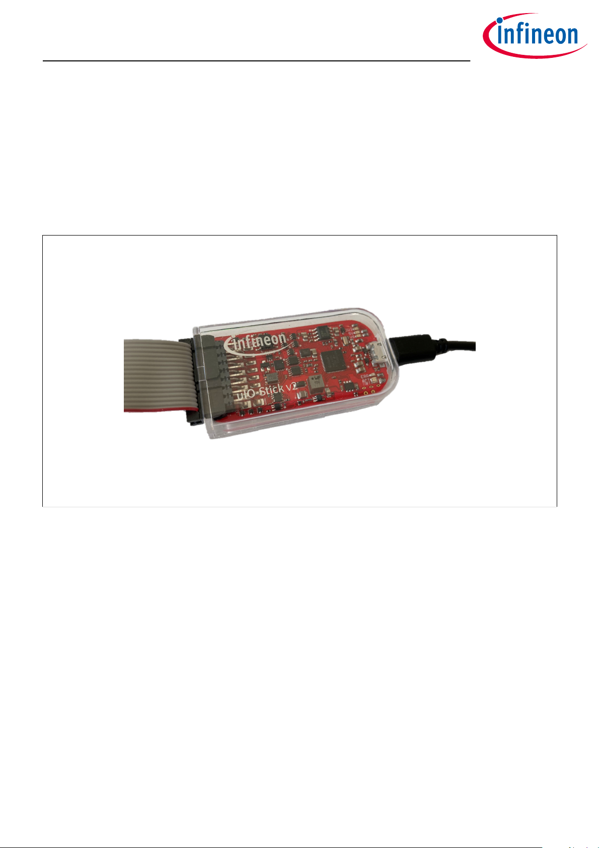
The uIO-Stick v2 is an interface device for controlling EvalBoards of the MOTIX™MCU devices during run time
through PC.
It oers a USB connection to the PC, and several dierent functionalities, for example SPI, CAN, and GPIOs.
The uIO-Stick v2 registers as an HID on the PC, so no driver installation is needed.
Figure 1 uIO-Stick v2
1.2 Block diagram
The uIO-Stick v2 contains an XMC4200 microcontroller which provides the necessary hardware interface and
handles the protocols. LIN and CAN are implemented as true physical layers (using transceivers), while the
digital lines (SPI, GPIOs) provide a 3.3 V or 5 V digital level (configurable by SW). In addition, a boost converter is
implemented to generate a 12 V supply for the target device and the integrated LIN transceiver.
uIO-Stick v2
User guide
1 Overview
User guide 5 Rev. 1.00
2023-05-30

Figure 2 uIO-Stick v2 block diagram
uIO-Stick v2
User guide
1 Overview
User guide 6 Rev. 1.00
2023-05-30
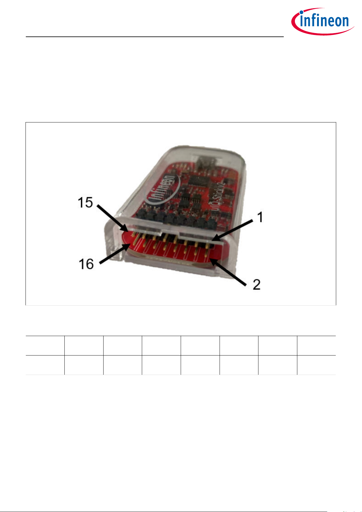
2 Hardware connection
The uIO-Stick v2 can be connected to the user PC via USB. For this purpose, it has a micro-USB socket. A
micro-USB cable is not included in the packaging.
For connection to an embedded device, the uIO-Stick oers several dierent interfaces available on a 16-pin
header. The connector cable, included in the packaging, fits to the 16-pin connector on the EvalBoards of the
MOTIX™MCU devices. The following figure and table describe the pinout of the 16-pin connector.
Figure 3 uIO-Stick v2 pinout - image
Table 2 Pinout of uIO-Stick v2
Pin 15: SPI
MOSI
Pin 13: SPI
MISO
Pin 11: SPI
CLK
Pin 9: SPI CS Pin 7: Reset Pin 5: LIN Pin 3: CANL,
RXD
Pin 1: CANH,
TXD
Pin 16:
Analog In
Pin 14:
GPIO0
Pin 12:
GPIO1
Pin 10:
GPIO2
Pin 8: GPIO3 Pin 6: VS Pin 4: 5V Pin 2: GND
Additional remarks:
• Pin 2 - GND: the common ground connection to the target system
• Pin 5 - LIN: can be directly connected to a LIN network; is the LIN bus connection to the LIN transceiver
implemented in the uIO-Stick v2
• Pin 6 - VS: can either be driven from the implemented boost converter on the uIO-Stick v2 (+12 V) or can
be overridden by an external supply, for example the supply of the target device. This pin is also used to
internally drive the LIN transceiver available on the uIO-Stick v2
• Pin 7 - Target Reset: intended to drive the reset input of the target device
uIO-Stick v2
User guide
2 Hardware connection
User guide 7 Rev. 1.00
2023-05-30

3 Comparison of uIO-Stick and uIO-Stick v2
The following table gives a comparison between uIO-Stick and uIO-Stick v2.
Table 3
Feature uIO-Stick uIO-Stick v2
Connection to PC USB-A plug Micro-USB socket
Connection to target device 16-pin socket 16-pin socket
Interface UART Not available Available
Interface RS232 Available Not available
Interface CAN Not available Available
Interface LIN Available Available
Interface Reset line Available Available
Interface SPI Available Available
Interface GND Available Available
Interface 5 V Available Available
Interface 12 V Available Available
Interface 4 GPIOs Available Available
Interface Analog Input Available Available
Logical level 3.3 V and 5 V (SW
selectable)
Available Available
uIO-Stick v2
User guide
3 Comparison of uIO-Stick and uIO-Stick v2
User guide 8 Rev. 1.00
2023-05-30


5 Acronyms
The following acronyms and terms are used within this document.
Table 4 Acronyms
Acronyms Name
CAN Controller area network
CANH Controller area network high
CANL Controller area network low
CLK Clock
CS Chip select
GND Ground
GPIO General-purpose input/output
HID Human interface device
LIN Local interconnect network
MISO Master in, slave out
MOSI Master out, slave in
RXD Receive data
SPI Serial peripheral interface
SW Soware
TXD Transmit data
USB Universal serial bus
UART Universal asynchronous receiver-transmitter
VS Supply voltage
uIO-Stick v2
User guide
5 Acronyms
User guide 10 Rev. 1.00
2023-05-30

Revision history
Document
version
Date of
release
Description of changes
Rev. 1.00 2023-05-30 Initial document release
uIO-Stick v2
User guide
Revision history
User guide 11 Rev. 1.00
2023-05-30

Trademarks
All referenced product or service names and trademarks are the property of their respective owners.
Edition 2023-05-30
Published by
Infineon Technologies AG
81726 Munich, Germany
©2023 Infineon Technologies AG
All Rights Reserved.
Do you have a question about any
aspect of this document?
Email: [email protected]om
Document reference
IFX-hfd1673535012883
Important notice
The information given in this document shall in no
event be regarded as a guarantee of conditions or
characteristics (“Beschaenheitsgarantie”).
With respect to any examples, hints or any typical
values stated herein and/or any information regarding
the application of the product, Infineon Technologies
hereby disclaims any and all warranties and liabilities
of any kind, including without limitation warranties of
non-infringement of intellectual property rights of any
third party.
In addition, any information given in this document is
subject to customer’s compliance with its obligations
stated in this document and any applicable legal
requirements, norms and standards concerning
customer’s products and any use of the product of
Infineon Technologies in customer’s applications.
The data contained in this document is exclusively
intended for technically trained sta. It is the
responsibility of customer’s technical departments to
evaluate the suitability of the product for the intended
application and the completeness of the product
information given in this document with respect to such
application.
Warnings
Due to technical requirements products may contain
dangerous substances. For information on the types
in question please contact your nearest Infineon
Technologies oice.
Except as otherwise explicitly approved by Infineon
Technologies in a written document signed by
authorized representatives of Infineon Technologies,
Infineon Technologies’ products may not be used in
any applications where a failure of the product or
any consequences of the use thereof can reasonably
be expected to result in personal injury.
Table of contents
Other Infineon Recording Equipment manuals


