Infinite AERINOS ADS-270 User manual
AERINOS®LoRaWAN IoT Platform
ADS-270 LoRa End Node
User Guide

ADS-270 User Guide
2
Document version: 1.1
Hardware version 1.0, Firmware version: 1.0
Copyright © 2020 –Infinite Informatics Ltd
All rights reserved.
Disclaimer
•While every effort has been made to ensure that the information in this guide is
accurate and complete, no liability can be accepted for any errors or omissions.
•Infinite Ltd reserves the right to change the specifications of the hardware and
software described in this guide at any time without prior notice.
•No part of this guide may be reproduced, transmitted, stored in fixed or removable
media or translated into any language in any form without the prior written
permission of Infinite Informatics Ltd.
•Infinite makes no warranties for damages resulting from corrupted or lost data
due to malfunction of the hardware or the software.

ADS-270 User Guide
3
Contents
1. Introduction 4
2. Operation modes 4
3. Hardware setup 5
3.1 Packing list 5
3.2 Opening the enclosure 5
3.3 Connectors & Jumper settings 6
3.4 Battery installation 7
3.5 Wiring the digital (Counter) Input 8
3.6 Wiring the analog input 9
3.7 Wiring the SDI-12 Serial Bus 11
3.8 Wiring the RS-485 Bus 11
4. Device configuration 12
4.1 Configuring DI1 as Counter input 12
4.2 Configuring AI1 as Analog Input 12
4.3 Configuring the SDI-12 channels 13
4.4 Configuring the MODBUS (RS-485) channels 15
4.5 Data Acquisition Parameters 16
4.6 Message Format 16
4.7 LORAWAN Parameters 17
5. Programming the Unit 18
6. Technical characteristics 19
7. Command Summary 20
7.1 Configuration Commands 20
7.2 Verification Commands 21
8. References 21

ADS-270 User Guide
4
1. Introduction
LoRaWAN is a communication protocol and a system architecture that is used to read
data from sensors through a dynamic network of gateways (end devices do not join a
single base station). LoRaWAN uses a chirp spread spectrum (CSS) modulation and
operates in the license free bands (ISM).
ADS-270 is an ultra low power, battery powered end node for the LoRa network. The
unit is available for the 863 to 870 MHz band. It incorporates two inputs, one digital
with pulse counter capability and one analog, as well as multiple excitation options for
powering transducers.
The device supports acquisition of up to 8 measurement channels, based on the
popular SDI-12 communication protocol and 8 channels, based on the MODBUS
protocol. ADS-270 can send an unlimited number of messages per day. The unit
incorporates a Lithium Thionyl Battery supplying system operation for up to 10 years.
ADS-270 User Guide
5
2. Operation modes
Modes of operation include:
1. Battery supplied cyclic operation.
2. External power adaptor supplied cyclic operation. The transition between the
two operation modes is uninterruptible.
3. Operation suspension for the device configuration.
3. Hardware setup
3.1 Packing list
1. ADS-270 Unit
2. Lithium Thionyl Battery (optional)
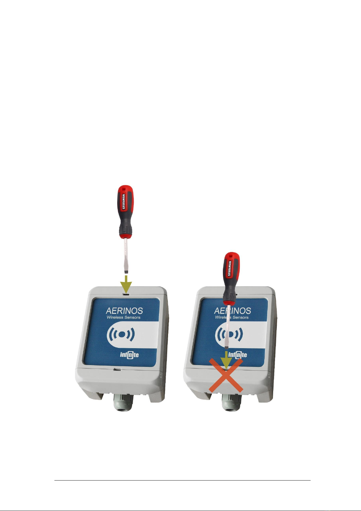
3.2 Opening the enclosure
Open the unit enclosure by inserting a screwdriver in the slot on the enclosure’s top.
Right Wrong

ADS-270 User Guide
6
3.3 Connectors & Jumper settings
3.3.1 LED
D14: Status LED, Blinking in configuration mode.
3.3.2 Connectors
JMP1: Put a Jumper to enter configuration mode.
J1: USB Serial connector. The unit can be supplied through the USB connector for
configuration and test.
Caution: Remove the external power supply (J3), if applied, before connecting the
USB connector!
J2: Battery connector.
J3: External power supply, 5V (stabilized).
J4-1: 12VDC sensor excitation (switched)
J4-2: 5VDC sensor excitation (switched)
J4-3: GND (COM), Common for AI1
J5-1: DI1, Digital Input (Counter: software selectable)
J5-2: SDI-12 data line

ADS-270 User Guide
7
J5-3: RS-485 bus (-)
J5-4: RS-485 bus (+)
J5-5: AI1, Analog Input
3.3.3 Switches
S1: Test mode button
3.4 Battery installation
WARNING: Pay attention to the correct polarity during battery
installation! The right polarity is marked up on the Battery Holder. The unit is
protected against reverse polarity.

ADS-270 User Guide
8
3.5 Wiring the digital (Counter) Input
COM: GND
Digital Input states are:
Contact closed →Input state: ON (logical ‘H’)
Contact open →Input state: OFF (logical ‘L’)
ADS-270 User Guide
9
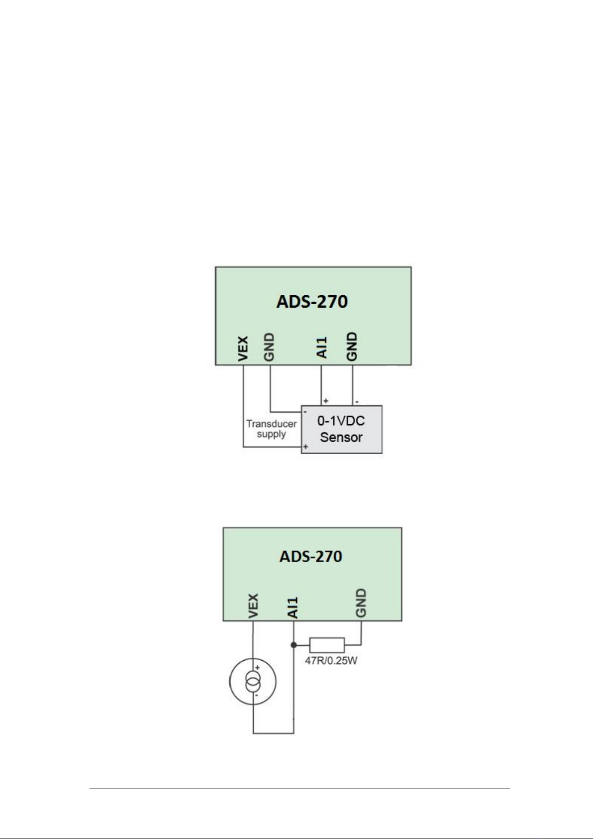
3.6 Wiring the analog input
ADS-270 incorporates 1 analog input with 12 bit resolution. The Analog input is
scanned according to the selected message transmission period (see 4.5.2).
For current measurements, an external 47R/0.25W resistor can be applied between
the input terminals (J4-3 and J5-5) on AI1.
ADU-270 incorporates two excitation outputs (12V, 5V) to supply external
transducers. The excitation output switches ON/OFF according to the selected
message transmission period (see 4.5.2).
Low power transducers are recommended for preserving longer battery lifetime.
The unit performs 100 consecutive readings of the analog input for every sample,
thereby neglecting the maximum and minimum values and calculates the average of
the remaining 98 values.
3.6.1 0-1V Transducers
Scale settings: 0..1V →Raw scale:0..4095
3.6.2 Two Wire 0-20/4-20mA transducers
Scale settings: 0..20mA, Raw scale:0..3846
ADS-270 User Guide
10
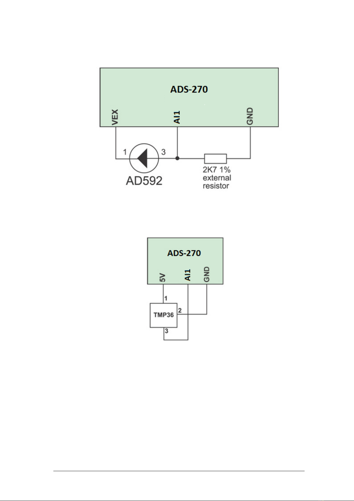
3.6.3 AD592 temperature transducer (-25°C … 105°C)
Scale settings: -25°C … 105°C
Sensor Output: 0.641V..0.977V, Raw scale: 2625..4001
3.6.4 TMP36 temperature transducer (-40°C …50°C)
Scale settings: -40°C … 50°C
Sensor Output: 0.1V..1V, Raw scale: 410..4095

ADS-270 User Guide
11
3.7 Wiring the SDI-12 Serial Bus
SDI-12 is an asynchronous, ASCII, serial communications protocol that was
developed for intelligent sensory instruments that typically monitor environmental
data. The communication is achieved by digital communications. The addressing
system allows data recorder to communicate with several microprocessor-based
sensors over a single line.
ADS-200 is compliant to the SDI-12 Standard Version 1.2 and supports extended
commands for sensor configuration, in terminal mode. ADS-200 can collect data from
several SDI-12 sensors for a total amount of 8 measurement channels.
SDI-12 connections:
J5-2: SDI data line
J4-3: GND
J4-1: 12V excitation output. The 5V excitation output (J4-2) can be used instead, for
sensors with a 5VDC supply option.
It is recommended to read the sensor manufacturers’ Sensor Manual and the SDI-12
Specification by the SDI-12 Support Group[1] before utilizing the corresponding
functions of the ADS-270 device.
3.8 Wiring the RS-485 Bus
ADU-500 supports the popular MODBUS protocol over a differential RS-485 bus. The
bus line is internally terminated with a 120Ωresistor.

ADS-270 User Guide
12
4. Device configuration
4.1 Configuring DI1 as Counter input
The command enables counting mode on DI1. The Counter (0-65535) is cleared
according to a Clear Mode parameter, thereby acting as a Totalizer.
1150,n
1150: Command ID
n: 1, CNT number
4.1.1 Counter Scale factor
1154,n,f
1154: Command ID
n: 1, CNT number
f: 0.000-0.999, Counter Scale factor
4.1.2 Set Counter Clear Mode
1158,n,c
1158: Command ID
n: 1, CNT number
m: 0-1, 0→No Clear (Totalizer), 1→Clear on Sampling
4.1.3 Counter Preset
1181,n,v
1154: Command ID
n: 1, CNT number
f: Preset value
4.1.4 Reset Counter
Resets the counter value to 0.
1180,n
1154: Command ID
n: 1, CNT number
4.1.5 Clear Counter Configuration
1160,n
1160: Command ID
n: 1, CNT number

ADS-270 User Guide
13
4.2 Configuring the Analog Input
The AI configuration command structure is:
1200,n,ssl,ssh,sl,sh
1200: Command ID
n: 1, AI number
ssl: Sensor scale low (Row value 0-4095)
ssh: Sensor scale high (Row value 0-4095)
sl: User scale low
sh: User scale high
4.2.1 Clear AI Configuration
1210,n
1210: Command ID
n: 1, AI number
4.3 Configuring the SDI-12 channels
ADS-270 supports up to 8 channels.
The configuration command for a SDI-12 channel is:
1230,n,a,m,i
1230: Command ID
n: Channel number (1-8)
a: Sensor address
m: Measurement set (0 for the aM! command, 1-9 for the aM1!–aM9! commands)
i: Parameter
ADS-270 addresses the SDI-12 sensors using the basic measurement starting
commands aM! (aMx!) and the D0!...D9! send data commands.
4.3.1 SDI-12 acquisition scheme
ADS-270 sends a start measurement command to the SDI-12 serial bus:
aMm!
where,
a: sensor address
M: Start measurement command
m: void or 1-9, Measurement set (aM! or aM1! to aM9!)
This command tells the sensor with address ‘a’ to take a measurement.
The sensor responds with:
atttn
where,
a: sensor address
ttt: the specified time, in seconds, until the sensor will have the measurement(s)
ready
n - the number of measurement values the sensor will make and return in one or
more subsequent D commands; n is a single digit integer with a range of 0 to 9
ADS-270 waits for either of two events to occur before issuing a D0 command:
1) receipt of a service request (a<CR><LF>) from the sensor
2) the specified time to elapse (ttt seconds)
ADS-270 issues one or more read commands (aD0! to aD9!) to read the
measurement parameters. Each parameter corresponds to one channel according to
the channel configurations:

ADS-270 User Guide
14
aD0! (aD1!...aD9!)
The addressed sensor responds with:
a<values><CR><LF>
where,
<values> - pd.d
p - the polarity sign (+ or -)
d - numeric digits before the decimal place . - the decimal point (optional)
d - numeric digits after the decimal point. the maximum number of digits for a data
value is 7, even without a decimal point, the minimum number of digits for a data
value (excluding the decimal point) is 1, the maximum number of characters in a
data value is 9 (the (polarity sign + 7 digits + the decimal point))
Example:
A soil measurement sensor returns three parameters:
1. Soil moisture in Water fraction by Volume (wfv)
2. Soil Conductivity in Siemens/Meter (S/m)
3. Temperature in °C
Two sensors (addresses 1 and 2) are connected to the SDI-12 serial bus.
The configuration commands are:
1230,1,1,0,1
1230,2,1,0,2
1230,3,1,0,3
1230,4,1,0,1
1230,5,1,0,2
1230,6,1,0,3
4.3.2 Clear SDI-12 channel configuration
The command clears the specified SDI-12 channel configuration.
1238,n
1238: Command ID
n: 1-8, SDI-12 number
4.3.3 Clear all SDI-12 channels
The command clears all declared SDI-12 channels.
1239
1239: Command ID

ADS-270 User Guide
15
4.4 Configuring the MODBUS (RS-485) channels
ADU-500 supports up to 8 MODBUS channels.
The configuration command for a MODBUS channel is:
1241,n,a,c,sr,nr
1241: Command ID
n: Channel number (1-8)
a: RS-485 address
m: MODBUS command
sr: Start register
nr: Number of registers
4.4.1 Start Measurement Trigger command
The command concerns sensors requiring a trigger to make a measurement.
1240,a,r,v
1240: Command ID
a: RS-485 address
r: Register
v: Value
4.4.2 Clear MODBUS channel configuration
The command clears a MODBUS channel configuration.
1248,n
1248: Command ID
n: Channel number
4.4.3 Clear all MODBUS channels
The command clears a MODBUS channel configuration.
1249
1249: Command ID
4.4.4 Set MODBUS baud rate
The command sets the baud rate for the MODBUS communications. The other
settings are fixed: Data bits: 8, Parity: none, Stop bits: 1
1245,b
1245: Command ID
b: Baud rate: 9600, 19200, 38400, 57600, 115200
4.4.5 Set MODBUS protocol
The command sets the protocol for the MODBUS communications.
1244,p
1244: Command ID
p: Protocol: 0: RTU, 1: ASCII

ADS-270 User Guide
16
4.5 Data Acquisition Parameters
4.5.1 Sampling delay (Warm up time)
The parameter defines an idle period between switching on the excitation and reading
the measurements from the analog and the SDI-12 channels. This option should be
set according to the transducer with the longest warm up time for stable reading. The
value of this parameter affects strongly the battery life.
1291,d
d: 0-255 sec
4.5.2 Message transmission period
The parameter defines the message transmission period to the LoRaWAN network.
The period should be set according to the number of channels selected for
acquisition. Every message contains one channel. The minimum value is 1 minute.
The value of this parameter affects strongly the battery life.
1292,p
p: 1-255 min
4.6 Message Format
The message is in ASCII format and has a fixed length of 12 byte.
L1
L0
D9
D8
D7
D6
D5
D4
D3
D2
D1
IN
L0, L1: 0-F, HEX, Channel Number
D1-D9: Measurement value
D9: +/-, Sign
D1-D8: Value, can contain a decimal point
IN: 0-1, Digital Input value
Channel numbers:
01: Analog input value, AI1
15 , 16, 17, 18, 19, 1A, 1B, 1C: SDI-12 Channels 1-8
5B: Counter value
AB, AC, AD, AE, AF, B0, B1, B2: MODBUS Channels 1-8
IN: Digital Input value: 1: ON, 0: OFF
Examples:
AI1 has the value of -16.7, Digital input is ON.
The Message contents is: 01-000016.71
SDI-12 Channel 7 has the value of 23.3440, Digital input is ON.
The Message contents is: 1B+023.34401
MODBUS Channel 2 has the value of 48546, Digital input is OFF.
The Message contents is: AC+000485460

ADS-270 User Guide
17
4.7 LORAWAN Parameters
4.7.1 Device Address
The command sets the unique device address.
9410,s
s: 00000000-FFFFFFFF, 4-byte hexadecimal number representing the device
address, from
4.7.2 Device EUI
The command sets the globally unique device address.
9420,s
s: 8-byte hexadecimal number representing globally unique device identifier (EUI).
The parameter is internally set. It is recommended not to change this value.
4.7.3 Set Application EUI
The command sets the Application identifier.
9430,s
s: 8-byte hexadecimal number representing the Application EUI.
4.7.4 Set the Network Session Key
The command sets the Network Session Key.
9440,s
s: 16-byte hexadecimal number representing the network session key.
4.7.5 Set the Network Application Key
The command sets the Network Session Key.
9450,s
s: 16-byte hexadecimal number representing the network application key.
4.7.6 Set LoRa Data Rate
The command sets the LoRa Data Rate.
9460,n
n: 0-7, decimal number representing the data rate.
4.7.7 Set uplink frame counter
The command presets the uplink frame counter.
9470,c
c: 0 - 4294967295, decimal number representing the value of the uplink frame
counter that will be used for the next uplink transmission.
4.7.8 Set Power Index
The command sets the LoRa Power Index.
9480,p
p: 1-5, decimal number representing the power index.

ADS-270 User Guide
18
5. Programming the unit
The way to enter the unit setup mode is the following:
1. Install the USB driver on a PC.
2. Connect the USB port to a PC. The Status LED is lighting for 2 sec.
3. Put a Jumper on JMP1. The Status LED starts blinking, indicating setup mode.
Program execution is suspended.
There are two ways to program the unit:
1. Connecting the unit to a PC and using a terminal program to pass the ASCII
commands to the unit, according to the scheme: “Command, Parameters <CR>”.
The terminal settings should be: Baud rate: 115200 bps, Data bits: 8, Parity:
none, Stop bits: 1, Flow control: none.
2. Connecting the unit to a PC and using the WA Manager software. This is the
most convenient way. The Device EUI, which is necessary for connecting the
unit to the LoRaWAN network, is automatically read during downloading the
parameter file to the device. The Device EUI is also printed on a label in the
device interior.

ADS-270 User Guide
19
6. Technical characteristics
Power supply
Internal 3.6V Ah Lithium Thionyl battery
External 5VDC stabilized power adaptor
USB interface (Configuration)
Temperature
Operation
Storage
-40 to 65 ºC
-45 to 85 ºC
Current draw
Standby
Measurement
Messaging
18 uA max
6.5 mA (w/o sensor current)
44.5 mA
Radio characteristics
863-870 MHz Band
Uplink data rate (TX): up to 300Kbps with FSK modulation
Max output power: +14dBm
Digital inputs
1, 0-30VDC or potential free contacts
Pulse counters
1, 2KHz, DI1
Analog inputs
1, 12bit resolution, AI1
SDI-12 Bus
8 Channels, multiple sensor support
RS-485
8 Channels, multiple sensor support
Excitation
12VDC/250mA, 5VDC/200mA
Serial port
USB 2, 9600 to 115200bps
Indications
1 LED, Device status
Protection
IP66
Dimensions
130 x 130 x 75 mm
Weight
0.5 kg

ADS-270 User Guide
20
7. Command Summary
7.1 Configuration Commands
Cmd
Description
Syntax
Comments
0160
Clear Event Log
cmd
0183
Set Factory Defaults
cmd,cmd
0205
Reset Unit Operation
cmd,cmd
0301
Set Device ID
cmd,id,p
id: unit ID, p: password
0790
Show Status Messages
cmd
0791
Hide Status Messages
cmd
1150
Enable Counter
cmd,n
n: counter
1154
Set Counter Scale Factor
cmd,n,f
n: counter, f: factor
1158
Set Counter Auto Clear
cmd,n,c
n: counter, c: auto clear
(0: no, 1: yes)
1160
Clear Counter Configuration
cmd,n
n: counter
1180
Clear Counter
cmd,n
n: counter
1181
Preset Counter
cmd,n,v
n: counter, v: value
1200
Set AI Configuration
cmd,n,ssl,ssh,sl,sh
ssl/ssh: sensor scale l/h,
sl/sh: User scale l/h
1210
Clear AI Configuration
cmd,n
n: AI
1230
Set SDI-12 Channel Configuration
cmd,n,a,m,i
n: SDI AI, a: sensor address,
m: parameter set, i:
parameter index
1238
Clear SDI-12 Channel Configuration
cmd,n
n: SDI AI
1239
Clear All SDI-12 Channel Configuration
cmd
1240
Set Modbus Trigger Command
cmd,a,r,v
a: address, r: reg, v: value
1241
Set Modbus Channel Configuration
cmd,n,a,c,sr,nr
n: Modbus AI, a: address, c:
command, sr: start reg, nr:
number of regs
1248
Clear Modbus Channel Configuration
cmd,n
n: Modbus AI
1249
Clear All Modbus Channels Configuration
cmd
1250
Set Massa AI Configuration
cmd,n,a,u,o
n: Massa AI, a: address, u:
unit (0:in, 1:cm), o: offset
1259
Clear Massa AI Configuration
cmd,n
n: Massa AI
1291
Set AI Power Up Delay
cmd,d
d: delay (sec)
1310
Set Send Period
cmd,p
p: period (minutes)
1600
Set Unit RTC Time
cmd,d,m,y,h,n,s
d: day, m: month, y: year, h:
hour, n: minutes, s: seconds
9900
Save LoRa Params to NV RAM
cmd
5000
Join ABP Method
cmd
9300
Send Module Cmd with 2 Responses
cmd,s
s: String
9400
Send Module Cmd with 1 Responses
cmd,s
s: String
9410
Set LoRa Device Address
cmd,s
s: device address
9420
Set LoRa Device EUI
cmd,s
s: device EUI
9430
Set LoRa Application EUI
cmd,s
s: application EUI
9440
Set LoRa Network Session Key
cmd,s
s: network session key
9450
Set LoRa Network Application Key
cmd,s
s: network application key
9460
Set LoRa Data Rate
cmd,n
n: data rate (0-7)
9470
Set LoRa Up Frame Counter
cmd,n
n: up frame counter (0 -
4294967295)
9480
Set LoRa Power Index
p: 1-5
cmd,p
Table of contents
Popular Network Hardware manuals by other brands

Emerson
Emerson Centellis 2000 Installation and use

Nokia
Nokia ONT G-010G-Q Quick reference guide

Jenaer Antriebstechnik
Jenaer Antriebstechnik EtherCAT CANopen ECOVARIO 616 Installation and operating instructions

ICP DAS USA
ICP DAS USA I-7532M-FD quick start

Genexis
Genexis FiberTwist FTU-100 installation guide

TP-Link
TP-Link VIGI Quick installation guide


