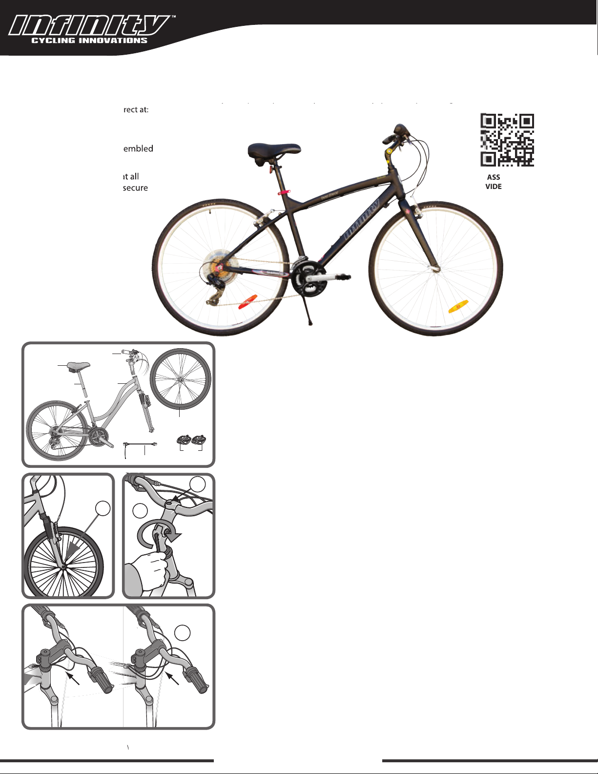
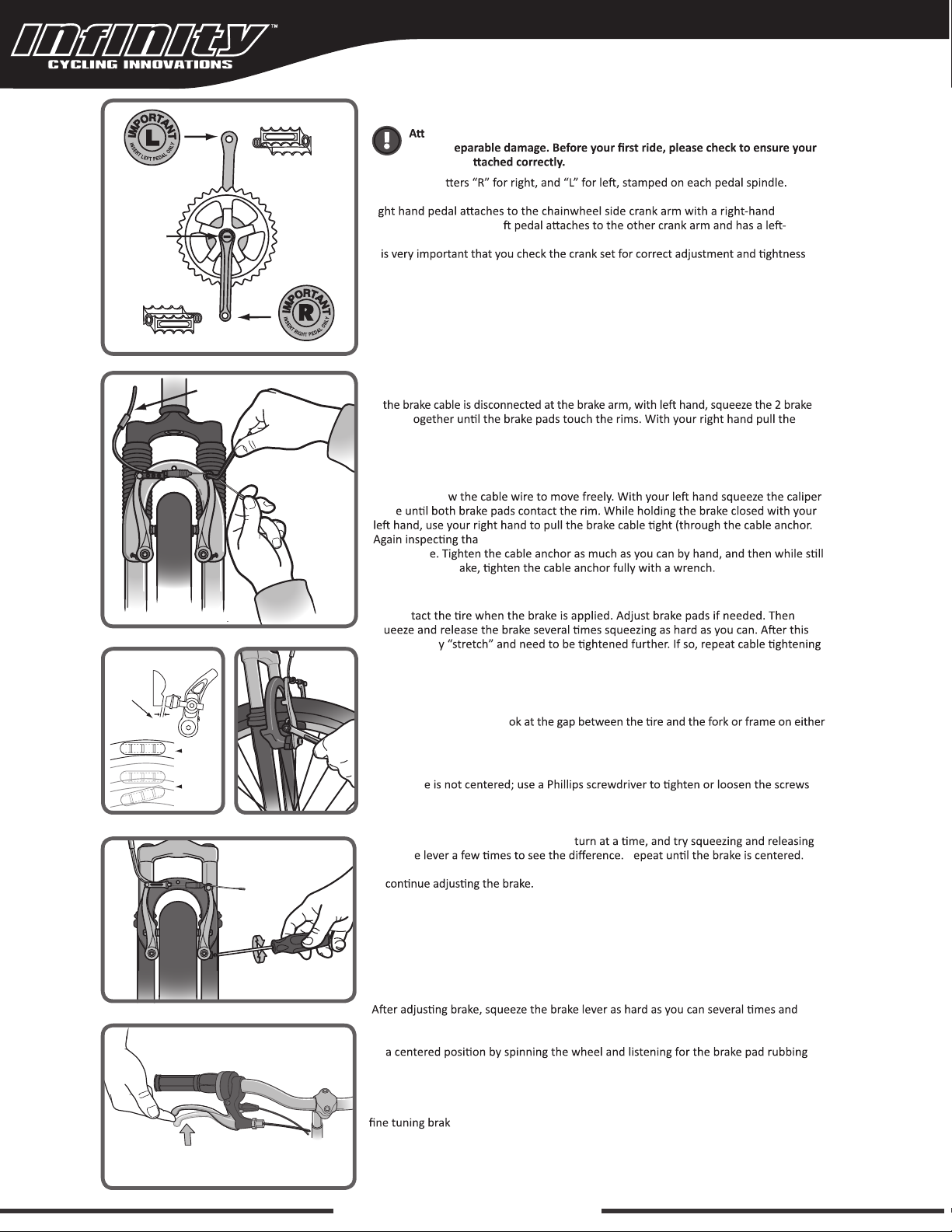
manuals.online logo
Brands
  1. Home
  2. •
  3. Brands
  4. •
  5. Infinity
  6. •
  7. Bicycle
  8. •
  9. Infinity Boss.three 700c User manual

Infinity Boss.three 700c User manual

www.infinitycycleworks.com
copyright 2017 - Infinity Cycle Works Ltd.
Here is a picture of your assembled
bicycle.
Be sure to double check that all
quick release and bolts are secure
before riding.
Always wear a helmet.
TOOLS FOR ASSEMBLY ARE INCLUDED
Your new bicycle was assembled and tuned in the factory and then partially disassembled for shipping. The following instructions will enable you to
prepare your bicycle for years of enjoyable cycling. For more details on inspection, lubrication, maintenance and adjustment of any area, please refer
to the relevant sections in your owner’s manual. Should you require replacement parts or have any questions pertaining to the assembly of your
bicycle, call our service line direct at:
ASSEMBLY
VIDEO LINK
Boss.three 700c Men’s Hybrid Bicycle
CorrectIncorrect
AB
D
C
GETTING STARTED
HANDLEBAR ASSEMBLY
Remove all protective packaging from the handlebar assembly, if not already done.
Turn the fork of the bicycle to face forward. (Note that "forward" means that the wheel
mounting slots are in the furthest forward position, so the wheel axle will be in front of
the fork when assembled.) Look for removable decal and information card on the fork
showing the proper direction. (A)
If your model comes equipped with gears and/or handbrakes, you will need to be sure
that the brake cables and shift cables are properly routed. Position the handlebar
assembly as if you were going to install it and take a look at the cables. They should
run in a smooth arc from the shifter or brake lever to the front brakes or cable stop on
the frame. If they are twisted or kinked, the shifting and braking will not work. Rotate
the handlebars around until the cables are taking the smoothest route. (D)
Loosen the center bolt (B) enough so that the wedge and stem can slide into the fork
steer tube. Lower the stem until the mark that says "minimum insertion" is no longer
visible. Tighten the stem center bolt so that the handlebar assembly is in line with the
fork. If needed, you can recheck this after the front wheel is installed and re-adjust.
Check handlebar stem clamp bolt (C) to be sure they are properly tightened and
handlebar cannot move. The angle of the handlebar can be adjusted. To adjust: loosen
all of the handlebar stem clamping bolts and rotate the handlebar to the desired
angle. Be sure that the handlebar stays centered in the stem. Re-tighten the bolts a
little at a time, being sure that the gap between the stem cap and stem stays even.
Repeat tightening each bolt a little bit until handlebar is secure.
Open the carton from the top and carfully remove the bicycle. Now remove all ties and
protective wrapping making note of parts as you go along. Do not discard packing
material until assembly is complete to ensure no required parts are accidentally
discarded.
Pedals
Frame
Handlebar assembly
Front wheel
Quick Release
Seat
Seat post
Quick Release Wheels
1. Locate the quick release skewer from the small parts carton of your bicycle. Some
bicycle so tha
2. Unscrew the lock nut from the quick release skewer, remove outer spring and slide
th
bike (the side opposite the chain).
3. Install spring and then start to thread the lock nut back onto the skewer, but do not
en too far.
4. Slide the wheel into the fork wheel slots and be sure that the wheel is centered.
5. Inspect the handle, not
the lock nut, st
with the fork.
6.
try again.
7.
NOT a
closing, the lock nut (opposit
Next go back and check that the handlebars are perpendicular to the front wheel,
go back to handlebar assembly and re-adjust if needed.
All quick release levers should be inspected before every ride to be sure
they are fully closed and secure. Failure to properly close a quick release
lev
Make sure the wheel is properly seated and the quick release is
properly closed.
Close
SADDLE ASSEMBLY
The seat pos
be seen. The quick release mechanism mus
ailure to do this may cause loss of
bicycle control.
The saddle assembly should be adjusted with the saddle centered on the rails and
level. Locate the saddle assembly and insert into the frame. It is recommended to add
some grease to all threads and binders on a bicycle, especially on the outside of the seat
po
Bolted Seat Clamp
If your bicy
the clamp so that the saddle ma
th
mark on the seat post. Riding a bicycle with the seat post above this line is dangerous
and can cause injury to the rider or damage to the bicycle or create an unstable riding
t.
Quick Release Seat Clamp
If your bicycle has a seat clamp with a quick release, adjust seat to desired height, and
up or down. If the saddle mo
th
mark on the seat post. Riding a bicycle with the seat post above this line is dangerous
and can cause injury to the rider or damage to the bicycle or create an unstable riding
t.
Seat clamp
Quick release
Seat post
Rails
NOTE:Comfort Series bicycles may be equipped with a stem that has an adjustable angle.
, these stems will require angling the stem to the
bolt. Failure to do this may cause loss of steering control.
If
to o
in
front wheel. Try turning the handlebar. If you can turn it without turning
the front wheel, the stem is too loose. Re-align the handlebar with the
fron
FRONT WHEEL
www.infinitycycleworks.com
copyright 2017 - Infinity Cycle Works Ltd.
PEDALS AND CRANKS
achment of an incorrect pedal into a crank arm can strip pedal threads and
cause irr
pedals are a
Look for the le
Start each pedal spindle by hand to avoid stripping the threads. (Note that the
ri
(clockwise) thread. The le
hand (counter-clockwise thread). Tighten with a 15mm narrow open ended wrench.
It
before riding your bicycle.
Dust
cap
Linear Pull Brakes
If
halves t
brake cable so that the stepped end of the “noodle” can be inserted into the brake
carrier.
Brake adjustment
Check to be sure the cableis seated in the brake lever. Loosen the cableanchor bolt just
enough to allo
brak
t the cable end is seated in the brake lever, and the barrel adjuster
of the brak
squeezing the br
Noodle
Check the brake pads to be sure they are aligned with the rim, and that they do
not con
sq
the cable ma
steps.
Centering brake
If you squeeze the brake and one side moves more than the other, or one side does not
move at all, then the brake is not centered, or the wheel is not centered.
if the wheel is centered. Lo
side. If it is not even, loosen wheel axle nuts and center the wheel, then proceed to
centering the brake.
Brake pad aligned
with the rim surface
Pad and
rim should
be parallel
1-2 mm
Incorrect
Correct
First determ eni
www.infinitycycleworks.com
copyright 2017 - Infinity Cycle Works Ltd.
If the brak
on either side of the linear pull brake where they mount to the frame or fork. If you
turn the screw clockwise it will increase spring tension on that side, counter clockwise
to decrease spring tension. Start by increasing tension on the side that is not moving or
not moving enough. Turn only about ½
the brak R If
you run out of adjustment, you can go to the other side and loosen the screw slightly
to When the brake is correctlyadjusted, both sides shou dl
move evenly when the brake lever is squeezed, and when released, the wheel should
rotate with no brake shoe contact.
Brake is correctly adjusted when:
• Both brake pads move away from the rim equally when the brake is released.
• The brake pads do not drag on the rim when the brake is open.
• When the brake is applied, the brake pads contact the rim before the brake
lever reaches about 1/3 of the way to the handlebar
re-inspect the brake pads, centering, and brake lever travel. If the brake pads are no
longer square to the rim, repeat brake pad adjustments. Be sure that brake pads return
to
the rim on either side. Readjust as needed. Check that the brake cable tension allows
the brake lever about 1/3 of the travel before the brake pads contact the rim. If the
cablehas stretched or slipped, readjust brake cable tension by loosening cable anchor
bolt and pulling more cable through the anchor or use brake adjustment barrels for
e cable tension.
SERVICE & TECHNICAL SUPPORT
TOLL FREE 1.855.521.1127
Monday - Friday 8:00 a.m. to 5:00 p.m. Pacific Time
Do not ride a bicycle tha
adjustments may cause irreparable damage to the bicycle and/or bodily
injury
load, nor pedal backwar
the chain and cause serious damage to the bicycle and/or rider.
screw
Chainguide clearance
of 1-3mm
Outer chainguide
Inner
chainguide
Cable
anchor bolt
DERAILLEUR
Although the fron
need to inspect and readjust both before riding the bicycle.
Rear Derailleur
the smallest sprocket. Adjust the High limit screw so the guide pulley and the smallest
sprock
th
qu
ge
will loosen the cable tension and move the chain away from the wheel, while turning
coun
Sh
Low limit scr
are aligned v
gear is achie
cable is adjusted properly.
Ensure all bolts ar
Freewheel Outer side of top gear
Pulley
adjustment
screw
Adjustment
screws
SIS cable
adjuster
Tension
Pulley
Guide
Pulley
High gear
adjustment
screw
Low gear
adjustment
screw
Barrel
adjuster
FINAL CHECK
may blo
Tighten both front/rear wheel axle nuts or the quick release mechanism securely. Failure to do this may cause the
fron
•
are c
any necessary adjustments.
•
•
•
• Correct maintenance of your bicycle will ensure many years of happy riding. Service your bicycle regularly by referring to the relevant
www.infinitycycleworks.com
copyright 2017 - Infinity Cycle Works Ltd.
FRONT DERAILLEUR
Shi both shiers to the smallest number indicated and place the chain on the
corresponding cog and chainring. Disconnect the front derailleur cable from the cable
anchor bolt. Check the posion of the front derailleur; it should be parallel with the outer
chainring and clear the largest chainring by 1-3mm whenfully engaged. With the chain on
the smallest chainring in front and the largest cog in back, adjust the Low limit screw so
the chain is centered in teh front derailleur cage. Reconnect the cable, pull any slack out,
and ghten the anchor bolt securely. Shi the font shier to the largest chainring. If the
chain does not go onto the largest chainring, turn the high limit screw in 1/4 turn
increments counter-clockwise unl the chain engages the largest chainring. If the chain
falls off the largest chainring, and into the pedals, adjust the HIGH limit screw in 1/4 turn
increments clockwise unl the chain no longer falls off. Shi through every gear, using the
barrel adjusters to fine tune each transion. The barrel adjuster for the front derailleur is
located on the front shier where the cable comes out of the shier. Clockwise loosens
the cable tension and directs the chain closer to the frame, while counter-clockwise
ghtens the cable tension and directs the chain away from the frame.

Other Infinity Bicycle manuals

Infinity Crazyhorse XM3 ST User manual

Infinity

Infinity Crazyhorse XM3 ST User manual

Infinity Backroads User manual

Infinity

Infinity Backroads User manual

Infinity MOUNTAIN BICYCLE User manual

Infinity

Infinity MOUNTAIN BICYCLE User manual

Infinity Boss.three User manual

Infinity

Infinity Boss.three User manual

Popular Bicycle manuals by other brands

Mongoose MULTI SPEED owner's manual

Mongoose

Mongoose MULTI SPEED owner's manual

WINDGOO Technology T8 user manual

WINDGOO Technology

WINDGOO Technology T8 user manual

Scott GENIUS LT owner's manual

Scott

Scott GENIUS LT owner's manual

DAHON P user manual

DAHON

DAHON P user manual

Yeti KoKoPelli owner's manual

Yeti

Yeti KoKoPelli owner's manual

Kalkhoff Pedelec Groove user manual

Kalkhoff

Kalkhoff Pedelec Groove user manual

Moustache Lundi 27 user manual

Moustache

Moustache Lundi 27 user manual

Scott SPARK owner's manual

Scott

Scott SPARK owner's manual

LFB CT26-15 user manual

LFB

LFB CT26-15 user manual

GLOBBER TRIKE owner's manual

GLOBBER

GLOBBER TRIKE owner's manual

FLX F2 user manual

FLX

FLX F2 user manual

Adomeit Group Veleon user manual

Adomeit Group

Adomeit Group Veleon user manual

SJOEF BIS256 instruction manual

SJOEF

SJOEF BIS256 instruction manual

Yuba Mundo Assembly instructions

Yuba

Yuba Mundo Assembly instructions

KENT Glendale 32656 Assembly manual

KENT

KENT Glendale 32656 Assembly manual

Evelo Delta Assembly guide

Evelo

Evelo Delta Assembly guide

ELECTRIC WHEELS EW-620 Assembly and setup instructions

ELECTRIC WHEELS

ELECTRIC WHEELS EW-620 Assembly and setup instructions

Electric Bike Company C manual

Electric Bike Company

Electric Bike Company C manual

manuals.online logo
manuals.online logoBrands
  • About & Mission
  • Contact us
  • Privacy Policy
  • Terms and Conditions

Copyright 2025 Manuals.Online. All Rights Reserved.