Infinity Crazyhorse XM3 ST User manual

TOOLS FOR ASSEMBLY
bicycle, call the service line direct at:
Tools Required:
• Phillips head screw driver
• 4mm, 5mm, 6mm and 8mm Allen keys
• Adjustable wrench or a 9mm, 10mm, 14mm and 15mm open and box end wrenches
• A pair of plier
GETTING STARTED
Op
wrapping from the bicycle. Inspect the bicycle and all accessories and parts for possible
shortages. It is recommended that the threads and all moving parts in the parts package
be lubrica
complete to ensure that no required parts are accidentally discarded. Assemble your
bicycle following the steps that pertain to your model.
NOTE: Y
ones illustrated.
HANDLEBAR ASSEMBLY
Remo
Turn the fork of the bicycle to face forward. Note that “forward” means that the wheel
the fork when assembled.
Check handlebar st
handlebar can not move. The angle of the handlebar can be adjusted. To adjust; loosen
all of the handlebar stem clamping bolts, and rotate the handlebar to the desired angle.
Be sure tha
t the gap between the stem cap and stem stays even. Repeat
Models with gear and/or brake cables:
Locate the handlebar assembly. If your model bicycle comes equipped with gears
and/or handbr
properly r
tak
lever to the front brake or cable stop on the frame. If they are twisted or kinked, the
taking the smoothest route.
CorrectIncorrect
CorrectIncorrect
www.infinitycycleworks.com
copyright 2018 - Infinity Cycle Works Ltd.
Using the provided hex wrench, remove the four screws holding the stem clamp in place (Fig. A).
Place and center handlebars within the stem (some have centerline marks), and replace screws
(Fig. B).
Tighten with the provided hex wrench (Fig. C). Make sure that the gap between the stem is
roughly the same on the top and boom (Fig. D, i), and the handlebars are at a comfortable
riding angle (Fig. d, ii).
AB
C
D
ii
i
INFINITY MODEL: Crazyhorse XM3 ST
Here is a picture of your assembled bicycle.
Be sure to double check that all bolts are
secure before riding.
Always wear a helmet.

t.
www.infinitycycleworks.com
copyright 2018 - Infinity Cycle Works Ltd.
DISC BRAKES
Your bike is fied with a front disc brake, and the components should already be aached.
However, please check all connecons before aempng to ride the bicycle. Secure ghtly
the 6 bolts that hold the disc to the front wheel hub and the 2 bolts that hold the brake
mechanism to the fork. Double check that the front hub is inserted into the fork drop outs
correctly and that the quick release is closed and secure.
DISC GETS HOT! Severe injury could result from contact with the hot disc! Mind
your legs, as well as your hands.
If your bike is equipped with a front disc brake, be careful not to damage the
disc, caliper or brake pads when re-inserng the disc into the caliper. Never
acvate a disc brake’s control lever unless the disc is correctly inserted in the
caliper.
These brakes require breaking in! Ride and use the brakes gently for a few miles
before using the brakes in downhill condions, for sudden stops, or any other
serious braking. Please be aware that your brake system will change in
performance throughout the wear-in process. The disc brake should be cleaned
before the first ride using rubbing alcohol. NEVER use oil or similar products to
clean your disc brake system.
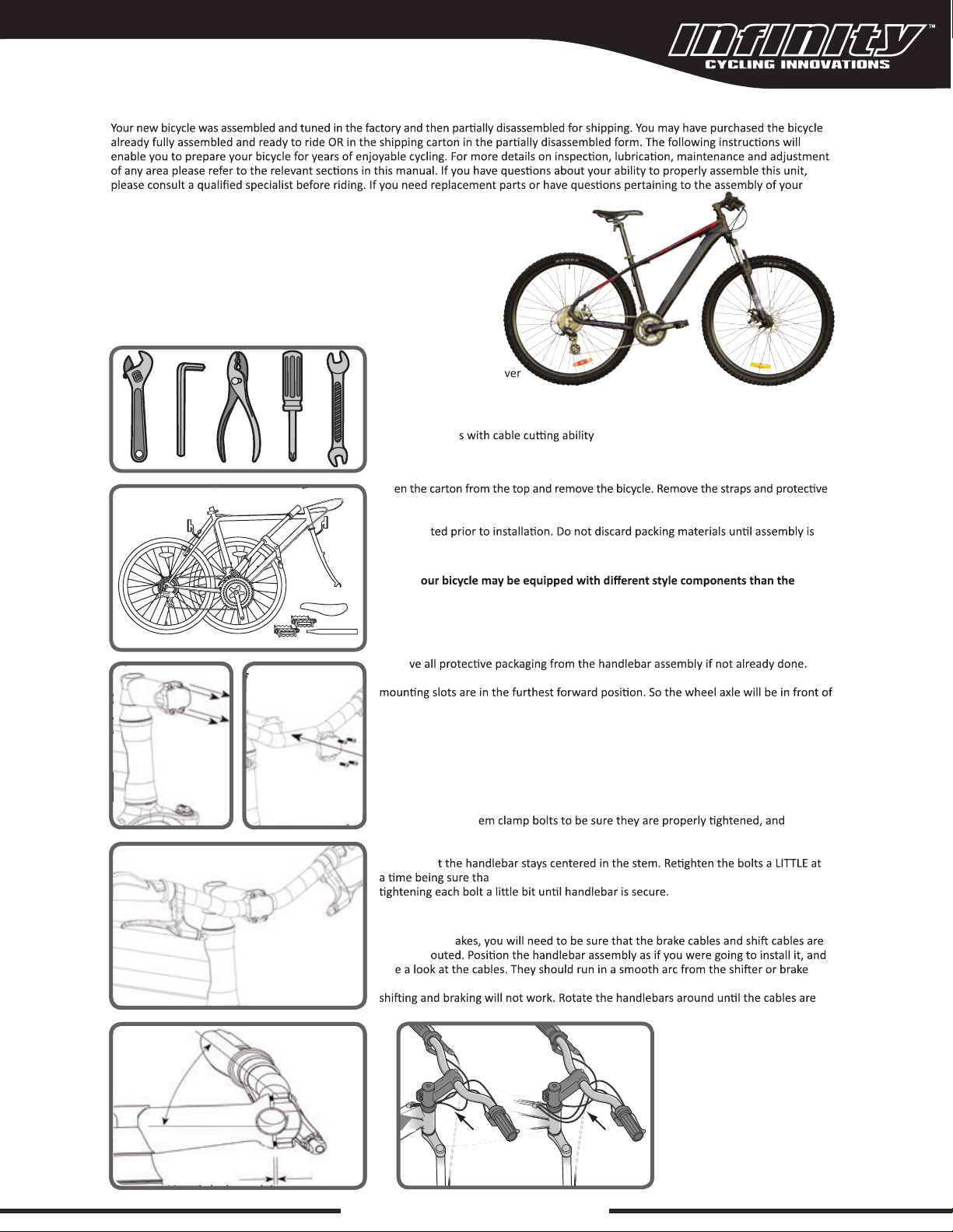
FRONT WHEEL
1. Locate the quick release skewer from the small parts carton of your bicycle.
2. Unscrew the lock nut from the quick release skewer, remove outer spring and slide the
skewer through the front wheel axle.
3. Install spring and then start to thread the lock nut back onto the skewer, but do not
ghten too far.
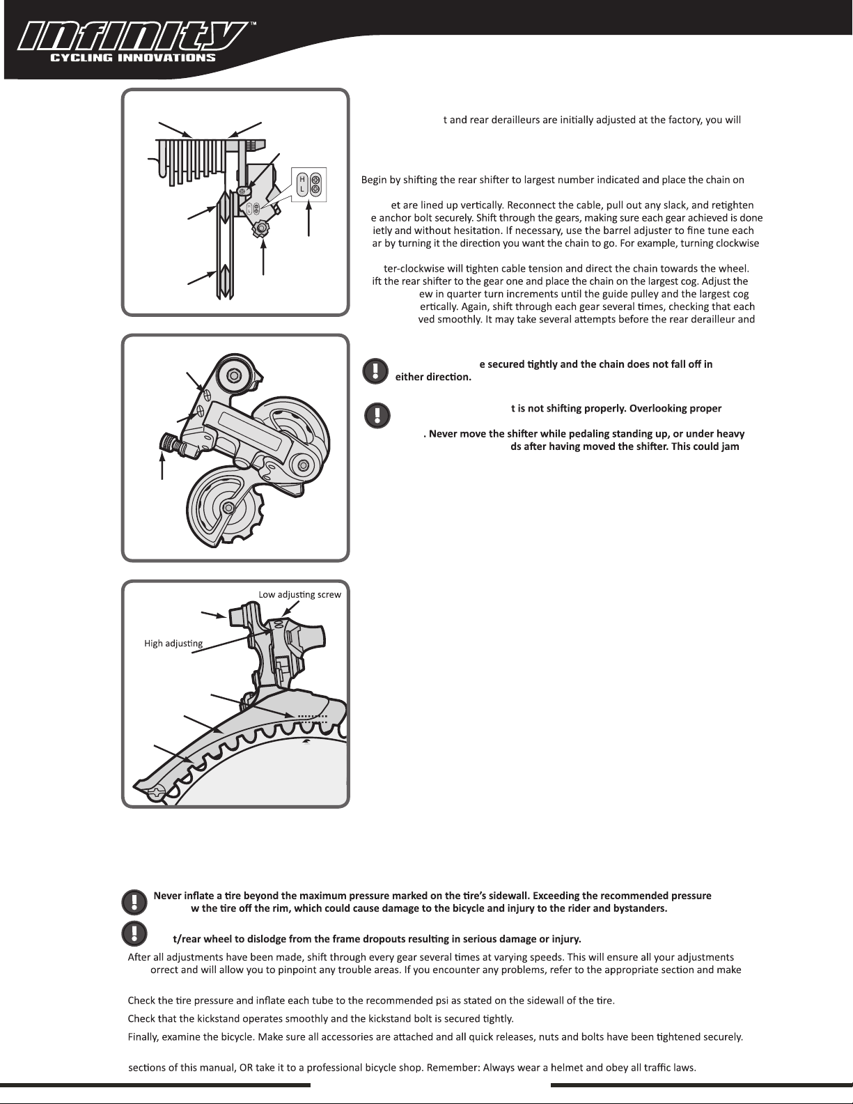
4. Slide the wheel into the fork wheel slots and be sure that the wheel is centered. Your
front wheel has a disc brake, insert the disc rotor into the slot on the caliper body as
you insert the wheel axle into the fork drop out.
5. The handle on the quick release has an “open” and a “closed” posion. Move the
handle so it is in the “open” posion. With one hand on the handle and one hand on
the lock nut, start to hand ghten the lock nut unl you start to feel some resistance
with the fork.
6. Try to close the handle. If it closes easily, open it up, and ghten the lock nut further. If
it is too difficult to close, open the handle, and loosen the lock nut try again.
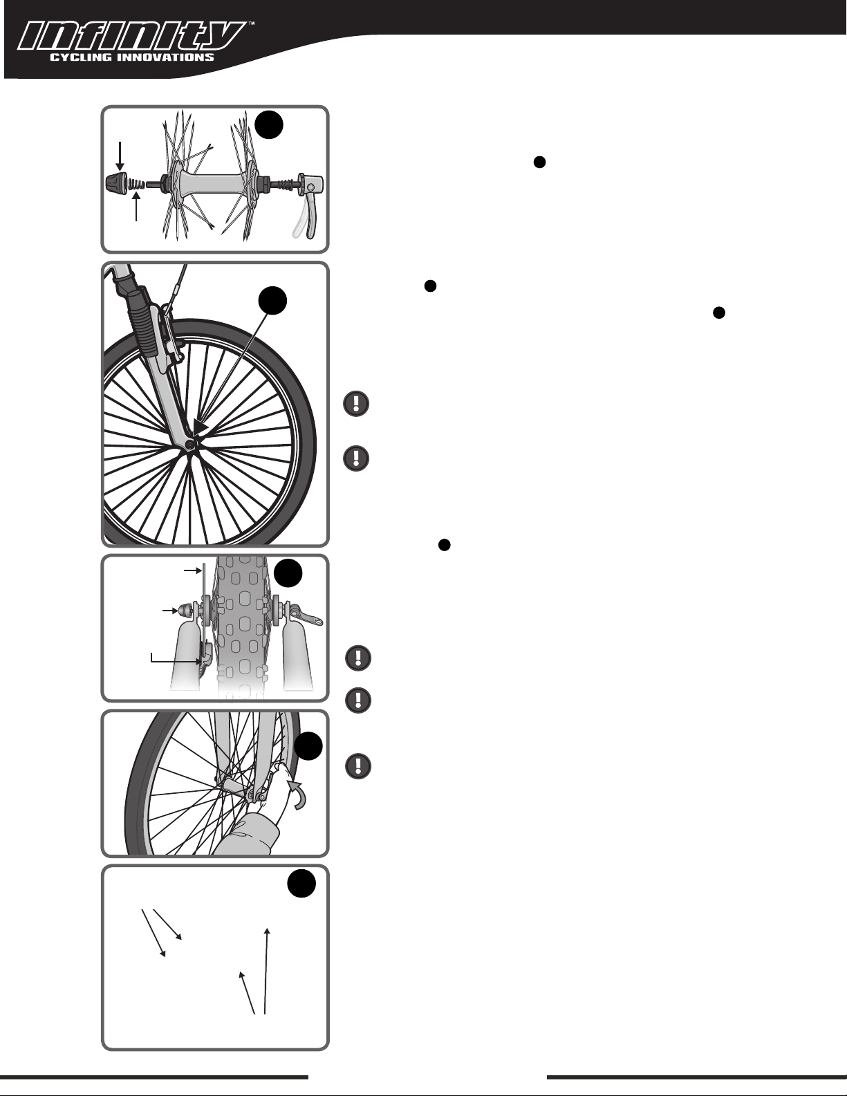
7. The quick release handle should be difficult to push closed with your palm, but should
be possible. Pracce opening and closing the handle unl you feel comfortable. DO NOT
aempt to ghten the wheel by turning the handle to ghten; the handle is for securing
the wheel, use the lock nut for adjusng tension.
All quick release levers should be inspected before every ride to be sure they are
fully closed and secure. Failure to properly close the quick release lever can cause
loss of control of the bicycle resulng in injury or death.
Make sure the wheel is properly seated and the quick release is properly closed.
Lock
Nut
Quick release
skewer
Outer
Spring
1
1
3
4
5
2
3
4
Lock Nut
Open
Disc rotor
Disc brake
caliper body
Close
Disc Bolts
Brake Mechanism
5

PEDALS AND CRANKS
achment of an incorrect pedal into a crank arm can strip pedal threads and
cause irr
pedals are a
Look for the le
Start each pedal spindle by hand to avoid stripping the threads. (Note that the
ri
(clockwise) thread. The le
hand (counter-clockwise thread). Tighten witha15mmnarrow open ended wrench.
It
before riding your bicycle.
Dust
cap
SADDLE ASSEMBLY
The seat pos
be seen. The quick release mechanism mus
ailure to do this may cause loss of
bicycle control.
The saddle assembly should be adjusted with the saddle centered on the rails and
level. Locate the saddle assembly and insert into the frame. It is recommended to add
some grease to all threads and binders on a bicycle, especially on the outside of the seat
po
Bolted Seat Clamp
If your bicy
the clamp so that the saddle ma
th
mark on the seat post. Riding a bicycle with the seat post above this line is dangerous
and can cause injury to the rider or damage to the bicycle or create an unstable riding
t.
Quick Release Seat Clamp
If your bicycle has a seat clamp with a quick release, adjust seat to desired height, and
up or down. If the saddle mo
th
mark on the seat post. Riding a bicycle with the seat post above this line is dangerous
and can cause injury to the rider or damage to the bicycle or create an unstable riding
Seat clamp
Quick release
Seat post
Rails
www.infinitycycleworks.com
copyright 2018 - Infinity Cycle Works Ltd.

SERVICE & TECHNICAL SUPPORT
TOLL FREE 1.855.521.1127
Monday - Friday 8:00 a.m. to 5:00 p.m. Pacific Time
FRONT DERAILLEUR
Shi both shiers to the smallest number indicated and place the chain on the
corresponding cog and chainring. Disconnect the front derailleur cable from the cable
anchor bolt. Check the posion of the front derailleur; it should be parallel with the outer
chainring and clear the largest chainring by 1-3mm whenfully engaged. With the chain on
the smallest chainring in front and the largest cog in back, adjust the Low limit screw so
the chain is centered in teh front derailleur cage. Reconnect the cable, pull any slack out,
and ghten the anchor bolt securely. Shi the font shier to the largest chainring. If the
chain does not go onto the largest chainring, turn the high limit screw in 1/4 turn
increments counter-clockwise unl the chain engages the largest chainring. If the chain
falls off the largest chainring, and into the pedals, adjust the HIGH limit screw in 1/4 turn
increments clockwise unl the chain no longer falls off. Shi through every gear, using the
barrel adjusters to fine tune each transion. The barrel adjuster for the front derailleur is
located on the front shier where the cable comes out of the shier. Clockwise loosens
the cable tension and directs the chain closer to the frame, while counter-clockwise
ghtens the cable tension and directs the chain away from the frame.
Do not ride a bicycle tha
adjustments may cause irreparable damage to the bicycle and/or bodily
injury
load, nor pedal backwar
the chain and cause serious damage to the bicycle and/or rider.
screw
Chainguide clearance
of 1-3mm
Outer chainguide
Inner
chainguide
Cable
anchor bolt
DERAILLEUR
Although the fron
need to inspect and readjust both before riding the bicycle.
Rear Derailleur
the smallest sprocket. Adjust the High limit screw so the guide pulley and the smallest
sprock
th
qu
ge
will loosen the cable tension and move the chain away from the wheel, while turning
coun
Sh
Low limit scr
are aligned v
gear is achie
cable is adjusted properly.
Ensure all bolts ar
Freewheel Outer side of top gear
Pulley
adjustment
screw
Adjustment
screws
SIS cable
adjuster
Tension
Pulley
Guide
Pulley
High gear
adjustment
screw
Low gear
adjustment
screw
Barrel
adjuster
FINAL CHECK
may blo
Tighten both front/rear wheel axle nuts or the quick release mechanism securely. Failure to do this may cause the
fron
•
are c
any necessary adjustments.
•
•
•
• Correct maintenance of your bicycle will ensure many years of happy riding. Service your bicycle regularly by referring to the relevant
www.infinitycycleworks.com
copyright 2018 - Infinity Cycle Works Ltd.
This manual suits for next models
1
Table of contents
Other Infinity Bicycle manuals