Infinium OMNI Express User manual

- I
037.007.0001 Rev.2
Doc ID: IFU-OMNI-7002
OMNI Express
Patient Monitor
USER’S MANUAL
037.007.0001 Rev.2

- II
037.007.0001 Rev.2
Doc ID: IFU-OMNI-7002
Infinium Medical Inc.
Website: www.infiniummedical.com
Address: 12151 62nd St North #5 Largo Fl, 33773 USA
Toll Free (US call only): 866-918-8434
International: 1-727-531-8434
Fax: 1-727-531-8436
To obtain information about a warranty, if any, for this product, contact Infinium Medical Inc,
Technical Services or your local Infinium Medical, Inc. representative.
PHASEIN is a trademark of PHASEIN AB
RESPIRONICS is a trademark of PHILIPS RESPIRONICS
Masimo is a trademark of Masimo SET
Nellcor is a trademark of NELLCOR OXIMAX

User’s Manual of OMNI Express Patient Monitor
- III
037.007.0001 Rev.2
CONTENTS
SAFETY INFORMATION...............................................................................................................1
INTRODUCTION ............................................................................................................................4
INTENDED USE......................................................................................................................4
ABOUT THIS MANUAL.........................................................................................................4
CONTROLS, INDICATORS, AND SYMBOLS..............................................................................5
FRONT PANEL........................................................................................................................5
LEFT SIDE PANEL..................................................................................................................6
RIGHT SIDE PANEL...............................................................................................................6
REAR PANEL ..........................................................................................................................7
SYMBOLS................................................................................................................................8
DISPLAY SCREEN PARTITION...................................................................................................10
TWO WAVEFORMS DISPLAY MODE................................................................................10
THREE WAVEFORMS DISPLAY MODE ............................................................................10
WAVEFORM AREA...............................................................................................................11
PARAMETER AREA.............................................................................................................11
MESSAGE AREA ..................................................................................................................11
SYSTEM SETUP............................................................................................................................12
FACTORY SEVICING SETUP..............................................................................................12
OPTIONAL MODULE...........................................................................................................13
WAVEFORM SELECT...........................................................................................................13
PRINTER................................................................................................................................13
CONFIG MANAGER.............................................................................................................14
LANGUAGE SETUP .............................................................................................................14
DEMO DISPLAY ...................................................................................................................14
OTHER SETUP......................................................................................................................15
SCREEN CAL ........................................................................................................................15
HOW TO MONITOR .....................................................................................................................16
ALARM & SOUND .......................................................................................................................17
ALARM..........................................................................................................................................17
ALARM SETUP.....................................................................................................................17
VISUALALARM INDICATORS ..........................................................................................17
ALARM SUSPEND ...............................................................................................................18
ALARM SWITCH..................................................................................................................18
SOUND...........................................................................................................................................19
ALARM SOUND ...................................................................................................................19
HEART-BEAT (PULSE-TONE).............................................................................................19
KEY BEEPS............................................................................................................................19
SILENCE................................................................................................................................19
ECG MONITORING......................................................................................................................20
ELECTRODE INSTALLATION............................................................................................20

User’s Manual of OMNI Express Patient Monitor
- IV
037.007.0001 Rev.2
CABLE AND LEADWIRE INSTALLATION .......................................................................21
ECG SETUP ...........................................................................................................................22
ST-SEGMENTANALYSIS....................................................................................................24
ARRHYTHMIAANALYSIS..................................................................................................26
ERROR MESSAGES OF ECG MONITORING....................................................................27
MAINTENANCE AND CLEANING.....................................................................................27
RESP MONITORING.....................................................................................................................29
RESP ELECTRODE INSTALLATION..................................................................................29
RESP SETUP..........................................................................................................................29
MAINTENANCE AND CLEANING.....................................................................................30
SPO2 MONITORING.....................................................................................................................31
SPO2 MONITORING PRINCIPLE........................................................................................31
SPO2 SENSOR INSTALLLATION .......................................................................................31
SPO2 SETUP..........................................................................................................................31
MEASUREMENT LIMITATIONS ........................................................................................33
SPO2 ERROR MESSAGES...................................................................................................34
MASIMO INFORMATION....................................................................................................34
NELLCOR INFORMATION..................................................................................................36
NIBP MONITORING.....................................................................................................................37
NIBP MONITORING PRINCIPLE........................................................................................37
NIBP CUFF FITTING............................................................................................................37
NIBP MONITORING INITIALIZATION..............................................................................38
NIBP SETUP ..........................................................................................................................38
NIBP LIST OBSERVATION...................................................................................................41
MEASUREMENT LIMITATIONS ........................................................................................41
NIBP ERROR MESSAGES....................................................................................................42
MAINTAINENCE AND CLEANING....................................................................................42
TEMP MONITORING ...................................................................................................................43
THEORY OF OPERATION....................................................................................................43
TEMP SENSOR INSTALLATION.........................................................................................43
TEMP SETUP.........................................................................................................................43
TEMP ERROR MESSAGES..................................................................................................44
MAINTAINENCE AND CLEANING....................................................................................44
QUICK TEMP MONITORING (OPTIONAL) ..............................................................................45
ABOUT BODY TEMPERATURES.......................................................................................45
GENERAL INFORMATION..................................................................................................45
SAFETYAND WARNING.....................................................................................................46
INSTRUCTION FOR USE.....................................................................................................46
QTEMP PARAMETER SETUP .............................................................................................50
MAINTAINENCE AND CLEANING....................................................................................51

User’s Manual of OMNI Express Patient Monitor
- V
037.007.0001 Rev.2
ETCO2 MONITORING (OPTIONAL)..........................................................................................52
THEORY OF OPERATION....................................................................................................52
WARNINGS............................................................................................................................52
ABBREVIATIONS AND TERMINOLOGY .........................................................................53
ZEROING THE CO2 MODULE............................................................................................53
PATIENTAND TUBING PREPARATION............................................................................53
ETCO2 SETUP.......................................................................................................................55
ADVANCED SETUP..............................................................................................................57
CALIBRATION......................................................................................................................58
STATUS/ERROR MESSAGES..............................................................................................58
MAINTENANCE AND CLEANING.....................................................................................59
ANESTHETIC AGENT MONITORING (OPTIONAL, PHASEIN).............................................60
PHASEIN IRMA™ MAINSTREAM PROBE...............................................................................60
INTRODUCTION ..................................................................................................................60
SAFETY .................................................................................................................................61
SYSTEMASSEMBLY INSTRUCTION................................................................................61
ZEROING PROCEDURE ......................................................................................................63
ALARMS................................................................................................................................64
CLEANING............................................................................................................................65
MAINTENANCE ...................................................................................................................65
PHASEIN ISA™ SIDESTREAM ANALYZER.............................................................................66
INTRODUCTION ..................................................................................................................66
SAFETY .................................................................................................................................67
ANALYZER SYSTEM SET-UP.............................................................................................68
PRE-USE CHECK..................................................................................................................68
CONSUMABLE.....................................................................................................................69
ALARMS................................................................................................................................71
AUTOMATIC ZEROING.......................................................................................................72
CLEANING............................................................................................................................72
MAINTENANCE ...................................................................................................................72
MAC (Minimum Alveolar Concentration) CACULATION ...................................................73
ADVERSE EFFECTS ON PERFORMANCE .......................................................................75
ANESTHETIC AGENT DISPLAY ........................................................................................75
ANESTHETIC AGENT SETUP.............................................................................................76
PATIENT INFORMATION ADMINISTRATION..........................................................................78
PATIENT BASIC INFORMATION SETUP...........................................................................78
ADD NEW PATIENT.............................................................................................................79
DELETE PATIENT.................................................................................................................79
TREND...........................................................................................................................................80
TREND OBSERVATION .......................................................................................................80

User’s Manual of OMNI Express Patient Monitor
- VI
037.007.0001 Rev.2
TIME SETUP..........................................................................................................................80
MARK EVENT SETUP .........................................................................................................81
TRENDING INTERVAL........................................................................................................82
TREND GRAPH ANALYSIS.................................................................................................82
TABULAR TREND ANALYSIS............................................................................................82
ALARM EVENT....................................................................................................................83
LAST WAVEFORM ...............................................................................................................83
RECALL DATA..............................................................................................................................85
RECALL DATA STORAGE...................................................................................................85
RECALL DATA DISPLAY.....................................................................................................85
RECALL OPERATION DESCRIPTION ...............................................................................85
RS-232 INTERFACE......................................................................................................................87
OVERVIEW............................................................................................................................87
CABLE CONNECTION.........................................................................................................87
EXPORTING TREND DATA.................................................................................................87
PRINTER (OPTIONAL) ................................................................................................................88
PRINTER SETUP...................................................................................................................88
PRINT REAL-TIME WAVEFORM........................................................................................88
PRINT TABULAR TREND....................................................................................................88
GRID OUTPUT......................................................................................................................89
PRINTALARM EVENT........................................................................................................89
PRINT EVENT LIST..............................................................................................................89
PRINT EXPLANTION...........................................................................................................89
WAVEFORM PRINT EXPLANATION .................................................................................90
BATTERY OPERATION................................................................................................................91
INTRODUCTION ..................................................................................................................91
CONDITIONING A BATTERY .............................................................................................91
BATTERY RECYCLE............................................................................................................92
DISPOSAL OF DEVICE COMPONENTS....................................................................................92
PERIODIC SAFETY CHECKS......................................................................................................93
CLEANING....................................................................................................................................93
SPECIFICATIONS .........................................................................................................................94
ACCESSORIES............................................................................................................................103
WARNNING.........................................................................................................................103
ECG.......................................................................................................................................103
SpO2 .....................................................................................................................................103
NIBP .....................................................................................................................................103
TEMP....................................................................................................................................104
ADDITIONAL......................................................................................................................104
EMC..............................................................................................................................................105
NOTE:...................................................................................................................................105


User’s Manual of OMNI Express Patient Monitor
- VIII
037.007.0001 Rev.2
FIGURES
Figure 1: Front Panel.................................................................................................................5
Figure 2: Left Side Panel...........................................................................................................6
Figure 3: Right Side Panel........................................................................................................6
Figure 4: Rear View for Main Unit...........................................................................................7
Figure 5: Display Screen for Two Waveforms........................................................................10
Figure 6: Display Screen for Three Waveforms......................................................................10
Figure 7: Tree Diagram for System Setup Menu ....................................................................12
Figure 8: Keypad to inputASCIIS..........................................................................................14
Figure 9: 5-lead Electrode Placement .....................................................................................20
Figure 10: C-electrode Placement...........................................................................................21
Figure 11: Tree Diagram for ECG Setup.................................................................................22
Figure 12: Window for ARR Review......................................................................................26
Figure 13: Window for ARR Retail Information.....................................................................27
Figure 14: Tree Diagram for Resp Menu ................................................................................30
Figure 15: Tree Diagram for SpO2Setup Menu......................................................................32
Figure 16: Tree Diagram for NIBP Setup Menu.....................................................................38
Figure 17: Window for NIBP List Observation ......................................................................41
Figure 18: Sketch Map for Replacing The Bladder ................................................................42
Figure 19: Tree Diagram for Temp Setup Menu.....................................................................43
Figure 20: Temperature Site and PatientAge..........................................................................45
Figure 21: Tree Diagram for QTemp Setup Menu..................................................................50
Figure 22: Tree Diagram for EtCO2Setup Menu....................................................................55
Figure 23: Tree Diagram for EtCO2Advanced Setup.............................................................57
Figure 24: Tree Diagram for Multi-Gas Setup Menu..............................................................76
Figure 25: Tree Diagram for Patient Setup .............................................................................78
Figure 26: Tree Diagram for Time Setup................................................................................80
Figure 27: Window for Mark Event Setup..............................................................................81
Figure 28: Window for Event List...........................................................................................81
Figure 29: Window for Trend Graph.......................................................................................82
Figure 30: Window for Basic Parameters Tabular Trend........................................................83
Figure 31: Window for Alarm Event Review..........................................................................83
Figure 32: Window for Last Waveform Review .....................................................................84
Figure 33: Window for Indication Information.......................................................................85
Figure 34: Window for Recall Patient.....................................................................................86
Figure 35: Window for Trend Management with ID...............................................................86
Figure 36: Real-time Waveform Print.....................................................................................88
Figure 37: Basic Tabular Trend Print......................................................................................88
Figure 38:Alarm Event Print..................................................................................................89
Figure 39: Event List Print......................................................................................................89

User’s Manual of OMNI Express Patient Monitor
- 1
037.007.0001 Rev.2
SAFETY INFORMATION
This section contains important safety information relating to general use of the OMNI
Express Patient Monitor. Other important safety information appears throughout the
manual in sections that relate specifically to the precautionary information. Read all text
surrounding all precautionary information.
The OMNI Express can be powered by one internal battery that provides 2 hours of
monitoring from fully charged battery. The batteries are continuously recharged when AC
power is connected to the monitor.
A warning message appears on the screen and an audible alarm sounds when the
remaining battery power is only enough for 15 minutes of operation. The user should
connect the monitor to an external power source to avoid loss of patient monitoring action.
External power sources may be connected, disconnected, and reconnected without
interrupting the monitoring action.
[WARNING]: OMNI Express Patient Monitor should not be used as an apnea monitor.
[NOTE]: Before use, please read this manual carefully.
[WARNING]: The OMNI Express is defibrillator proof. It may remain attached to the
patient during defibrillation or while an electrosurgical unit is in use, but the readings
may be inaccurate during use and shortly thereafter.
[WARNING]: The OMNI Express Patient Monitor is a prescription device and is to be
operated by qualified personnel only.
[WARNING]: Occasionally, electrical signals at the heart do not produce a peripheral
pulse. If a patient’s beat-to-beat pulse amplitude varies significantly (for example,
pulsus alternans, atrial fibrillation, rapid-cycling artificial ventilator), blood pressure and
pulse rate readings can be erratic and an alternate measuring method should be used
for confirmation.
[WARNING]: DO NOT lift the monitor by the sensor cable, blood pressure hose, or
power cord because the cable, lead, or cord could disconnect from the monitor,
causing the monitor to drop on the patient.
[WARNING]: Explosion hazard. DO NOT use the OMNI Express in the presence of
flammable anesthetics or other flammable substance in combination with air,
oxygen-enriched environments, or nitrous oxide.
[WARNING]: The OMNI Express may not operate effectively on patients who are
experiencing convulsions or tremors.
[WARNING]: Disconnect the OMNI Express and sensors during magnetic resonance
imaging (MRI) scanning. Use during MRI could cause burns or adversely affect the
MRI image or the monitor’s accuracy. Also, to avoid burns, remove the sensors from
the patient before conducting MRI.

User’s Manual of OMNI Express Patient Monitor
- 2
037.007.0001 Rev.2
[WARNING]: The user must check the equipment prior to use and ensure its safe and
proper use.
[WARNING]: To ensure that the leakage current protection remains within the
specifications, use only the patient cables supplied with or specifically intended for use
with the OMNI Express Monitors. Carefully route patient cables to reduce the
possibility of patient entanglement or strangulation.
[WARNING]: To ensure patient safety, DO NOT places the monitor in any position that
might cause it to fall on the patient.
[WARNING]: For pacemaker patients, the OMNI Express may continue to count
pacemaker rate during occurrences of cardiac arrest or some arrhythmias. To reduce
the likelihood of this, ensure that the Pacer Detect setting is ON in the ECG menu
when monitoring such patients. DO NOT rely entirely upon the OMNI Express alarms.
Keep pacemaker patients under close surveillance.
[WARNING]: Connection of non-isolated devices to the RS-232 connector may cause
chassis leakage to exceed the specification standards.
[WARNING]: Enclosure leakage current is less than 100 microamperes (µA);
however, always consider additional leakage current that can be caused by other
equipment used on the patient at the same time as these monitors.
[WARNING]: DO NOT use the OMNI Express to monitor patients who are linked to
heart/lung machines.
[WARNING]: DO NOT autoclave, ethylene oxide sterilize, or immerse these monitors
in liquid. Use the cleaning solution sparingly. Excessive solution can flow into the
monitor and cause damage to internal components. Do not use petroleum-based or
acetone solutions, or other harsh solvents, to clean the monitor. These substances
attack the monitor’s materials and device failure can result. Unplug the monitors
before cleaning or disinfecting.
[WARNING]: To prevent electrical hazards to all personnel, these monitors must be
properly grounded. The chassis grounding assembly, Universal Switching Power
Supply, and the power cord supplied with the equipment provide this protection. DO
NOT attempt to undo this protection by modifying the cords or using ungrounded
adapters. DO NOT remove the monitor cover except to replace the battery.
[WARNING]: Do not touch, press, or rub the display panels with abrasive cleaning
compounds, instruments, brushes, rough surface materials, or bring them into contact
with anything that could scratch the panel.
[WARNING]: Connect the monitor only to a three-wire, grounded, hospital-grade
receptacle. The three-conductor plug must be inserted into a properly wired three-wire
receptacle; if a three-wire receptacle is not available, a qualified electrician must install
one in accordance with the governing electrical code.

User’s Manual of OMNI Express Patient Monitor
- 3
037.007.0001 Rev.2
When connecting the OMNI Express to any instrument, verify proper operation before
clinical use. Both the OMNI Express and the instrument connected to it must be
connected to a grounded outlet. Accessory equipment connected to this Patient Monitor
must be certified according to the respective IEC standards (e.g. IEC 60950 for
information technology equipment and IEC 60601-1 for medical electrical equipment).
Furthermore all configurations shall comply with the valid version of the system standard
IEC 60601-1-1.
Any person who connects additional equipment to the signal input or signal output is
responsible to ensure the system complies with the requirements of the valid version of
the system standard IEC 60601-1-1. If you have any questions, please be free to contact
our company or customer service. When in doubt, contact our company or customer
service.
To ensure accurate readings, consider current environmental conditions and the condition
of the patient. See the appropriate sections of the manual for specific safety information
related to these conditions.
[WARNING]:If there is any doubt about the integrity of the protective earth conductor
arrangement, operate the monitor on internal battery power until the AC power supply
protective conductor is fully functional.
[WARNING]: It is possible for the patient to receive a burn due to an improperly
connected electrosurgical unit. Additionally, the monitor could be damaged or
measurement errors could occur. Certain steps can be taken to mitigate against this
problem, such as not using small ECG electrodes, selecting ECG electrode sites
remote from the expected RF paths, using large electrosurgical return electrodes, and
verifying that the electrosurgical return electrode is properly attached to the patient.
[WARNING]:ECG cables may be damaged if they are connected to a patient during
defibrillation. Cables that have been connected to a patient during defibrillation should
be checked for functionality before using again.
[WARNING]:Line isolation monitor transients may resemble actual cardiac waveforms
and thus inhibit heart rate alarms. Such transients may be minimized by proper
electrode and cable placement, as specified in this manual and electrode directions for
use.
[WARNING]:
Defibrillation and Electrosurgery: DO NOT touch the patient, or table, or
instruments, during defibrillation.
After defibrillation, the screen display recovers within 10 seconds if the correct
electrodes are used and applied in accordance with the manufacturer’s instructions.
ECG cables can be damaged when connected to a patient during defibrillation. Check
cables for functionality before using them again.
According to AAMI specifications the peak of the synchronized defibrillator discharge
should be delivered within 60 ms of the peak of the R wave. The signal at the ECG
output on the OMNI Express patient monitors is delayed by a maximum of 30 ms. Your
biomedical engineer should verify that your ECG/Defibrillator combination does not
exceed the recommended maximum delay of 60 ms.
When using electrosurgical (ES) equipment, never place ECG electrodes near to the
grounding plate of the ES device, as this can cause a lot of interference on the ECG
signal.

User’s Manual of OMNI Express Patient Monitor
- 4
037.007.0001 Rev.2
INTRODUCTION
◼INTENDED USE
◼ABOUT THIS MANUAL
INTENDED USE
The OMNI Express Patient Monitor is a comprehensive monitoring system compiling,
processing, analyzing and displaying data from up to nine different patient parameters. It
integrates parameter measuring modules, display and printer in one device, and is
compact, lightweight and portable. Built-in battery facilitates portability.
The purpose and function of the OMNI Express Patient Monitor is to monitor ECG, heart
rate, NIBP (systolic, diastolic, and mean arterial pressures), SpO2, respiration,
temperature, EtCO2and anesthetic gas (AG) for adult, neonate and pediatric patients in
all hospital areas and hospital-type facilities. It may be used during hospital transport and
in mobile, land-based environments, such as ambulances.
ABOUT THIS MANUAL
This manual explains how to set up and use the OMNI Express Patient Monitor. Important
safety information relating to general use of the OMNI Express appears before this
introduction. Other important safety information is located throughout the text where
applicable. Read the entire manual including the Safety Information section before
you operate the monitor.
[WARNING]: The OMNI Express Patient Monitor is intended only as an adjunct in
patient assessment. It must be used in conjunction with clinical signs and symptoms.
User’s Manual of OMNI Express Patient Monitor
- 5
037.007.0001 Rev.2
CONTROLS, INDICATORS, AND SYMBOLS
◼FRONT PANEL
◼LEFT SIDE PANEL
◼RIGHT SIDE PANEL
◼REAR PANEL
◼SYMBOLS
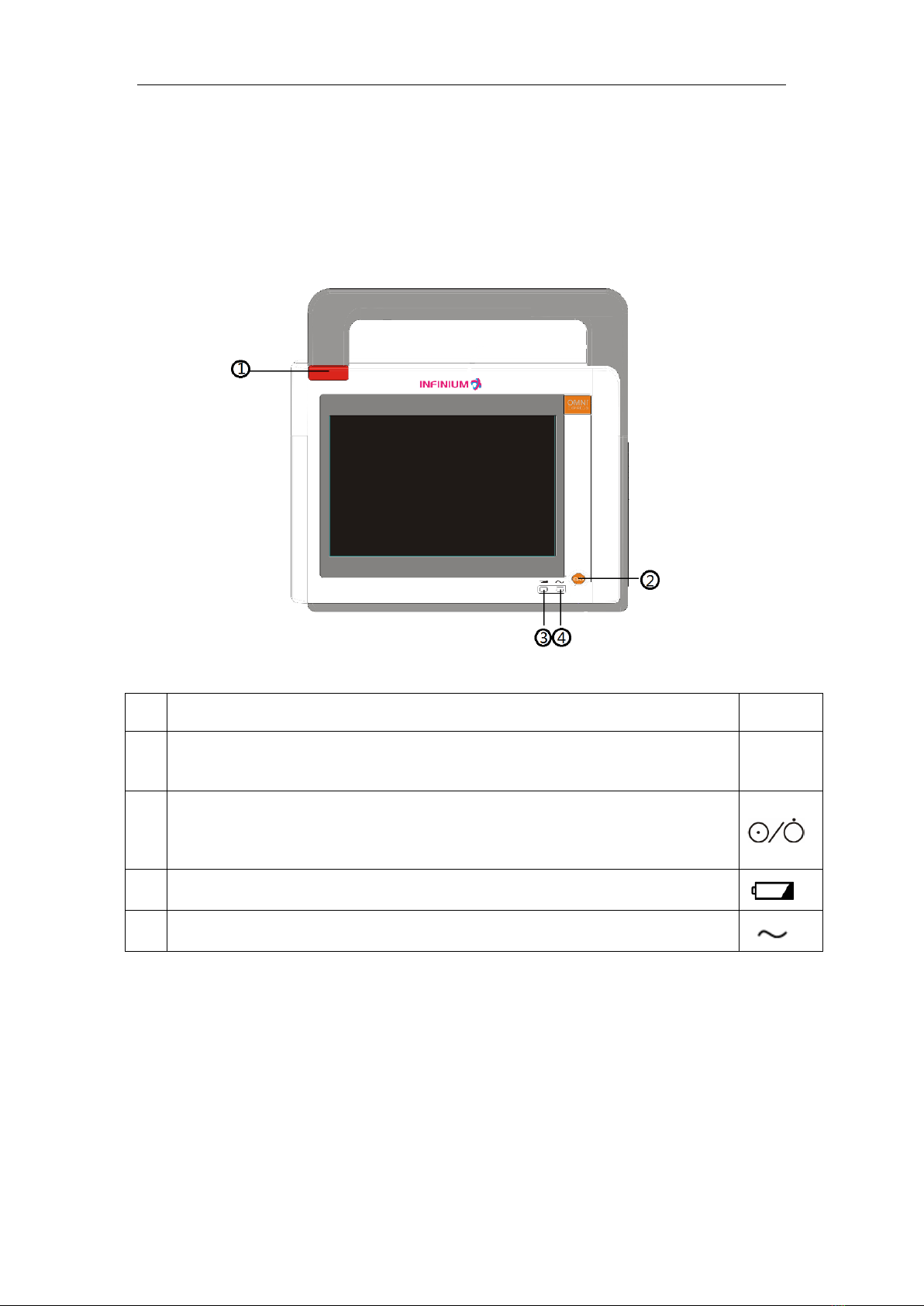
FRONT PANEL
Figure 1: Front Panel
No
.
FUNCTION
Icon
1
ALARM INDICATOR
In normal mode, no indicator lights.
In alarm mode, the alarm indicator lights up or flashes.
2 2
POWER SWITCH
This toggle switch turns the secondary power from on to off.
The monitor will continue to charge the battery as long as the AC cable is
plugged in, even if the power switch is turned off.
3 3
DC ON
This LED indicates that the monitor is powered by battery.
4 4
AC ON
This LED indicates that the monitor is plugged in toAC.
User’s Manual of OMNI Express Patient Monitor
- 6
037.007.0001 Rev.2
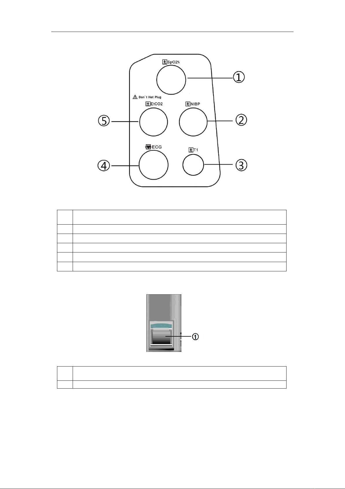
LEFT SIDE PANEL
Figure 2: Left Side Panel
No
.
FUNCTION
1
Oxygen Saturation Sensor Socket
2
NIBP Socket
3
Temperature Probe Socket
4
AAMI ECG Cable Connector
5
EtCO2/Gas /QTemp Sensor Socket (Optional)
RIGHT SIDE PANEL
Figure 3: Right Side Panel
No
.
FUNCTION
1 2
Printer (Optional)
User’s Manual of OMNI Express Patient Monitor
- 7
037.007.0001 Rev.2
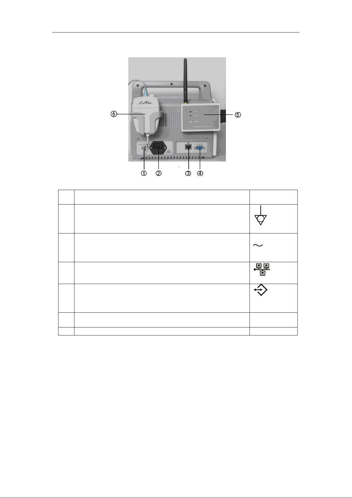
REAR PANEL
Figure 4: Rear View for Main Unit
No
.
FUNCTION
Icon
1 1
Equipotentiality Ground
Solve the ground loop and mains problem by designing
several alternate courses for electrical energy to finds its way
back to ground.
2 2
AC Input
The AC power connection is where the power cord is
connected to the monitor, the AC power fuse must be
replaced with the same type of fuse.
100-240V
50/60Hz,
150VA
3
Ethernet Interface
RJ45 interface, used to connect Central Station and Patient
Monitor. It also can be used for upgrade system.
4 3
RS-232 I/O
This digital interface connector provides serial data to most
RS-232 devices.
Used for communication interface and upgrade system
RS232
5
Wireless Transmitter
For wireless central monitor system
6
EtCO2Module (Option)

User’s Manual of OMNI Express Patient Monitor
- 8
037.007.0001 Rev.2
SYMBOLS
The following symbols may appear on the packaging, monitor or in user’s manual:
Type BF Applied Part
Defibrillation-Proof Type CF Applied Part
To identify a defibrillation-proof type CF applied part complying with
IEC 60601-1.
Note 1 - C = Cardiac
Note 2 - F = Floating Applied Part.
Rechargeable Battery
To indicates the positioning of the cells.
Manufacture’s Serial Number
Fuse Information
Date Of Manufacture
Manufacturer
Fragile
Contents of the transport package are fragile therefore it should be
handled with care.
This Way Up
Indicates correct up right position of the transport package.
Keep Away From Rain
Transport package should be kept away from rain.
Stacking Limit By Number
Maximum number of identical packages that may be stacked on one
another is eight.
General Warning, Caution, Risk Of Danger
Please read the instructions carefully before operating the product.
Stand-by
To identify the switch or switch position by means of which part of the
equipment is switched on in order to bring it into the stand-by
condition.
To signify that the instruction manual/booklet must be read
Separate collection for waste of electrical and electronic equipment. Do not
dispose of battery in municipal waste. The symbol indicates separate
collection for battery is required.

User’s Manual of OMNI Express Patient Monitor
- 9
037.007.0001 Rev.2
Indicates the temperature limits to which the medical device can be safely
exposed
Indicates the range of humidity to which the medical device can be safely
exposed
IPX1: N1=X, which means it was not required; N2=1, Protection against
vertically falling water drop
Caution: Federal law (USA) restricts this device to sale by or on the order of
a licensed healthcare practitioner.
A marking by which a manufacturer indicates that a device is in conformity
with the applicable requirements set out in this Regulation and other
applicable Union harmonization legislation providing for its affixing
User’s Manual of OMNI Express Patient Monitor
- 10
037.007.0001 Rev.2
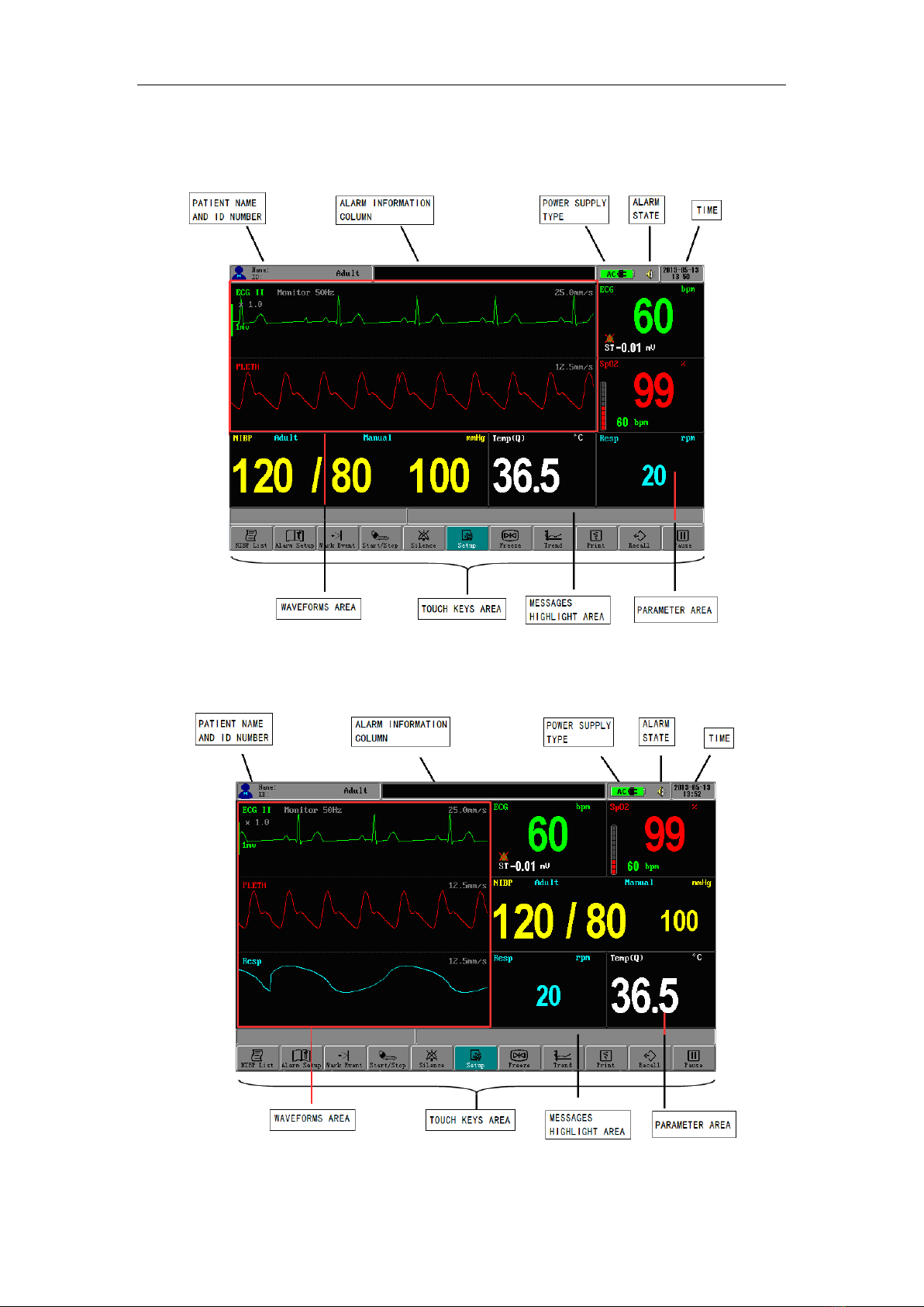
DISPLAY SCREEN PARTITION
TWO WAVEFORMS DISPLAY MODE
Figure 5: Display Screen for Two Waveforms
THREE WAVEFORMS DISPLAY MODE
Figure 6: Display Screen for Three Waveforms

User’s Manual of OMNI Express Patient Monitor
- 11
037.007.0001 Rev.2
All TFT display screen is divided into three areas:
WAVEFORM AREA
This area will display the waveforms: ECG, Pleth, Resp, EtCO2and Gas. The waveform
channel number is determined by the choice of Display Mode. Displaying waveforms are
dependent on the choice of Waveform Select.
PARAMETER AREA
This area consists of HR, Resp, SpO2, Temp, NIBP(SYS
、
DIA
、
MAP), EtCO2, Gas and so
on.
MESSAGE AREA
Time, Patient Information, Power State and some prompt information are listed here.
Assuming the main screen is being displaying, touch each menu item, it can open the
corresponding menu for setup. Access to selected item (and enter submenu if available).
Once a selection has been made, touch an appropriate selection will exit from the menu
item (or submenu) and register the current selection. If you want to exit from menu, just
touch the menu item of EXIT or OK (or CANCEL).

User’s Manual of OMNI Express Patient Monitor
- 12
037.007.0001 Rev.2
SYSTEM SETUP
System Setup includes: Factory Setup, Optional Module, Waveform Select, Printer,
Config Manager, Language, Display Mode, Alarm Suspend, Sweep Direction and etc.
Press the button of SETUP to pop up the menu below:
System Setup
Factory Setup
Optional Module
Waveform Select
Printer
Sound Level
Config Manager
Language
Demo
Display Mode
Alarm Suspend
Sweep Direction
Screen Cal
EtCO2Module
Channel 3
Channel 1
……
Alarm Print
Status
Grid Output
Waveform 2
Auto Print
Waveform 1
Waveform 3
Hospital Name
Load User Config
Save Current Config
Parameters Only
Delete User Config
Export User Config
Heart Sound
About
QTemp Module
Gas Module
Figure 7: Tree Diagram for System Setup Menu
FACTORY SEVICING SETUP
Servicing engineers use only.
1. If inputting “IP SETUP”for the password, the window for Ethernet IP address setup of
the Patient Monitor will open. It is used to connect the Patient Monitor and the Central
Station. This IP address is available only when the patient monitor is re-powered on.
2. If inputting “NUIPSET.”for the password, you can set the remote address, which
should be as same as server IP when you upgrade the program using Ethernet.
Table of contents
Other Infinium Medical Equipment manuals


