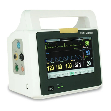
Infinium OMNI User manual

OMNI(K)
Patient Monitor
USER’S MANUAL
Ver 1.0 © 2013 Infinium Medical, Inc. All rights reserved. Issued Date: May 26th, 2013

User’s manual for OMNI (K) Portable Patient Monitor
Infinium Medical Inc.
Website: www.infiniummedical.com
Address: 12151 62nd St North #5
Largo Fl, 33773 USA
Toll Free (US call only): 866-918-8434
International: 1-727-531-8434
Fax: 1-727-531-8436

User’s manual for OMNI (K) Portable Patient Monitor
I
CONTENTS
SAFETY INFORMATION..............................................................................................................1
INTRODUCTION............................................................................................................................4
INTENDED USE......................................................................................................................4
ABOUT THIS MANUAL.........................................................................................................4
CONTROLS, INDICATORS AND SYMBOLS............................................................................5
FRONT PANEL .......................................................................................................................5
LEFT SIDE PANEL.................................................................................................................6
REAR PANEL AND RIGHT SIDE PANEL............................................................................7
SYMBOLS................................................................................................................................8
DISPLAY SCREEN PARTITION..................................................................................................9
SYSTEM SETUP..........................................................................................................................11
HOW TO MONITOR....................................................................................................................14
ALARM & SOUND........................................................................................................................15
ECG MONITORING.....................................................................................................................18
ELECTRODE INSTALLATION ...........................................................................................18
SENSOR INSTALLATION ...................................................................................................19
ECG PARAMETER SETUP ..................................................................................................19
ECG WAVEFORM SETUP ...................................................................................................21
ERROR MESSAGES OF ECG MONITORING....................................................................21
MAINTENANCE AND CLEANING ....................................................................................22
RESP MONITORING...................................................................................................................23
RESP ELECTRODE INSTALLATION.................................................................................23
RESP PARAMETER SETUP.................................................................................................24
RESP WAVEFORM SETUP..................................................................................................24
MAINTENANCE AND CLEANING ....................................................................................25
SPO2 MONITORING...................................................................................................................26
SPO2 MONITORING PRINCIPLE........................................................................................26
SPO2 SENSOR INSTALLLATION.......................................................................................26
SPO2 PARAMETER SETUP.................................................................................................27
SPO2 PARAMETER SETUP.................................................................................................27
MEASUREMENT LIMITATIONS........................................................................................27
SPO2 ERROR MESSAGES...................................................................................................28
NIBP MONITORING....................................................................................................................29
SUMMARY ON NIBP MONITORING.................................................................................29
NIBP CUFF FITTING............................................................................................................29
NIBP MONITORING INITIALIZATION.............................................................................30
NIBP SETUP ..........................................................................................................................30
MEASUREMENT LIMITATIONS........................................................................................33
NIBP ERROR MESSAGES ...................................................................................................33
MAINTAINENCE AND CLEANING...................................................................................34
TEMP MONITORING ..................................................................................................................35
THEORY OF OPERATION...................................................................................................35
TEMP SENSOR INSTALLATION........................................................................................35
TEMP PARAMETER SETUP................................................................................................35
TEMP ERROR MESSAGES..................................................................................................36
MAINTAINENCE AND CLEANING...................................................................................36

User’s manual for OMNI (K) Portable Patient Monitor
II
ETCO2 MONITORING (OPTION, Not Cleared for US Sales) ..............................................37
THEORY OF OPERATION...................................................................................................37
WARNING .............................................................................................................................37
ABBREVIATIONS AND TERMINOLOGY.........................................................................38
ZEROING THE CO2 MODULE............................................................................................38
PATIENT AND TUBING PREPARATION..........................................................................38
ETCO2 WAVEFORM SETUP...............................................................................................40
ETCO2 PARAMETER SETUP..............................................................................................40
ADVANCED SETUP.............................................................................................................42
CALIBRATION......................................................................................................................43
STATUS/ERROR MESSAGES .............................................................................................43
MAINTENANCE AND CLEANING ....................................................................................44
IBP MONITORING(OPTION).....................................................................................................45
THEORY OF OPERATION...................................................................................................45
INTRODUCTION ..................................................................................................................45
INSTRUCTIONS FOR USE OF TRANSDUCER MONITORING KIT...............................46
IBP SETUP.............................................................................................................................47
SET TRANSDUCER ZERO...................................................................................................48
IBP WAVEFORM SETUP.....................................................................................................50
PROMPT MESSAGE.............................................................................................................50
MAINTAINENCE AND CLEANING...................................................................................50
ANESTHETIC AGENT MONITORING(OPTION, PHASEIN)...........................................51
PHASEIN IRMA™ MAINSTREAM PROBE.......................................................................51
PHASEIN ISA™ SIDESTREAM ANALYZER.....................................................................57
OXYCRG DISPLAY.....................................................................................................................70
DRUG DOSE CALCULATIONS.................................................................................................71
PATIENT INFORMATION ADMINISTRATION........................................................................73
PATIENT BASIC INFORMATION SETUP.........................................................................73
TOOLS SETUP.......................................................................................................................74
NIBP LIST OBSERVATION.................................................................................................74
TREND OBSERVATION......................................................................................................75
TREND GRAPH ANALYSIS................................................................................................76
TREND TABLE ANALYSIS.................................................................................................76
ALARM EVENTS RECALL .................................................................................................77
DATA RECALL..............................................................................................................................80
DATA RECALL STORAGE..................................................................................................80
RECALL DATA DISPLAYS.................................................................................................80
RECALL OPERATION DESCRIPTIONS ............................................................................80
RECORDING(OPTION).........................................................................................................82
BATTERY OPERATION..............................................................................................................85
DISPOSAL OF DEVICE COMPONENTS ................................................................................86
PERIODIC SAFETY CHECKS...................................................................................................87
CLEANING....................................................................................................................................87
SPECIFICATIONS........................................................................................................................88
EMC................................................................................................................................................95

User’s manual for OMNI (K) Portable Patient Monitor
III
FIGURES
Figure 1: Front View for Main Unit..........................................................................................5
Figure 2: Left Side Panel for Main Unit ...................................................................................6
Figure 3: Rear View for Main Unit ...........................................................................................7
Figure 4: Display Screen Partition Diagram............................................................................9
Figure 5: Tree Diagram for Top Button ....................................................................................9
Figure 6: Tree Diagram for Bottom Button.............................................................................10
Figure 7: Tree Diagram for System Setup Menu.....................................................................11
Figure 8: Tree Diagram for ECG Setup Menu........................................................................20
Figure 9: Tree Diagram for ECG Waveform Setup Menu.......................................................21
Figure 10: Tree Diagram for Resp Setup Menu......................................................................24
Figure 11: Tree Diagram for Resp Waveform Setup Menu .....................................................24
Figure 12: Tree Diagram for SPO2 Setup Menu.....................................................................27
Figure 13: Tree diagram for SPO2 setup menu......................................................................27
Figure 14: Tree Diagram for NIBP Setup Menu.....................................................................30
Figure 15: Tree Diagram for Temp Setup Menu .....................................................................35
Figure 16: Connecting Diagram for Sample Kit.....................................................................39
Figure 17: Placing Method for the Nasal Cannula Kits.........................................................39
Figure 18: Placing Method for Oral Sampling Tip.................................................................40
Figure 19: Tree Diagram for ETCO2 Waveform Setup Menu.................................................40
Figure 20: Tree Diagram for ETCO2 Setup Menu..................................................................41
Figure 21: Tree Diagram for ETCO2 Advanced Setup...........................................................42
Figure 22: Diagram for ETCO2 Transducer Setup ................................................................47
Figure 23: Patient Mount for ETCO2 Transducer..................................................................47
Figure 24: Tree Diagram for IBP Setup Menu........................................................................48
Figure 25: Window for IBP1 or IBP2 Alarm Setup.................................................................49
Figure 26: Tree Diagram for IBP Waveform Setup Menu.......................................................50
Figure 27: Display Graph for Multi-Gas................................................................................67
Figure 28: Tree Diagram for Multi-Gas Setup Menu.............................................................68
Figure 29: Tree Diagram for Multi-Gas Wave Menu..............................................................68
Figure 30: OXYCRG Display..................................................................................................70
Figure 31: Drug Calculation Menu........................................................................................71
Figure 32: Titration table-oxytocin diagram ..........................................................................72
Figure 33: Tree Diagram for Top Button................................................................................73
Figure 34: Trend Management Menu......................................................................................75
Figure 35: Trend Graph Menu................................................................................................76
Figure 36: Windows for Alarm Event Recall ..........................................................................77
Figure 37: Last Waveform Review ..........................................................................................78
Figure 38: Recent Waveform Review ......................................................................................79
Figure 39: Prompt Window for Input Patient ID ....................................................................81
Figure 40: Printout Sample for 2 Traces ................................................................................82
Figure 41: Printout Sample for Alarm Record........................................................................83
TABLES
Table 1: Description for controls on front panel of OMNI (K).................................................5
Table 2: Description for controls on side panel of OMNI (K) ..................................................6
Table 3: Description for controls on rear and side panel of OMNI (K)....................................7
Table 4: Description for Symbols..............................................................................................8
Table 5: SPO2 Error Messages...............................................................................................28
Table 6: NIBP Error Messages ...............................................................................................33
Table 7: Staus/Error Messages for ETCO2.............................................................................43
Table 8: Limits for Waveform Scale for IBP............................................................................49
Table 9: Prompt Message for IBP Measure............................................................................50
Table 10: NIBP List.................................................................................................................74
Table 11: Trend Table..............................................................................................................77
Table 12: Printout Sample for Trend Table.............................................................................82
This manual suits for next models
1
Table of contents
Other Infinium Medical Equipment manuals
Popular Medical Equipment manuals by other brands

Getinge
Getinge Arjohuntleigh Nimbus 3 Professional Instructions for use

Mettler Electronics
Mettler Electronics Sonicator 730 Maintenance manual

Pressalit Care
Pressalit Care R1100 Mounting instruction

Denas MS
Denas MS DENAS-T operating manual

bort medical
bort medical ActiveColor quick guide

AccuVein
AccuVein AV400 user manual
