Infinium CLEO User manual

CLEO
Patient Monitor
USER’S MANUAL
Ver 1.2 © 2014 Infinium Medical Inc. All rights reserved.
Issued Date: November 20, 2014

User’s manual of CLEO Patient Monitor
Infinium Medical Inc.
Website: www.infiniummedical.com
Address: 12151 62nd St North #5
Largo Fl, 33773 USA
Toll Free (US call only): 866-918-8434
International: 1-727-531-8434
Fax: 1-727-531-8436
To obtain information about a warranty, if any, for this product, contact Infinium Medical Inc,
Technical Services or your local Infinium Medical, Inc. representative.
Nellcor is a trademark of NELLCOR OXIMAX

User’s manual of CLEO Patient Monitor
- 1 -
CONTENTS
SAFETY INFORMATION.....................................................................................................4
INTRODUCTION .................................................................................................................7
INTENDED USE......................................................................................................................7
ABOUT THIS MANUAL.........................................................................................................7
CONTROLS, INDICATORS,AND SYMBOLS.....................................................................8
FRONT AND SIDE PANEL.....................................................................................................8
REAR PANEL ..........................................................................................................................9
SYMBOLS..............................................................................................................................10
DISPLAY SCREEN PARTITION........................................................................................11
SINGLE SPO2 DISPLAY.......................................................................................................12
SINGLE ETCO2 DISPLAY....................................................................................................12
SPO2+ETCO2 DISPLAY.......................................................................................................13
SPO2+NBP DISPLAY............................................................................................................13
SPO2 +NBP+ETCO2 DISPLAY............................................................................................14
SPO2+NBP DISPLAY............................................................................................................14
SYSTEM SETUP...............................................................................................................15
FACTORY SEVICING SETUP..............................................................................................15
SOUND VOLUME.................................................................................................................16
ALARM SWITCH..................................................................................................................16
MODULE SELECT................................................................................................................16
DEFAULT CONFIG ...............................................................................................................16
SAVE CONFIG.......................................................................................................................16
HOW TO MONITOR ..........................................................................................................17
ALARM & SOUND.............................................................................................................18
ALARM..................................................................................................................................18
SOUND...................................................................................................................................19
SPO2 MONITORING.........................................................................................................20
SPO2 MONITORING PRINCIPLE........................................................................................20
SPO2 SENSOR INSTALLLATION .......................................................................................20
SPO2 WAVEFORM SETUP...................................................................................................20
SPO2 PARAMETER SETUP .................................................................................................21
MEASUREMENT LIMITATIONS ........................................................................................22
SPO2 ERROR MESSAGES...................................................................................................22
NELLCOR INFORMATION..................................................................................................24
NIBP MONITORING..........................................................................................................25
SUMMARY ON NIBP MONITORING.................................................................................25
NIBP CUFF FITTING ............................................................................................................25

User’s manual of CLEO Patient Monitor
- 2 -
NIBP MONITORING INITIALIZATION..............................................................................26
NIBP PARAMETER SETUP..................................................................................................26
NIBP LIST OBSERVATION...................................................................................................28
MEASUREMENT LIMITATIONS ........................................................................................29
NIBP ERROR MESSAGES....................................................................................................30
MAINTAINENCEAND CLEANING....................................................................................30
ETCO2 MONITORING.......................................................................................................31
THEORY OF OPERATION....................................................................................................31
WARNINGS, CAUTIONS AND NOTES ..............................................................................31
ABBREVIATIONSAND TERMINOLOGY .........................................................................32
ZEROING THE CO2 MODULE............................................................................................32
PATIENTAND TUBING PREPARATION............................................................................33
ETCO2 WAVEFORM SETUP................................................................................................34
ETCO2 PARAMETER SETUP ..............................................................................................35
ADVANCED SETUP..............................................................................................................36
CALIBRATION......................................................................................................................37
STATUS/ERROR MESSAGES..............................................................................................38
MAINTENANCE AND CLEANING.....................................................................................38
RECALL DATA...................................................................................................................39
PATIENT BASIC INFORMATION SETUP...........................................................................39
CLOCK SETUP......................................................................................................................40
HOW TO RECALL ................................................................................................................40
BATTERY OPERATION.....................................................................................................43
BATTERY RECYCLE............................................................................................................43
DISPOSAL OF DEVICE COMPONENTS .........................................................................44
CLEANING.........................................................................................................................45
PERIODIC SAFETY CHECKS ..........................................................................................45
SPECIFICATIONS.............................................................................................................46
EMC ...................................................................................................................................49
ELECTROMAGNETIC IMMUNITY....................................................................................49

User’s manual of CLEO Patient Monitor
- 3 -
FIGURES
Figure 1: Front and Side Panel....................................................................................8
Figure 2: Rear View for Main Unit................................................................................9
Figure 3: Single SpO2Display Screen.......................................................................12
Figure 4: Single EtCO2Display Screen.....................................................................12
Figure 5: SpO2 and EtCO2Display Screen................................................................13
Figure 6: SpO2 and NBP Display Screen...................................................................13
Figure 7: SpO2, EtCO2and NBP Display Screen......................................................14
Figure 9: Tree Diagram for System Setup Menu .......................................................15
Figure 10: Window for Ethernet IPAddress Setup ....................................................15
Figure 11: Tree Diagram for Pleth Menu....................................................................20
Figure 12: Tree Diagram for SpO2Setup Menu.........................................................21
Figure 13: Tree Diagram for NIBP Setup Menu.........................................................26
Figure 14: Window for NIBP List Observation............................................................29
Figure 15: Temperature Site and PatientAge.............Error! Bookmark not defined.
Figure 17: Tree Diagram for EtCO2Waveform Setup Menu .....................................35
Figure 18: Tree Diagram for EtCO2Parameter Setup Menu.....................................35
Figure 19: Tree Diagram for EtCO2Advanced Setup................................................37
Figure 20: Tree Diagram for Patient Setup................................................................39
Figure 21: Tree Diagram for Clock Setup...................................................................40
Figure 22: User Choose and Module Choose............................................................40
Figure 23: Tabular Trend for SpO2.............................................................................41
Figure 24: Tabular Trend for EtCO2...........................................................................41
Figure 25: Tabular Trend for NBP...............................................................................42

User’s manual of CLEO Patient Monitor
- 4 -
SAFETY INFORMATION
This section contains important safety information related to general use of the CLEO
Patient Monitor. Other important safety information appears throughout the manual in
sections that relate specifically to the precautionary information. Read all text surrounding
all precautionary information.
The CLEO can be powered by an internal battery that provides 3 hours of monitoring from
fully charged batteries. The batteries are continuously recharged when AC power is
connected to the monitor.
A warning message appears on the screen and an audible alarm sounds when the
remaining battery power is only enough for 15 minutes of operation. The user should
connect the monitor to an external power source to avoid loss of patient monitoring action.
External power sources may be connected, disconnected, and reconnected without
interrupting the monitoring action.
[WARNING]: CLEO Patient Monitor should not be used as an apnea monitor.
[WARNING]: MRI Unsafe – DO NOT use in MRI environments.
[WARNING]: CLEO Patient Monitor may not operate effectively on patients who are
experiencing convulsions or tremors.
[WARNING]: DO NOT lift the monitor by the sensor cable, blood pressure hose, or
power cord because the cable, lead, or cord could disconnect from the monitor,
causing the monitor to drop on the patient.
[WARNING]: Explosion hazard. DO NOT use the CLEO in the presence of flammable
anesthetics or other flammable substance in combination with air, oxygen-enriched
environments, or nitrous oxide.
[WARNING]: CLEO Patient Monitor is defibrillator proof. It may remain attached to the
patient during defibrillation or while an electrosurgical unit is in use, but the readings
may be inaccurate during use and shortly thereafter.
[WARNING]: CLEO Patient Monitor should only be used onAdult Patients.
[NOTE]: Before use, please read this manual carefully.
WARNING: CLEO patient monitor is a prescription device and is to be operated by
qualified personnel only.
CAUTION: Federal law (USA) restricts this device to sale by or on the order of a
physician only.

User’s manual of CLEO Patient Monitor
- 5 -
[WARNING]:The CLEO monitor is not intended to be used with Xenon or Helium
gasses
[WARNING]:If there is any doubt about the integrity of the protective earth conductor
arrangement, operate the monitor on internal battery power until the AC power supply
protective conductor is fully functional.
[WARNING]: To prevent electrical hazards to all personnel, CLEO Patient Monitor
must be properly grounded. The chassis grounding assembly, Universal Switching
Power Supply, and the power cord supplied with the equipment provides for this
protection. DO NOT attempt to defeat this protection by modifying the cords or using
ungrounded adapters.
DO NOT remove the monitor cover except to replace the
battery.
[WARNING]: DO NOT use the CLEO to monitor patients who are linked to heart/lung
machines.
[WARNING]: DO NOT touch, press, or rub the display panels with abrasive cleaning
compounds, instruments, brushes, rough surface materials, or bring them into contact
with anything that could scratch the panel.
[WARNING]: DO NOT autoclave, ethylene oxide sterilize, or immerse these monitors
in liquid. Use the cleaning solution sparingly. Excessive solution can flow into the
monitor and cause damage to internal components. Do not use petroleum-based or
acetone solutions, or other harsh solvents, to clean the monitor. These substances
attack the monitor’s materials and device failure can result. Unplug the monitors
before cleaning or disinfecting.
[WARNING]: Enclosure leakage current is less than 100 microamperes (µA);
however, always consider additional leakage current that can be caused by other
equipment used on the patient at the same time as these monitors.
[WARNING]: To ensure patient safety, DO NOT places the monitor in any position that
might cause it to fall on the patient.
[WARNING]: The user must check the equipment prior to use and ensure its safe and
proper use.
[WARNING]: To ensure that the leakage current protection remains within the
specifications, use only the patient cables supplied with or specifically intended for use
with the CLEO Monitors. Carefully route patient cables to reduce the possibility of
patient entanglement or strangulation.
[WARNING]: Disconnect the CLEO and sensors during magnetic resonance imaging
(MRI) scanning. Use during MRI could cause burns or adversely affect the MRI image
or the monitor’s accuracy. Also, to avoid burns, remove the sensors from the patient
before conducting MRI.

User’s manual of CLEO Patient Monitor
- 6 -
Caution: When connecting the CLEO to any instrument, verify proper operation before
clinical use. Both the CLEO and the instrument connected to it must be connected to a
grounded outlet.Accessory equipments connected to this patient monitor must be certified
according to the respective IEC standards (e.g. IEC 60950 for information technology
equipment and IEC 60601-1 for medical electrical equipment). Furthermore all
configurations shall comply with the valid version of the system standard IEC 60601-1-1.
Any person who connects additional equipment to the signal input or signal output is
responsible to ensure the system complies with the requirements of the valid version of
the system standard IEC 60601-1-1. If you have any questions, please be free to contact
our company or customer service.
To ensure accurate readings, consider the environmental conditions that are present and
the condition of the patient. See the appropriate sections of the manual for specific safety
information related to these conditions.

User’s manual of CLEO Patient Monitor
- 7 -
INTRODUCTION
INTENDED USE
ABOUT THIS MANUAL
INTENDED USE
The purpose and function of the CLEO patient monitor is to monitor basic physiological
parameters including
•NIBP(systolic and diastolic)
•SpO2
•ETCO2
The target population is for adults only
It may be used as bedside or portable monitor and be used in all hospitals and
hospital-type facilities such as clinics and emergency room facilities. It is to be used under
the direct supervision of a licensed healthcare practitioner.
ABOUT THIS MANUAL
This manual explains how to set up and use the CLEO Patient Monitor. Important safety
information relating to general use of the CLEO appears before this introduction. Other
important safety information is located throughout the text where applicable. Read the
entire manual including the Safety Information section before you operate the
monitor.
[WARNING]: CLEO Patient Monitor is intended only as an adjunct in patient
assessment. It must be used in conjunction with clinical signs and symptoms.
User’s manual of CLEO Patient Monitor
- 8 -
CONTROLS, INDICATORS, AND SYMBOLS
FRONT AND SIDE PANEL
REAR PANEL
SYMBOLS
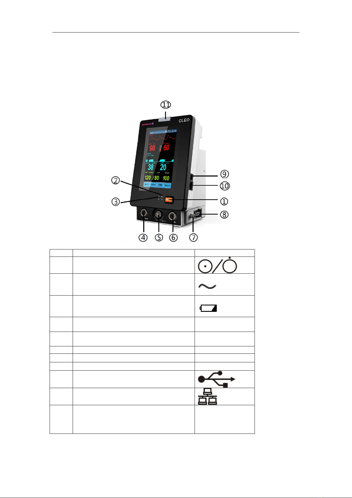
FRONT AND SIDE PANEL
Figure 1: Front and Side Panel
No.
Function
Icon
1.
Power Switch
2.
AC ON
This LED indicates that the monitor is
powered byAC.
3.
DC ON
This LED indic
ates that the monitor is
powered by battery.
4.
NIBP Port for the connection with the
blood pressure cuff hose
5.
Oxygen Saturation Sensor Port for
Infinium SpO2
6.
Sensor Port for External EtCO2
7.
Air Pipe for Inner EtCO
2
8.
Oxygen Saturation Sensor Port for Nellcor
9.
USB Port
Transfer data to PC; Upgrade program
10.
Ethernet Port
Upgrade program
11.
Alarm Indicator
In normal mode, no indicator lights.
In alarm mode, the alarm indicator
flashes.

User’s manual of CLEO Patient Monitor
- 9 -
REAR PANEL
Figure 2: Rear View for Main Unit
No.
Function
Icon
1
BatteryAccess
2
AC Input and Fuse
The AC power connection is where facility
line power is connected to this monitor,
the AC power fuses must be replaced with
the same type and rating fuse.
100/240
V~
50/60Hz, 30VA,
F2AL 250V
3
Equipotential Grounding
Solve the ground loop and mains problem
by designing several alternate courses for
electrical energy to finds its way back to
ground.

User’s manual of CLEO Patient Monitor
- 10 -
SYMBOLS
The following symbols may appear on the packaging, monitor or in user’s manual:
Type BF Applied Part
Manufacture’s Serial Number
Fuse Information
Date of Manufacture
Manufacturer
Fragile
Contents of the transport package are fragile therefore it shall be
handled with care.
This Way Up
Indicates correct up right position of the transport package.
Keep Away From Rain
Transport package shall be kept away from rain.
Stacking Limit By Number
Maximum number of identical packages which may be stacked on
one another is eight.
General Warning, Caution, Risk Of Danger
Please read the instructions carefully before operating the product.
Stand-by
To identify the switch or switch position by means of which part of the
equipment is switched on in order to bring it into the stand-by
condition.
Prescription Only
To be sold by or on the order of a physician only.
User’s manual of CLEO Patient Monitor
- 11 -
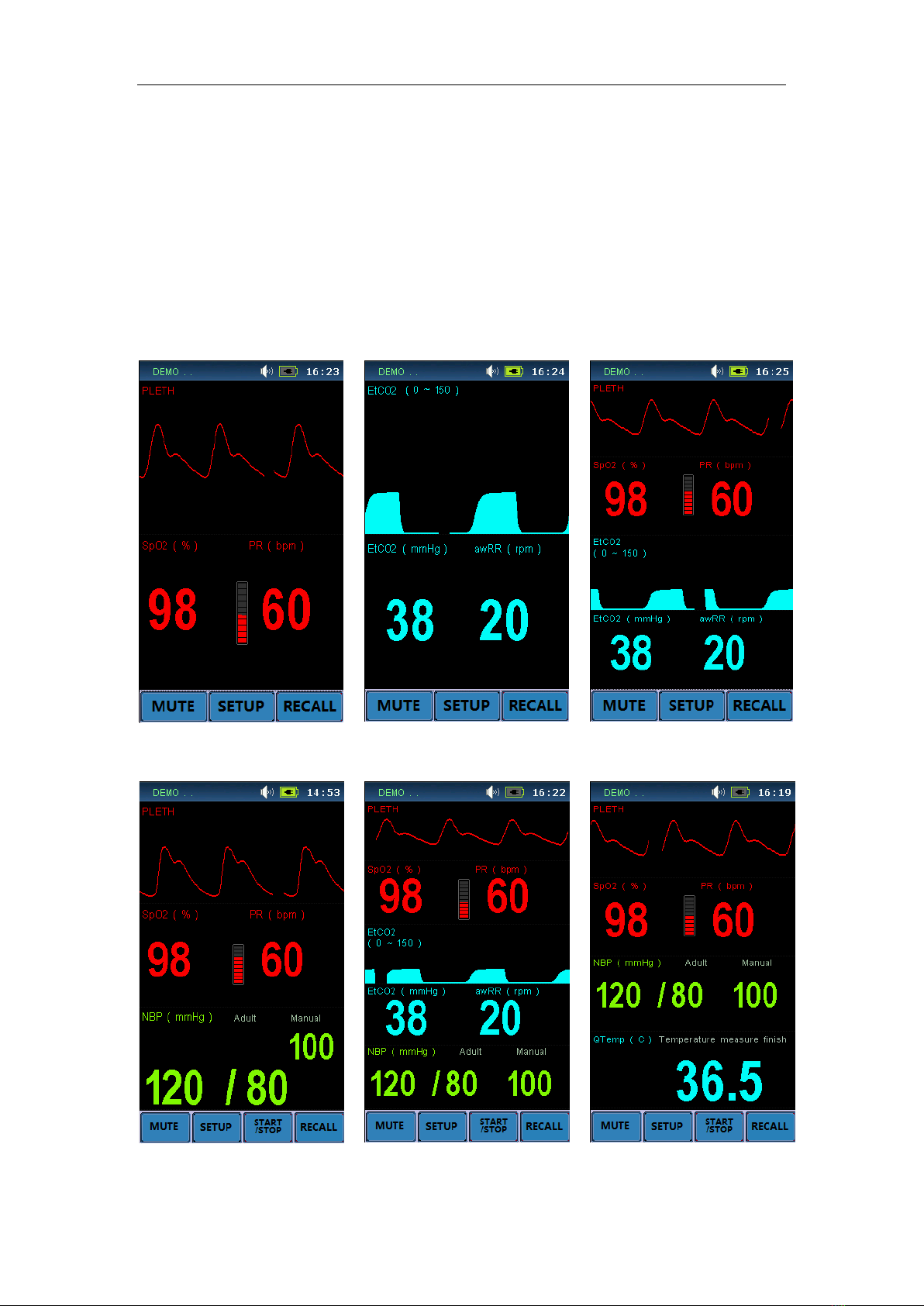
DISPLAY SCREEN PARTITION
There are six groups for module combination in all. The user can choose what to measure
as required in Module Select Menu.
The combination is as below:
SpO2
EtCO2
SpO2 + EtCO2
SpO2 + NBP
SpO2+ NBP + EtCO2
SpO2+ NBP
The display interface is as below:
①Single SpO2②Single EtCO2③SpO2 + EtCO2
④SpO2 + NBP ⑤SpO2 + NBP + EtCO2⑥SpO2 + NBP
User’s manual of CLEO Patient Monitor
- 12 -
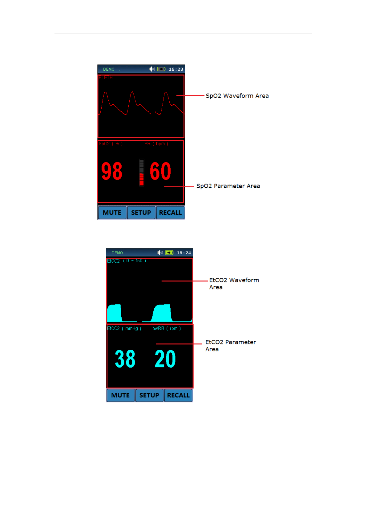
SINGLE SPO2 DISPLAY
Figure 3: Single SpO2Display Screen
SINGLE ETCO2 DISPLAY
Figure 4: Single EtCO2Display Screen

User’s manual of CLEO Patient Monitor
- 13 -
SPO2+ETCO2 DISPLAY
Figure 5: SpO2 and EtCO2Display Screen
SPO2+NBP DISPLAY
Figure 6: SpO2 and NBP Display Screen

User’s manual of CLEO Patient Monitor
- 14 -
SPO2 +NBP+ETCO2 DISPLAY
Figure 7: SpO2, EtCO2and NBP Display Screen
SPO2+NBP DISPLAY
Figure 8: SpO2, NBP and Display Screen

User’s manual of CLEO Patient Monitor
- 15 -
SYSTEM SETUP
System Setup includes: Factory Setup, Demo Switch, Sound Volume, Alarm Switch,
Module Select, Default Config, Save Config and etc.
Press the button of SETUP to pop the System Setup menu, the tree diagram is as
below:
System Setup
Factory Setup
Alarm Switch
Default Config
Save Config
Module Select
SpO
2
Module
Demo Switch
Sound Volume
Upgrade Setup NBP Module
EtCO
2
Module
Figure 9: Tree Diagram for System Setup Menu
FACTORY SEVICING SETUP
Servicing engineer use only.
1. If input IPSETUP for the password, the “Upgrade Setup” menu item would be
replaced by “IP Address Setup” menu item. And then enter the IP Setup submenu,
Patient Monitor will pop out as following:
Figure 10: Window for Ethernet IPAddress Setup
If click OK item, the Ethernet IP address setup of the Patient Monitor is set and saved.
This IP address is available only when the patient monitor is re-powered on.
2. If input DEMO… for the password and then open the Demo Switch, you will see the

User’s manual of CLEO Patient Monitor
- 16 -
simulation measurement.
The Demo mode is for demonstration purpose only. To avoid that the simulated data
are mistaken for the monitored patient’s data, you must not change into demo mode
during monitoring, otherwise, improper patient monitoring and delayed treatment
could result.
This function is for servicing engineer only.
3. If input UPGRADE for the password, the Upgrade Setup Menu will be enable.
This function is for servicing engineer only.
SOUND VOLUME
Mainly use to adjust the sound to four levels, separately they are: I, II, III, IV. Also it can be
set to OFF.
ALARM SWITCH
It could be choose ON or OFF. When it is ON, the alarm is enabled, and then you should
set the each parameter’s alarm switch in the Parameter Setup. When it is OFF, the alarm
is disabled which means all alarm is closed.
MODULE SELECT
Choose what module is to open as you want.
DEFAULT CONFIG
If the parameter settings are confused on irrational, you can call the Default Config to
recover original state. The screen will display a menu to let you confirm the setup.
After return to the above confirmation menu, a message of “Load Successfully!” will
display in the message highlight area, showing that the system has begun to work with
the new settings.
SAVE CONFIG
You can change monitor settings as required and then save the changed settings. The
screen will display a menu to let you confirm the setup:
After return to the above confirmation menu, a message of “Save successfully” will display
in the message highlight area, showing that the system and all monitoring parameter
settings have been saved (see each chapter).
[NOTE]
Make sure that the changes are suitable for your patient.

User’s manual of CLEO Patient Monitor
- 17 -
HOW TO MONITOR
1. According to the parameter needed, connect the correlated sensors to the sockets at
the bottom of the panel;
2. Connect with the power supply, press the power switch in the front panel;
3. Power indicator is bright, the display screen enter the main screen after 10 seconds;
4. Connect the detector with the patient;
5. Set monitoring parameters (see chapters below) ;
6. Enter the monitoring state.
[CAUTION]:Follow local government ordinances and recycle instructions regarding
disposal or recycling of device components, including batteries.
[CAUTION]:If the CLEO is to be stored for a period of 2 months or longer, notify service
personnel to remove the battery from the monitor prior to storage. Recharge the battery
when the battery has not been recharged for 2 or more months.

User’s manual of CLEO Patient Monitor
- 18 -
ALARM & SOUND
ALARM
When the monitor detects certain conditions that require user attention, the CLEO Patient
Monitor enters an alarm state. The monitor response is indicated by:
• Visual alarm indicators
• Audible alarm indicators
ALARM PRIORITY
The monitor’s visual and audible responses to a detected alarm depend on the priority of
the alarm; High, Medium, or Low.
A higher priority alarm will supersede a lower priority alarm.
The three categories of alarms are summarized in the following paragraphs.
High Priority
Indicating that immediate OPERATOR response is required:
No breath (4 seconds have passed with no breath from EtCO2)
Medium Priority
Indicating that prompt OPERATOR response is required:
High/Low numeric value limits violated (such as High/Low SpO2limits violated,
High/Low Sys./Dia. blood pressure limits violated, High/Low Temperature limits
violated, etc.).
Low Priority
Indicating that OPERATOR awareness is required:
Module communicates error (such as SpO2com error).
Sensor off (Such as SpO2sensor disconnect, temperature probe disconnect, etc.)
VISUAL ALARM INDICATORS
When an alarm occurs, the CLEO responds with visual alarm indications. The flashing
rates for the three categories of alarms are shown. The CLEO uses flashing colors to
indicate high and medium priority alarm as following Flashing Rates.
Alarm Category
Flashing Rate
High Priority
Two flashes in 1 second
Medium priority
One flash in 2 seconds
Low priority
Constant (on) (non-flashing)
When a low priority alarm occurs, a non-flashing alarm message appears in the
message area. If more than one low priority alarm is present, the alarm messages
“rotate”. On the CLEO the alarm led color will change to a solid yellow for a low priority
alarm
A medium priority alarm is activated when a parameter is outside its alarm limits, the
out-of-limit numeric value and the bell icon in the corresponding Numeric Frame flash
at the medium priority rate. Only the numeric frame background color will flash yellow
for a medium priority alarm in the CLEO.
When the high-priority No breath alarm occurs, the alarm led color will flash red. A
non-flashing No breath message appears in the message area and will override any
other messages which may be present (there is no message “rotation” in this
instance).
Other manuals for CLEO
1
Table of contents
Other Infinium Medical Equipment manuals


Popular Medical Equipment manuals by other brands


Getinge
Getinge Arjohuntleigh Nimbus 3 Professional Instructions for use

Mettler Electronics
Mettler Electronics Sonicator 730 Maintenance manual

Pressalit Care
Pressalit Care R1100 Mounting instruction

Denas MS
Denas MS DENAS-T operating manual

bort medical
bort medical ActiveColor quick guide

AccuVein
AccuVein AV400 user manual


