the display screen as described below.
Long press the power button for 5s to start the
system. When the system is working, long
press for 3s to display the shutdown menu,
and long press 10s to force shutdown. Settings
are saved after shutdown.
Rotary operation and button operation can be
performed for the encoder. Tap the rotary
encoder to enter the menu interface. Rotate
the encoder knob forward or backward to
switch menu options (rotate the encoder
clockwise and the cursor will go down), and
click to select the menu options. In the display
interface, you can zoom in or zoom out by
rotating the encoder, the default value is 1 ×,
the zoom range is 1 × to 4×, and the zoom
information can not be saved after power off.
During zooming, the infrared image will be
zoomed around the center spot of the reticle,
and the size of the reticle will be changed
accordingly.
6.1Power-On
6.3 Operation Interface
6.2 Button Functions
Figure 5 Startup Picture Caution: it is not allowed to press the
encoder during rotating.
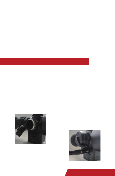
After the battery is installed and can supply
power normally, long press the power
button for 5 seconds to get the thermal
imager started. When the system is started,
it will display the image and booting up
information (product model), as shown in
Figure 5.
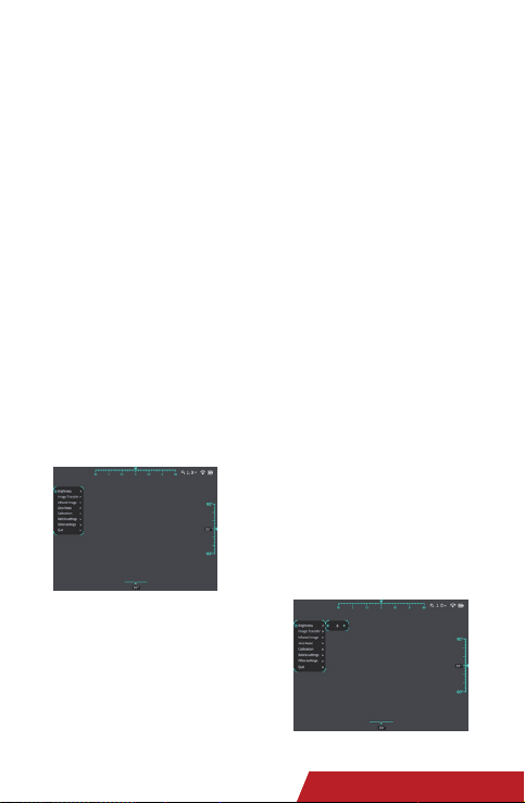
6.3.1 Entering Operation Interface
The initial screen shows information
about nine axes. The azimuth is shown in
the upper center (the cursor moves in
east, west, south, and north directions,
without showing the angle value); the
role angle is shown in the lower center
(range: ±90°); the pitch angle is shown
When the screen shows real time image
and the startup picture disappears, the
system is successfully started. Background
calibration will be performed after booting
up. Please do not open the objective lens
cover before the background calibration
(in case of misoperation, close the lens
cover and then short press the power
button for manual background calibration).
Functions and parameters can be set through
6 Operation Instructions on the right (range: ±90°). Respectively,
the cursors in the top right-hand corner
are the digital zoom ratio (on the main
interface, turn the encoder clockwise
unidirectionally to zoom the image in
1-2-3-4× increments, with the real-time
zoom ratio shown in the top right-hand
corner; in 4× mode, turning the encoder
clockwise does not zoom the image but
turning anticlockwise can zoom the image
in 4-3-2-1× decrements; similarly, in 1×
mode, turning the encoder anticlockwise
does not zoom the image), wireless
output (you can select image transmission
mode on the system's main menu, as
required), and battery level (detected by
the system and shown in real time; when
the battery is about to use up, the battery
level box turns red; the thermal imager is
automatically powered off if the battery is
not sufficient for its operation, after a
countdown prompt.)
Press and turn the encoder to enter the
main menu, as shown in Figure 6.
5Tyke-L3
Operation and Maintenance Manual