Ingecon SUN 125 U 208 Outdoor User manual

INGECON SUN Power U
Outdoor
Installation manual

ABB2000IKI01_B
05/2013
Ingeteam Inc
3550 W. Canal St.
Milwaukee, WI 53208 - USA
Tel.: +1 (414) 934 4100
Fax.: +1 (414) 342 0736
e-mail: solar.us@ingeteam.com
Service Call Center: +1 (414) 934 4158
The copy, distribution or use of this document or of its content requires written authorisation. Any breach thereof will
be reported for damages. All rights reserved including those of patent rights or design registration.
The conformity of the document content with the hardware described has been checked. However, discrepancies may
exist. Liability will not be assumed for total concordance. The information contained in this document is regularly
reviewed and it is possible that there may be changes in subsequent editions. Other functions may be available which
are not covered by this document.
This document may be changed.

ABB2000IKI01 iii
Installation manual Ingeteam
Important safety precautions
This manual contains important instructions for the installation, handling and use of the following models:
Units with a transformer
INGECON SUN 125 U 208 Outdoor
INGECON SUN 125 U 480 Outdoor
Units without a transformer
INGECON SUN 125 TL U 208 Outdoor
INGECON SUN 165 TL U 275 Outdoor
INGECON SUN 200 TL U 330 Outdoor
INGECON SUN 220 TL U 360 Outdoor
Read these instructions and keep them in a safe place.
General warnings
The operations described in the manual may be performed only by qualified personnel.
The status of qualified personnel referred to in this manual will be, as a minimum, that which meets
all the standards, regulations and laws regarding safety applicable to the tasks of installing and oper-
ating this unit.
The responsibility for designating qualified personnel will always fall to the company to which the
personnel belong. It is necessary to decide which workers are suitable or not for carrying out specific
work to preserve their safety at the same time as complying with occupational safety legislation.
These companies are responsible for providing appropriate training in electrical equipment to their
personnel and for familiarizing them with the contents of this manual.
All applicable safety-related legislation for electrical work must be complied with. Danger of electric
shock.
Compliance with the safety instructions set out in this manual or in the suggested legislation does
not imply exemption from other specific standards for the installation, place, country or other circum-
stances that affect the inverter.
Opening the door of the housing does not imply there is no voltage inside.
The risk of electric shock exists even after disconnecting from the grid, the PV array and the auxiliary
supply.
Only qualified personnel may open it, following the instructions in this manual.
The entire manual must be read and understood in full prior to manipulating, installing or operating
the unit.
Category III - 1000-Volt measuring instruments must be used for checking for the absence of voltage.
Ingeteam accepts no liability for any damages caused by improper use of the equipment.

ABB2000IKI01
iv
Installation manual
Ingeteam
Carry out all control and handling without voltage.
As a minimum security measure in this operation, the so-called five golden rules should always be
followed:
1. Disconnect
2. Prevent any possible resupply
3. Check there is no voltage
4. Ground and short circuit the equipment
5. Protect from live elements, if any, and put up safety signs around the work zone.
Until these five steps are completed, the work area cannot be considered voltage-free and any work
performed will be considered to be work on live equipment.
Potential hazards for people
Bear in mind the following warnings concerning personal safety.
DANGER: Electric shock.
The equipment may remain charged after disconnecting the PV array, mains power and auxiliary
power.
Carefully follow the mandatory steps in the manual for removing the voltage.
DANGER: Explosion.
There is a very low risk of explosion in very specific cases of malfunction.
The casing will protect people and property from the explosion only if it is correctly closed.
DANGER: Crushing and joint injuries.
Always follow the indications in the manual on moving and placing the unit.
The weight of this unit can cause lesions, serious injury and even death if not handled correctly.
DANGER: High temperature.
The flow of outlet air can reach high temperatures which can cause injury to anybody exposed to it.

ABB2000IKI01 v
Installation manual Ingeteam
Potential hazards for the equipment
Bear in mind the following warnings concerning protection of the equipment.
CAUTION: Ventilation.
The unit requires quality air flow while it is operating.
Keeping the unit in the upright position and the inlets free of obstacles is essential for this air flow
to reach the inside.
CAUTION: Connections.
After all duly authorized handling, check that the equipment is ready to start operation. Only after this
can it be connected following the instructions in the manual.
Do not touch boards or electronic components. The most sensitive components can be damaged or
destroyed by static electricity.
Do not disconnect or connect any terminal while the unit is operating. Disconnect and check for
absence of voltage first.
Personal protection equipment (PPE)
Use all items comprising the protection equipment.
Chapter “4. Safety instructions” contains references to the use of this equipment depending on the situation.
The standard personal protective equipment is:
• Safety goggles for mechanical hazards
• Safety goggles for electrical hazards
• Safety footwear
• Helmet

ABB2000IKI01
vi
Installation manual
Ingeteam
Cabling and torque requirements
Connection to the PV array must be with the following minimum types of cable; the maximum for input terminals is
DC 250 kcmil (0.2 in2, 127 mm2) and for output terminals AC 300 kcmil (0.24 in2, 152 mm2):
Models Wiring Material Section
Tightening torque
St.st. bolts
(unlubricated)
13/12”
(M10)
31/64”
(M12)
Input terminals (DC)
All models
8 cables per polarity 4 AWG 194 °F (90 °C) Copper
41.7 kcmil
(0.03 in2,
21.2 mm2)
385 lb.in
(43.5 Nm)
650 lb.in
(73.4 Nm)
2 AWG 194 °F (90 °C) Aluminium
66.4 kcmil
(0.05 in2,
33.6 mm2)
385 lb.in
(43.5 Nm)
650 lb.in
(73.4 Nm)
All models
4 cables per polarity 2/0 AWG 194 °F (90 °C) Copper
133 kcmil
(0.1 in2,
67.4 mm2)
385 lb.in
(43.5 Nm)
650 lb.in
(73.4 Nm)
4/0 AWG 194 °F (90 °C) Aluminium
212 kcmil
(0.17 in2,
107 mm2)
-650 lb.in
(73.4 Nm)
Output values (AC)
125 U 208, 125 TL U 208,
165 TL U 275, 200 TL U 330
220 TL U 360
2 cables per phase
250 kcmil 194 °F (90 °C) Copper
250 kcmil
(0.2 in2,
127 mm2)
-650 lb.in
(73.4 Nm)
300 kcmil 194 °F (90 °C) Aluminium
300 kcmil
(0.24 in2,
152 mm2)
-650 lb.in
(73.4 Nm)
125 U 480
2 cables per phase 2 AWG 194 °F (90 °C) Copper
66.4 kcmil
(0.05 in2,
33.6 mm2)
385 lb.in
(43.5 Nm)
650 lb.in
(73.4 Nm)
1/0 AWG 194 °F (90 °C) Aluminium
106 kcmil
(0.08 in2,
53.5 mm2)
385 lb.in
(43.5 Nm)
650 lb.in
(73.4 Nm)
In order to keep the nuts and bolts of the equipment in a proper condition, it is important while tight-
ening them to make sure there is no dirt or shavings on the threads and to apply a suitable lubricant.
Cabling must comply with the following codes:
• National Electrical Code ANSI/NFPA.
• Canadian Electrical Code CEC.
• Other local or state codes if applicable.
Ingeteam recommends the use of 31/64” (M12) terminals.
Inverter installation
The inverter must always be installed in accordance with the relevant requirements of the NEC (National Electrical
Code ANSI/NFPA), CEC (Canadian Electrical Code), and other applicable codes, including those relating to circuits
and equipment operating at over 600 V.

ABB2000IKI01 vii
Installation manual Ingeteam
Spares
Units with a transformer
Reference Quantity INGECON SUN 125 U 208 Outdoor INGECON SUN 125 U 480 Outdoor
U1 1 INGECON SUN 208 V 3 ph electronics block INGECON SUN 480 V 3 ph electronics block
R1, R2, R3 3 Tubular silicon power resistor 200 W
C1, C2, C3 3 Single phase condenser 1 x 150 uF - 440 Vac
Q2 1 Thermomagnetic protection K 45 A 400 V 3P 30 kA
IQ2 1 Lateral auxiliary contact K 45 A 400 V 3P 30 kA
F1, F2, F3,
F4 4 Fuses gPV 1000 V 250 A 50 kA
PF1, PF2,
PF3, PF4 4 Base fusible 1200 V 400 A
F5, F6, F7 3 1000 Vdc 4 A 33 kA fuse, cylindrical 10 x 38
PF5, PF6,
PF7 3 Fuse holder 1000 V 1P cylindrical 1 0 x 38
+ 15 Vdc
Supply 1 AC/DC and DC/DC supply 230 Vac-12 Vdc 48 W
RVDC 1 DC arrester 1000 VDC 2 Class II 40 kA
QDC 1 Isolating switch 1000 V 630 A 4P
QAUX 1 Thermomagnetic circuit breaker K 10 A 400 V 2P 6 kA
IQAUX 1 Lateral auxiliary contact K 10 A 400 V 2P 6 kA
Q4 1 Thermomagnetic protection K 0.5 A 400 V 4P 7.5 kA
Lmc 1 Toroidal magnetic core 3 or 4 cores 1 step
K1, IK1 1Contactor with closing coil 1000 V 305 A
100-250 V AC/DC 3P
Contactor with closing coil 1000 V 145 A
100-250 V AC/DC 3P
CC1 1 EMI 480 Vac 400 A CN filter EMI 480 Vac 180 A CN filter
RVAC 1 AC ARRESTER 120 VAC 4+0 Class II 40 kA AC ARRESTER 277 VAC 4+0 Class II 150 kA
Q1 1Thermomagnetic circuit breaker 600 A 600 V
3P 65 kA
Thermomagnetic circuit breaker 225 A 600 V
3P 25 kA
EMI DC 1Filter MC DC 470 nF
VENT1,
VENT2 2 Radial fan 230 VAC 170 W 2510 rpm
LS 1Limit switch
AAS0091 1 HW matrix display, keyboard, LEDs.
AQE0131 1 Three-phase cover
Contact the Ingeteam telephone customer assistance with any questions.

ABB2000IKI01
viii
Installation manual
Ingeteam
Units without a transformer
Reference Quantity INGECON SUN 125
TL U 208 Outdoor
INGECON SUN 165
TL U 275 Outdoor
INGECON SUN 200
TL U 330 Outdoor
INGECON SUN 220
TL U 360 Outdoor
U1 1
INGECON SUN
Trifásico 208 V TL
electronics block
INGECON SUN
Trifásico 275 V TL
electronics block
INGECON SUN
Trifásico 330 V TL
electronics block
INGECON SUN
Trifásico 360 V TL
electronics block
R1, R2, R3 3 Tubular silicon power resistor 200 W
C1, C2, C3 3 Single phase condenser 1 x 150 uF - 440 Vac
Q2 1 Thermomagnetic protection K 45 A 400 V 3P 30 kA
IQ2 1 Lateral auxiliary contact K 45 A 400 V 3P 30 kA
F1, F2, F3,
F4 4 Fuses gPV 1000 V 250 A 50 kA
PF1, PF2,
PF3, PF4 4 Base fusible 1200 V 400 A
F5 1 1000 Vdc 4 A 33 kA fuse, cylindrical 10 x 38
F6, F7 2 1000 Vdc 15 A 33 kA fuse, cylindrical 10 x 38
PF5, PF6,
PF7 3 Fuse holder 1000 V 1P cylindrical 1 0 x 38
+ 15 Vdc
Supply 1 AC/DC and DC/DC supply 230 Vac - 12 Vdc 48 W
RVDC 1 DC arrester 1000 VDC 2 Class II 40 kA
QDC 1 Isolating switch 1000 V 630 A 4P
QAUX 1 Thermomagnetic circuit breaker K 10 A 400 V 2P 6 kA
IQAUX 1 Lateral auxiliary contact K 10 A 400 V 2P 6 kA
Q4 1 Thermomagnetic protection K 0.5 A 400 V 4P 7.5 kA
K1, IK1 1 Contactor with closing coil 1000 V 305 A 100-250 V AC/DC 3P
RVAC 1 AC ARRESTER 750 VAC 4+0 Class II 40 kA
Q1 1 Thermomagnetic circuit breaker 600 A 600 V 3P 65 kA
EMI DC 1MC DC 3 μF filter
VENT1,
VENT2 2 Radial fan 230 VAC 170 W 2510 rpm
LS 1Limit switch
AAS0091 1 HW matrix display, keyboard, LEDs.
AQE0131 1 Three-phase cover
Contact the Ingeteam telephone customer assistance with any questions.

ABB2000IKI01 ix
Installation manual Ingeteam
Symbols on the inverters
Warning symbols on the inverter are as follows:
Ø 1 Connection from cable and phase 1 terminal.
Ø 2 Connection from cable and phase 2 terminal.
Ø 3 Connection from cable and phase 3 terminal.
DC outlet.
AC outlet
Ground terminal
Grounded points
On
Off
WARNING
For Continued Protection
Against Risk Of Fire
Replace Only With Same
Fuse Type And Rating.
WARNING
RISK OF ELECTRIC SHOCK.
Normally grounded conductors
may be ungrounded and energized
when a ground-fault is indicated.
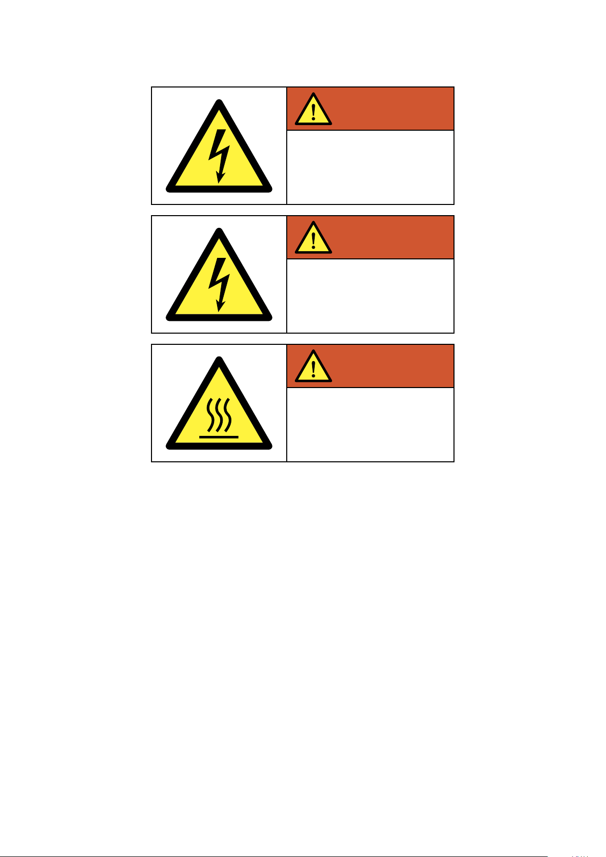
ABB2000IKI01
x
Installation manual
Ingeteam
WARNING
RISK OF ELECTRIC SHOCK
DO NOT REMOVE COVER.
No user serviceable parts inside.
Refer servicing to qualied
service personnel.
WARNING
RISK OF ELECTRIC SHOCK
FROM ENERGY IN CAPACITOR.
Do not remove cover until 5
minutes after disconnecting
all sources of supply.
WARNING
HOT SURFACES.
To reduce the risk of burns
do not touch.

ABB2000IKI01 xi
Installation manual Ingeteam
Table of Contents
1. Overview ...............................................................................................................................................14
1.1. Equipment description ....................................................................................................................14
1.1.1. Models ..................................................................................................................................14
1.1.2. Options .................................................................................................................................14
1.2. Configuration parameters ................................................................................................................15
1.2.1. Units with a transformer..........................................................................................................15
1.2.2. Units without a transformer (TL) ..............................................................................................16
1.3. Compliance with regulations ............................................................................................................17
2. System description .................................................................................................................................17
2.1. Location ........................................................................................................................................17
2.1.1. Environment...........................................................................................................................17
2.1.2. Protection class......................................................................................................................17
2.1.3. Ambient temperature ..............................................................................................................17
2.1.4. Atmospheric conditions...........................................................................................................18
2.1.5. Contamination class ...............................................................................................................18
2.1.6. Acoustic contamination...........................................................................................................18
2.1.7. Ventilation..............................................................................................................................18
2.1.8. Environmental characteristics ..................................................................................................19
2.2. Characteristics of the electrical installation .......................................................................................19
2.3. EMC requirements..........................................................................................................................19
2.4. Location of the components ............................................................................................................19
3. Operating, conservation and transport conditions.......................................................................................23
3.1. Symbols ........................................................................................................................................23
3.2. Equipment reception ......................................................................................................................23
3.3. Handling and unpacking ................................................................................................................24
3.4. Moving the equipment ....................................................................................................................25
3.5. Storage .........................................................................................................................................26
3.6. Conservation..................................................................................................................................27
3.7. Waste handling...............................................................................................................................27
4. Safety instructions .................................................................................................................................28
4.1. Symbols ........................................................................................................................................28
4.2. General safety precautions ..............................................................................................................28
4.3. General.........................................................................................................................................29
4.3.1. General risks existing and preventive measures..........................................................................30
4.3.2. Additional risks and measures in handling tasks .......................................................................30
4.4. Type of tasks to be carried out.........................................................................................................30
4.4.1. Inspection tasks .....................................................................................................................30
4.4.2. Handling tasks.......................................................................................................................30
4.4.3. Personal protection equipment (PPE) .......................................................................................31
4.5. Safety measures while working ........................................................................................................31
5. Installation ............................................................................................................................................33
5.1. General requirements for installation ................................................................................................33
5.2. Fixing the unit to the floor ...............................................................................................................33
5.3. Requirements for transformers and insulation monitor........................................................................36
5.3.1. Grid connection transformer (units without a transformer)...........................................................36
5.3.2. Auxiliary transformer ..............................................................................................................36
5.4. Insulation monitor (units without an ungrounded transformer) .............................................................37
5.5. Electrical connection ......................................................................................................................37
5.5.1. Description of cable inlets.......................................................................................................38
5.5.2. Description of cabling connections...........................................................................................39
5.5.3. Order of connecting the unit....................................................................................................39
5.5.4. Inverter wiring diagram ...........................................................................................................40
5.5.5. System wiring diagram............................................................................................................42
5.5.6. Insulation fault contact / grid connection indicator ....................................................................47
5.5.7. Access to auxiliary connections ............................................................................................... 48
5.5.8. Connection for communication via RS-485 serial port .............................................................. 48
5.5.9. Connection for communication via modem-GSM/GPRS + RS-485 .............................................. 48

ABB2000IKI01
xii
Installation manual
Ingeteam
5.5.10. Connection for Ethernet communication .................................................................................50
5.5.11. Ground connections .............................................................................................................50
5.5.12. Grid connection ...................................................................................................................51
5.5.13. Connecting to the PV array ....................................................................................................53
Units fitted with ground connection on the positive pole ..................................................................54
Units fitted with ground connection on the negative pole .................................................................54
Non-grounded units.....................................................................................................................55
5.6. Available kits .................................................................................................................................55
5.6.1. Nighttime power supply kit ......................................................................................................55
5.6.2. Remote triggering kit ..............................................................................................................56
5.6.3. Heating element kit................................................................................................................56
5.6.4. Auxiliary services kit...............................................................................................................57
5.6.5. Voltage fall-out kit..................................................................................................................57
5.6.6. Synchronization kit.................................................................................................................58
6. Commissioning ......................................................................................................................................60
6.1. Equipment inspection .....................................................................................................................60
6.1.1. Inspection..............................................................................................................................60
6.1.2. Shutting down........................................................................................................................60
6.2. Start-up ........................................................................................................................................61
6.2.1. Start-up ................................................................................................................................61
6.2.2. Checking and measurement ....................................................................................................61
7. Preventive maintenance...........................................................................................................................62
7.1. Maintenance tasks ..........................................................................................................................62
8. Display control.......................................................................................................................................65
8.1. Keypad and LEDs...........................................................................................................................65
8.2. Display..........................................................................................................................................66
8.3. Main menu....................................................................................................................................67
8.4. Monitoring.....................................................................................................................................67
8.5. Reasons for shutdown.....................................................................................................................68
8.6. Settings ........................................................................................................................................69
Date and Time ............................................................................................................................69
Inverter number change ...............................................................................................................69
Language ...................................................................................................................................69
Grid quality.................................................................................................................................70
Ground connection ......................................................................................................................70
Connection time..........................................................................................................................70
Total reset ..................................................................................................................................70
Other adjustments.......................................................................................................................70
Change NumCAN ........................................................................................................................70
8.7. Inverter data ..................................................................................................................................70
8.8. Change inverter number..................................................................................................................71
9. Troubleshooting......................................................................................................................................71
9.1. LED messages ...............................................................................................................................71
9.1.1. Green LED .............................................................................................................................71
Slow flashing ..............................................................................................................................71
Fast flashing ...............................................................................................................................71
Steady light ................................................................................................................................71
9.1.2. Orange LED ...........................................................................................................................72
Fast flashing ...............................................................................................................................72
9.1.3. Red LED................................................................................................................................72
Steady light ................................................................................................................................72
9.2. List of alarms and reasons for shutdown ...........................................................................................73
9.3. Inverter alarms due to protections ....................................................................................................74
9.4. Action protocol for responding to incidents........................................................................................74
9.4.1. Voltage and/or frequency out of range.......................................................................................75
9.4.2. Temperature ..........................................................................................................................77
9.4.3. AC circuit protection...............................................................................................................78
9.4.4. Reason for contactor shutdown................................................................................................79
9.4.5. DC circuit protections .............................................................................................................79
9.4.6. Insulation fault.......................................................................................................................79

ABB2000IKI01 xiii
Installation manual Ingeteam
External to the unit......................................................................................................................80
Internal to the unit ......................................................................................................................80
9.4.7. Manual shutdown ...................................................................................................................81
9.4.8. Protection of the switching filter ..............................................................................................81
9.5. Replacing the electronics block........................................................................................................81
9.6. Replacing varistors in the intake board ............................................................................................ 83
9.7. Description of terminal strip............................................................................................................ 84
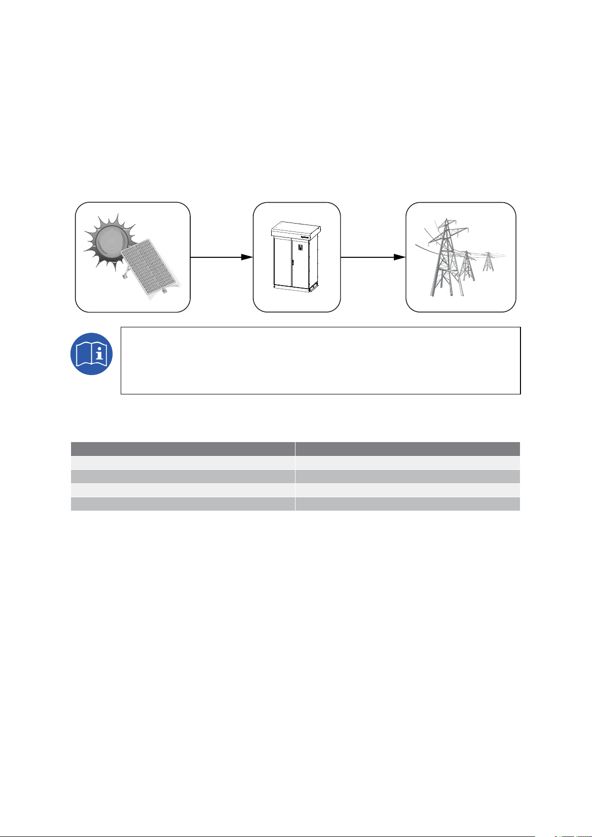
ABB2000IKI01
14
Installation manual
Ingeteam
1. Overview
The purpose of this manual is to describe the INGECON SUN Power U and to give appropriate information for its
correct receipt, installation, start-up, maintenance and operation.
1.1. Equipment description
An inverter is a circuit used to convert direct current to alternating current. The function of these units is to convert
the direct current generated by photovoltaic solar panels to alternating current and so enable it to be fed to the elec-
tricity grid.
Depending on installation requirements, the unit may be ordered:
• With ground connection on the positive pole.
• With ground connection on the negative pole.
• No grounding.
1.1.1. Models
The INGECON SUN Power U product family comprises units without a transformer (TL) and units with a transformer:
Units with a transformer Units without a transformer (TL)
INGECON SUN 125 U 208 Outdoor INGECON SUN 125 TL U 208 Outdoor
INGECON SUN 125 U 480 Outdoor INGECON SUN 165 TL U 275 Outdoor
INGECON SUN 200 TL U 330 Outdoor
INGECON SUN 220 TL U 360 Outdoor
1.1.2. Options
These models may include the following options:
• Nighttime power supply.
• Remote triggering kit.
• Heating element kit.
• Auxiliary services kit.
• Voltage fall-out kit.
• Synchronization kit.

ABB2000IKI01 15
Installation manual Ingeteam
1.2. Configuration parameters
1.2.1. Units with a transformer
DC input 125 U 208 125 U 480
Range of input operating voltage 330 ~ 920 V
Maximum input voltage 1000 V (1)
Maximum input current 390 A
Maximum input short circuit current 250 A (4 fused inputs)
Maximum input source backfeed current to input source 0 A
AC output 125 U 208 125 U 480
Output power factor rating > 0.99
Operating voltage range (ac) (L-L) 183 ~ 229 V 422.5 ~ 528 V
Operating frequency range or single frequency 57 ~ 60.5 Hz
Number of phases 3
Nominal output voltage (AC) 208 V 480 V
Normal output frequency 60 Hz
Maximum continuous output current (AC) per line 347 A 151 A
Rated power (AC) 125 kW
Maximum output fault current (ac) and duration 860 A at 11 ms 372 A at 6.5 ms
Maximum output overcurrent protection 600 A (MCB setting Q1) 225 A (MCB setting Q1)
Reconnection time 5 minutes
Normal operation temperature range -4 º F (-20 º) ~ 149 °F (65 °C)
Maximum full power operating ambient 122 °F (50 °C)
Enclosure Rating Type NEMA 3R
Utility interconnection voltage and frequency trip limits and trip times
Condition
Simulated utility source Maximum time (sec) at
60 Hz before cessation of
current to the simulated
utility
Voltage (V) Frequency (Hz)
A< 0.50 Vnor Rated 0.16
B0.50 Vnor ≤ V < 0.88 Vnor (Adjustable Set
Points, default 0.88 Vnor) Rated 0.16 ~ 2 (Adjustable Set
Points, default 0.16)
C1.10 Vnor < V < 1.20 Vnor (Adjustable Set
Points, default 1.10 Vnor) Rated 0.16 ~ 1 (Adjustable Set
Points, default 0.16)
D1.20 Vnor ≤ V Rated 0.16
ERated f > 60.5 0.16
FRated
f < (59.8 ~ 57.0)
(Adjustable Set Points, default
59)
0.16 ~ 300
GRated f < 57 0.16
Precision of values and disconnection time of the voltage and frequency protections.
Voltage ± 1%
Frequency ± 0.1 Hz
Time 0.06 s
(1) above 920 V the unit remains in standby.

ABB2000IKI01
16
Installation manual
Ingeteam
1.2.2. Units without a transformer (TL)
DC input 125 TL U 208 165 TL U 275 200 TL U 330 220 TL U 360
Range of input operating voltage 330 ~ 920 V 440 ~ 920 V 525 ~ 920 V 570 ~ 920 V
Maximum input voltage 1000 V (1)
Maximum input current 390 A
Maximum input short circuit current 250 A (4 fused inputs)
Maximum input source backfeed current to input source 0 A
AC output 125 TL U 208 165 TL U 275 200 TL U 330 220 TL U 360
Output power factor rating > 0.99
Operating voltage range (ac) (L-L) 183 ~ 229 V 242 ~ 303 V 290 ~ 319 V 317 ~ 396 V
Operating frequency range or single frequency 57 ~ 60.5 Hz
Number of phases 3
Nominal output voltage (AC) 208 V 275 V 330 V 360 V
Normal output frequency 60 Hz
Maximum continuous output current (AC) per line 347 A
Rated power (AC) 125 kW 165 kW 200 kW 220 kW
Maximum output fault current (ac) and duration 860 A at 11 ms
Maximum output overcurrent protection 600 A (MCB setting Q1)
Reconnection time 5 minutes
Normal operation temperature range -4 º F (-20 º) ~ 149 °F (65 °C)
Maximum full power operating ambient 122 °F (50 °C)
Enclosure Rating Type NEMA 3R
Utility interconnection voltage and frequency trip limits and trip times
Condition
Simulated utility source Maximum time (sec) at
60 Hz before cessation of
current to the simulated
utility
Voltage (V) Frequency (Hz)
A< 0.50 Vnor Rated 0.16
B0.50 Vnor ≤ V < 0.88 Vnor (Adjustable Set
Points, default 0.88 Vnor) Rated 0.16 ~ 2 (Adjustable Set
Points, default 0.16)
C1.10 Vnor < V < 1.20 Vnor (Adjustable Set
Points, default 1.10 Vnor) Rated 0.16 ~ 1 (Adjustable Set
Points, default 0.16)
D1.20 Vnor ≤ V Rated 0.16
ERated f > 60.5 0.16
FRated
f < (59.8 ~ 57.0)
(Adjustable Set Points, default
59)
0.16 ~ 300
GRated f < 57 0.16
Precision of values and disconnection time of the voltage and frequency protections.
Voltage ± 1%
Frequency ± 0.1 Hz
Time 0.06 s
(1) above 920 V the unit remains in standby.

ABB2000IKI01 17
Installation manual Ingeteam
1.3. Compliance with regulations
UL 1741
UL Standard for Safety for Inverters, Converters, Controllers and Interconnection System Equipment for Use With
Distributed Energy Resources, Second Edition, Dated Janauary 28, 2010.
CSA
CAN/CSA-C22.2 No. 0-M91 - General Requirements - Canadian Electrical Code - Part II.
0.4-04 - Bonding of Electrical Equipment.
107.1-01 - General Use Power Supplies.
IEEE 1547.1TM
IEEE Standard Conformance Test Procedures for Equipment Interconnecting Distributed Resources with Electric
Power Systems.
FCC Part 15 B (class A) EMC tests
2. System description
2.1. Location
These units must be installed in environments with specific characteristics.
Guidelines are provided in this section for choosing a suitable environment and adapting the unit to it properly.
2.1.1. Environment
Place the units in a place which is accessible for installation and maintenance work and which
permits use of the keyboard, the display and the reading of the front indicator LEDs.
A minimum space of 40 in (1 m) must be maintained on both sides and in front and behind the unit
to allow the free circulation of air through the circulation vents.
The air vents and part of the cabinet close to them can reach 185 °F (85 °C). Do not place any
material nearby which is sensitive high air temperatures.
Avoid corrosive environments that may affect the proper operation of the inverter.
Never place any object on top of the unit.
2.1.2. Protection class
These units meet NEMA type 3R degree of protection against external agents.
They are therefore designed to be suitable for outdoor location.
2.1.3. Ambient temperature
These units are designed to operate in a temperature range from -4 °F (-20 °C) to 149 °F (65 °C). Nominal power
may be input at up to 122 °F (50° C). Above this temperature the unit limits input power in order to cool the internal
temperature of the electronics.
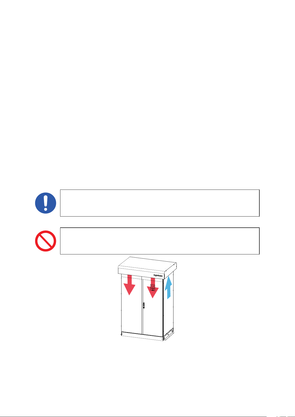
ABB2000IKI01
18
Installation manual
Ingeteam
2.1.4. Atmospheric conditions
The ambient air must be clean and relative humidity must not exceed 50% at over 104 °F (40 °C). Higher levels of
relative humidity, up to 95%, can be tolerated at below 86 °F (30 °C).
It should be borne in mind that moderate condensation may occasionally occur as a consequence of temperature
variations. For this reason, apart from the unit’s own protection, vigilance of these units is necessary once they have
been started up on sites where the conditions described above are not expected to be present.
In the event of condensation, never apply voltage to the unit.
2.1.5. Contamination class
The pollution class for which the units have been designed is grade 3.
Suitable measures should be taken to provide dust-free air of sufficient quality in the vicinity of the inverter.
2.1.6. Acoustic contamination
When on, the inverter generates a buzzing sound.
Do not place it in an occupied room, or on light supports which might amplify this buzz. The mounting surface must
be firm and appropriate for the weight of the unit.
2.1.7. Ventilation
These units intake air through the sides of the housing and expel it from the front and back.
A minimum obstacle-free space of 40 in (1 m) must be maintained on both sides as well as in front of and behind the
unit to allow the free circulation of air.
These units are fitted with two cooling fans on the top of the cabinet. These fans start up for a few
seconds each time the inverter is connected to the mains and is about to inject power. This procedure
makes it possible to easily check proper operation.
The fans require an adequate flow of clean, dust-free air for proper operation.
Do not place any object on top of the unit.

ABB2000IKI01 19
Installation manual Ingeteam
2.1.8. Environmental characteristics
The environmental conditions for operation are:
Ambient conditions
Minimum temperature (1) -4 °F (-20 °C)
Minimum surrounding air temperature (1) -4 °F (-20 °C)
Minimum surrounding air temperature 149 °F (65 °C)
Temperature at which power limiting commences 122 °F (50 °C)
Maximum relative humidity without condensation 95%
(1) Units including a heating element kit may be installed in locations with a minimum temperature of -13 °F (-25 °C).
For further information see Chapter “2.4. Location of the components”.
2.2. Characteristics of the electrical installation
These units are designed to be connected to the low voltage public grid.
2.3. EMC requirements
These units are equipped with the necessary filtering elements to comply with EMC requirements for industrial appli-
cations in order to prevent disturbances in other equipment outside the installation.
2.4. Location of the components
See next pages.
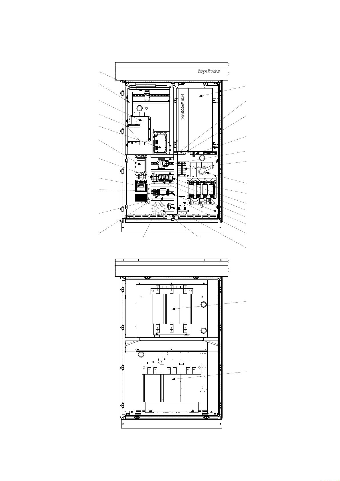
ABB2000IKI01
20
Installation manual
Ingeteam
INGECON SUN 125 U 208 Outdoor
Shock absorbing
resistors
Q2
Harmonic filter
AC contactor
AC thermomagnetic
circuit breaker
Ground connection
fuse
Inductance
Transformer
* Optional
Q4
XAUX
QAUX
DC arresters
Heating
element*
DC breaker
EMC filter
EMI DC filter
Electronics block
DC fuses
DC plates
Electronics block AC
plates
DC fuses
+15 Vdc supply Auxiliary service
transformer*
X7
X9
X8
AC arresters
SAC*
EMI AC filter
This manual suits for next models
5
Table of contents
Other Ingecon Inverter manuals


Popular Inverter manuals by other brands


BARRON
BARRON EXITRONIX Tucson Micro Series installation instructions

Baumer
Baumer HUBNER TDP 0,2 Series Mounting and operating instructions

electroil
electroil ITTPD11W-RS-BC Operation and Maintenance Handbook

Silicon Solar
Silicon Solar TPS555-1230 instruction manual

Mission Critical
Mission Critical Xantrex Freedom SW-RVC owner's guide

HP
HP 3312A Operating and service manual


