manuals.online logo
Brands
  1. Home
  2. •
  3. Brands
  4. •
  5. Ingersoll-Rand
  6. •
  7. Tools
  8. •
  9. Ingersoll-Rand D Series Setup guide

Ingersoll-Rand D Series Setup guide

16574238
Edition 2
May 2014
Save These Instructions
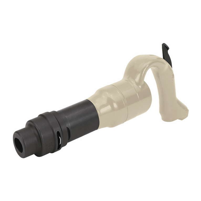
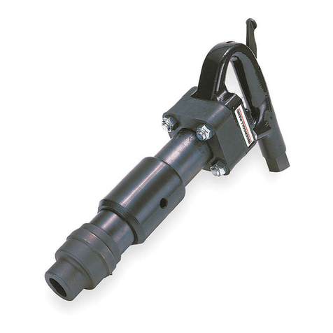
Air Percussive Chipping Hammer
“D” Series and MDT3-EU
Maintenance Information
2 16574238_ed2
Product Safety Information
WARNING
Failure to observe the following warnings, and to avoid these potentially hazardous situations, could result in death or serious
injury.
Read and understand this and all other supplied manuals before installing, operating, repairing, maintaining, changing accessories
on, or working near this product.
Always wear eye protection when operating or performing maintenance on this tool. The grade of protection required should be
assessed for each use and may include impact-resistant glasses with side shields, goggles, or a full face shield over those glasses.
Always turn o the air supply, bleed the air pressure and disconnect the air supply hose when not in use, before installing, removing
or adjusting any accessory on this tool, or before performing any maintenance on this tool or any accessory.
Note: When reading the instructions, refer to exploded diagrams in parts Information Manuals when applicable (see under Related Documentation
for form numbers).
Lubrication
•
•
•
•
Each time a “D”Series or MDT3-EU Hammer is disassembled for
maintenance and repair or replacement of parts, pour about 3 cc of
Ingersoll Rand No. 10 Oil in the air inlet and operate the tool for
5 seconds to coat the internal parts with oil.
Weekly, ush the Tool and lubricate immediately afterwards as
instructed in PLACING THE TOOL IN SERVICE.
Loss of power and excessive air consumption may be due to wear on
the Piston (16) and the bore of the Barrel (17). This can be determined
by checking the Piston diameter at each end and in the center with
a micrometer. If the diameter at the center is .003” greater than the
diameter at either end, it is proof that the Piston and Barrel are worn.
To correct, lap the Barrel and install an oversize Piston as instructed
below, under Installation of Oversize Piston.
Oversize Parts
The Piston (16), Nozzle (21) and Inlet Bushing (9) can be furnished
oversize as well as standard size. When properly installed, oversize
parts renew the eciency of the Hammer as well as lengthen its life.
See Installation of Oversize Piston on Page 3.
Disassembly
General Instructions
Do not disassemble the tool any further than necessary to replace
or repair damaged parts.
Whenever grasping a tool or part in a vise, always use leather-
covered or copper-covered vise jaws to protect the surface of
the part and help prevent distortion. This is particularly true of
threaded members and housings.
Do not remove any part which is a press t in or on a subassembly
unless the removal of that part is necessary for repairs or replace-
ment.
Do not disassemble the tools unless you have a complete set of
new gaskets and O-rings for replacement.
Disassembly of the Handle and Throttle Mechanism
Remove the Lock Spring (24A or 27) from the Retainer (24 or 28).
Using a vise with leather covered or copper covered jaws, clamp
the tool by the Barrel (17) with the Handle (1) up.
To remove the Throttle Lever (2), drive out the Roll Pin (3) using a
suitable pin punch.
Unscrew the Inlet Bushing (9) and remove the Air Strainer (7),
Throttle Valve Spring (6), Throttle Valve Ball (5) and Throttle Valve
Plunger (4).
Disassembly of the Barrel Piston and Nozzle
With the Barrel clamped in the vise as above, use two 3/4”
wrenches and remove the four Nuts (20) which secure the Handle
to the Barrel. The Handle can now be removed from the Barrel.
1.
2.
3.
4.
1.
2.
3.
4.
1.
If necessary, pull out Roll Pins (15). Remove the Valve Seat (14),
Valve (13), Valve Spacer (12), Valve Cap (11) and Valve Sealing
O-ring (10).
Remove the Barrel from the vise and invert it to allow the
Piston (16) to slide out.
Remove the Nozzle (21), using tool, Part No. H02-119 Nozzle
Ejection Arbor. Support the end of the Barrel and press out the
old Nozzle.
NOTICE
During the life of the tool, it is unlikely that the Collar (19) or
Exhaust Deector (22) will need to be separated from the Barrel.
Should this be necessary, the following sequence should be
followed.
Disassembly of the Collar
Grip the Barrel in a vise equipped with soft jaws so that the barrel
is horizontal.
Remove the four Bolts (23) from the Collar.
The Collar can now be slid along the Barrel and removed.
Disassembly of the Deector
The Exhaust Deector (22) is a snap t into a wide groove around
the Barrel. If it needs to be removed, it must be pressed out of
the groove using a tube or similar of a suitable diameter to clear
the Barrel.
If the Deector is not to be reused, it can be cut free of the Barrel.
2.
3.
4.
1.
2.
3.
1.
Assembly
General Instructions
Whenever grasping a tool or part in a vise, always use leather-
covered or copper-covered vise jaws. Take extra care with
threaded parts and housings.
Always clean every part and wipe every part with a thin lm of oil
before installation.
Apply a lm of O-ring lubricant to all O-rings before nal
assembly.
1.
2.
3.
Assembly of the Barrel, Piston and Nozzle
If the Nozzle (21) has been removed it should now be replaced.
Stand the Barrel, tapered end up beneath a press and locate the
Nozzle with the lead in towards the bore. Make sure that the
nozzle sits square to the bore. Use a soft mallet to start the nozzle
and press home.
1.
16574238_ed2 3
NOTICE
The 19 mm Hex Nozzle is fully home when it is approximately
7 mm (0.750”) below the end surface of the Barrel.
NOTICE
For hexagonal nozzles, be sure to orient the nozzle to the desired
position.
2. Reposition the Barrel in the vise so that it is clamped vertically
collar to the top. Lubricate the surface lightly with Ingersoll Rand
No. 10 Oil and insert Piston (16) in the bore, small end rst.
3. Assemble Valve components in the following sequence by
placing each over the Roll Pins (15) in the Barrel face: Valve
Seat (14), Valve (13) , Valve Spacer (12) and Valve Cap (11).
4. Lightly grease the Valve Sealing O-ring (10) to hold it in place in
its groove in the Handle (1) and replace the Handle over the Valve
Assembly.
5. Align the bolt holes in the Handle with the holes in the Collar (19)
and replace the four Bolts (23). Thread new Nyloc Nuts (20) on
each bolt and tighten down gradually and evenly to a torque of
40 ft/lbs (54 Nm).
NOTICE
Make sure that the Valve Sealing O-ring is still in place in its
groove before tightening the nuts. The handle can distort
causing the tool to leak air if the tightening process is not done
evenly and to the correct torque.
Assembly of the Handle and Throttle Mechanism
Align the pivot hole of the Throttle Lever (2) with the correspond-
ing pin hole in the Handle and secure in place with Roll Pin (3).
Use a pin punch to bury the Pin below the Handle surface.
Install the Throttle Valve Plunger (4) in the bore of the Handle
followed by the Throttle Valve Ball (5).
Locate the small end of Throttle Valve Spring (6) on the Throttle
Valve Ball. Replace the Air Strainer (7) with the raised portion in-
side the Spring. Secure everything in place with the Inlet Bushing
1.
2.
3.
(9). Coat the threads of the Inlet Bushing with a suitable thread
locking compound. Tighten the Bushing to a torque of
35 ft/lbs (47 Nm).
NOTICE
Over-tightening of the Bushing may cause stripping of the
Bushing threads in the Handle.
4. Install the Retainer (24 or 28) on the front of the Barrel and secure
in place with Locking Spring (24A or 27).
Retting of the Collar
To ret the Collar (19) to the Barrel (17), slide the Collar along the
Barrel and line up slot on Barrel with protrusion inside of collar.
Tap Collar with rubber mallet until secure.
Retting the Exhaust Deector
To ret the Exhaust Deector (22), lightly lubricate the front large
diameter of the Barrel with liquid soap or O-ring lubricant. Then
push the Exhaust Deector along the Barrel until it snaps into
position in its retaining groove.
NOTICE
The Exhaust Deector can be rotated to direct the exhaust
stream away from the operator.
Installation of Oversize Piston
NOTICE
Do not install an oversize Piston without rst lapping the Barrel.
Greater wear occurs near the center of the barrel bore than at either
end. To obtain full benet from an oversize Piston (16), it is necessary
to lap the Barrel (17) until the bore is of uniform size for its entire
length. Select and install the proper size Piston after truing up the
Barrel bore. Pistons are furnished .004”or .008”, .012” or .016”oversize.
1.
2.
1.
Maintenance Tools
Tool Number for Ordering Tool Name for Ordering Operation
H02-119 Nozzle Ejection Arbor Remove Nozzle (21) from the Barrel (17).
Troubleshooting Guide
Trouble Probable Cause Solution
Sluggish operation Dirt or oil gum accumulation on internal
parts
Pour about 3 cc of a clean, suitable, cleaning
solution into the air inlet and operate for 30
seconds. After ushing, pour about 3 cc of
oil into the air inlet and operate the tool for
5 seconds to coat the internal parts with oil.
Loss of power Worn Valve Replace the Valve.
Loss of eciency Worn Piston and/or accessory Replace Piston and or accessory.
Related Documentation
For additional information refer to:
Air Percussive Chipping Hammer Product Safety Information Manual 04581450.
Air Percussive Chipping Hammer Product Information Manual 16574154.
Air Percussive Chipping Hammer Parts Information Manual 16574311.
Manuals can be downloaded from ingersollrandproducts.com
ingersollrandproducts.com
© 2014 Ingersoll Rand

Other manuals for D Series

2

This manual suits for next models

13

Other Ingersoll-Rand Tools manuals

Ingersoll-Rand 132 Setup guide

Ingersoll-Rand

Ingersoll-Rand 132 Setup guide

Ingersoll-Rand 6WRSL3 User manual

Ingersoll-Rand

Ingersoll-Rand 6WRSL3 User manual

Ingersoll-Rand PowerForce PF600 User manual

Ingersoll-Rand

Ingersoll-Rand PowerForce PF600 User manual

Ingersoll-Rand 326G User manual

Ingersoll-Rand

Ingersoll-Rand 326G User manual

Ingersoll-Rand 2934B2SP-EU User manual

Ingersoll-Rand

Ingersoll-Rand 2934B2SP-EU User manual

Ingersoll-Rand A Series User manual

Ingersoll-Rand

Ingersoll-Rand A Series User manual

Ingersoll-Rand A Series User manual

Ingersoll-Rand

Ingersoll-Rand A Series User manual

Ingersoll-Rand 1-EU Series User manual

Ingersoll-Rand

Ingersoll-Rand 1-EU Series User manual

Ingersoll-Rand 2141 Setup guide

Ingersoll-Rand

Ingersoll-Rand 2141 Setup guide

Ingersoll-Rand 115 Series User manual

Ingersoll-Rand

Ingersoll-Rand 115 Series User manual

Ingersoll-Rand 99V60P107 User manual

Ingersoll-Rand

Ingersoll-Rand 99V60P107 User manual

Ingersoll-Rand 324 Series User manual

Ingersoll-Rand

Ingersoll-Rand 324 Series User manual

Ingersoll-Rand PowerForce PF600 User manual

Ingersoll-Rand

Ingersoll-Rand PowerForce PF600 User manual

Ingersoll-Rand 2904P1 User manual

Ingersoll-Rand

Ingersoll-Rand 2904P1 User manual

Ingersoll-Rand 2200 Series Setup guide

Ingersoll-Rand

Ingersoll-Rand 2200 Series Setup guide

Ingersoll-Rand AVC10 User manual

Ingersoll-Rand

Ingersoll-Rand AVC10 User manual

Ingersoll-Rand 9001-EU User manual

Ingersoll-Rand

Ingersoll-Rand 9001-EU User manual

Ingersoll-Rand 2934P2 User manual

Ingersoll-Rand

Ingersoll-Rand 2934P2 User manual

Ingersoll-Rand 2DA Series User manual

Ingersoll-Rand

Ingersoll-Rand 2DA Series User manual

Ingersoll-Rand D Series User manual

Ingersoll-Rand

Ingersoll-Rand D Series User manual

Ingersoll-Rand A Series Setup guide

Ingersoll-Rand

Ingersoll-Rand A Series Setup guide

Ingersoll-Rand ARO AG0 Series User manual

Ingersoll-Rand

Ingersoll-Rand ARO AG0 Series User manual

Ingersoll-Rand 3103XP User manual

Ingersoll-Rand

Ingersoll-Rand 3103XP User manual

Ingersoll-Rand 2925P1Ti Series User manual

Ingersoll-Rand

Ingersoll-Rand 2925P1Ti Series User manual

Popular Tools manuals by other brands

MSW MSW-ETT-23 user manual

MSW

MSW MSW-ETT-23 user manual

Sumake PN-5332P manual

Sumake

Sumake PN-5332P manual

Josef Kihlberg JK20-690 operating instructions

Josef Kihlberg

Josef Kihlberg JK20-690 operating instructions

Atlas Copco 4210 4480 90 Instruction supplement

Atlas Copco

Atlas Copco 4210 4480 90 Instruction supplement

National Instruments SCB-100A user guide

National Instruments

National Instruments SCB-100A user guide

Wen MB500 instruction manual

Wen

Wen MB500 instruction manual

Teseq NSG 437 user manual

Teseq

Teseq NSG 437 user manual

infaco Electrocoup F3015 instructions

infaco

infaco Electrocoup F3015 instructions

Wolf Garten Simplex Plus instruction manual

Wolf Garten

Wolf Garten Simplex Plus instruction manual

Energizer EZMO160-210 user guide

Energizer

Energizer EZMO160-210 user guide

XTline XT41900 user manual

XTline

XTline XT41900 user manual

Ryobi RT100 Operator's manual

Ryobi

Ryobi RT100 Operator's manual

Chicago Pneumatic CP714 Operator's manual

Chicago Pneumatic

Chicago Pneumatic CP714 Operator's manual

Alemite 596 Series User and maintenance instructions

Alemite

Alemite 596 Series User and maintenance instructions

Cornwell Tools GG-CSGGA operating instructions

Cornwell Tools

Cornwell Tools GG-CSGGA operating instructions

U-Line H-3069 manual

U-Line

U-Line H-3069 manual

Sealey Auto Service VS392 instructions

Sealey

Sealey Auto Service VS392 instructions

Scell-it ELEMENT EIGHT 8 user manual

Scell-it

Scell-it ELEMENT EIGHT 8 user manual

manuals.online logo
manuals.online logoBrands
  • About & Mission
  • Contact us
  • Privacy Policy
  • Terms and Conditions

Copyright 2025 Manuals.Online. All Rights Reserved.