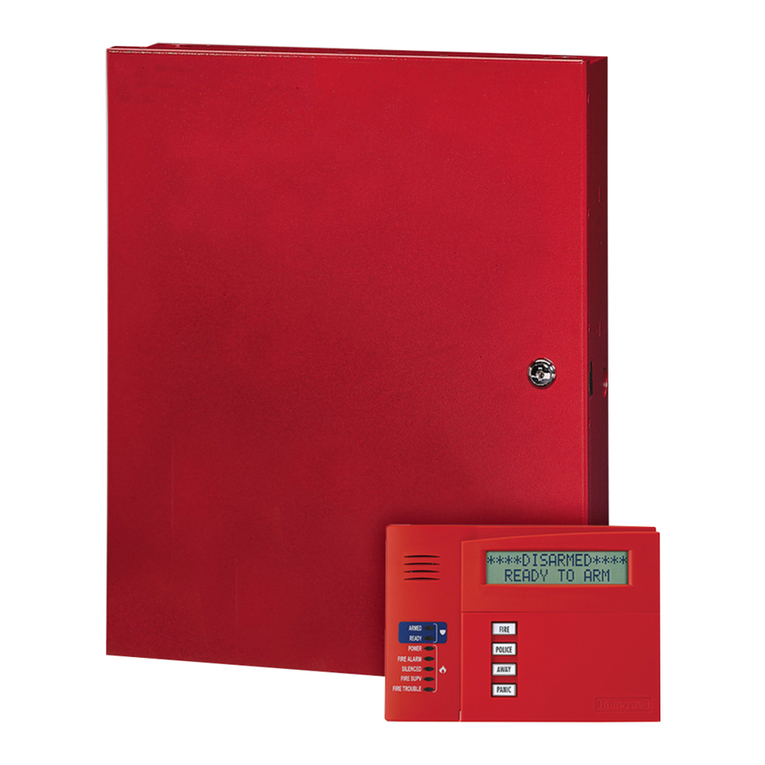
Inhep Digital Security IDS X Series User manual


2
700-398-01J X-Series User Manual Issued for version 2.8x

3
700-398-01J X-Series User Manual Issued for version 2.8x
Contents
1. Introduction to the IDS X-Series Alarm Panel........................................................................................ 6
Keypad Indicator Icons ............................................................................................................... 8
Button Details ............................................................................................................................. 8
Viewing Data on an LED Keypad................................................................................................. 9
Numerical Values........................................................................................................................ 9
Reading Binary Values .............................................................................................................. 10
Entering Data on an LED Keypad .............................................................................................. 10
2. The Keypad Buzzer............................................................................................................................... 11
3. Arming the Alarm................................................................................................................................. 11
Away Arm.................................................................................................................................. 11
Stay Arm.................................................................................................................................... 12
Key-switch or Remote Arming (If Fitted).................................................................................. 13
Auto Arm................................................................................................................................... 14
4. Disarming the Control Panel................................................................................................................ 14
How to Disarm with a User Code.............................................................................................. 14
How to Disarm Using a Key-switch or Remote......................................................................... 14
5. Bypassing Zones................................................................................................................................... 14
Fire Alarms................................................................................................................................ 15
Panic.......................................................................................................................................... 15
Medical Alarms ......................................................................................................................... 15
Duress Alarms........................................................................................................................... 15
6. Alarm Memory..................................................................................................................................... 16
7. Event Log.............................................................................................................................................. 16
8. Master User Program Options............................................................................................................. 16
Accessing the Master User Program Options........................................................................... 16
9. User Program Mode ............................................................................................................................ 17
Add a New User Code –Option 0............................................................................................. 17
Edit a Selected User Code –Option 1....................................................................................... 18
Delete a User Code –Option 2 (Code Known) ......................................................................... 18
Add/Edit Slot –Option 3........................................................................................................... 19
Delete a User Code –Option 4 (Slot Known)............................................................................ 19
View a User Code Slot Number –Option 5............................................................................... 20
User Code Properties –Option 10............................................................................................ 20
Assign a User Code to Partitions –Option 11 (Advanced) ....................................................... 22
Allow the Installer Code to Access the User Menu - Option 12............................................... 23
User Outputs –Option 13 (Advanced) ..................................................................................... 23
10. Xwave2Bi-directional Wireless............................................................................................................ 24
Wireless Bi-Directional Remote Identification ......................................................................... 24
Wireless Bi-directional Device Battery Check........................................................................... 24
Adding the Remote Transmitter to a User code –Option 16................................................... 25
Allocating Remote Transmitter Button Functions - Option 17................................................. 25
Deleting Bi-Directional Remote Transmitters –Option 18....................................................... 26
Bi-Directional Remote Transmitter LED.................................................................................... 26
Querying the X-Series via the Bi-Directional Remote Transmitter........................................... 26
Bi-Directional PIR Devices Walk test mode –Option 19 .......................................................... 27
11. Remote Receiver –Options 20 –29 (Advanced)................................................................................. 27
Add Remote to Panel –Option 20............................................................................................ 27
Add Remote to Panel –Advanced ............................................................................................ 28
Delete Remote from Panel ....................................................................................................... 30
Set Remote Receiver Button Properties................................................................................... 30
Set Remote Receiver Relay Properties ..................................................................................... 31
Set Remote Receiver Relay Pulse Time .................................................................................... 32
Defaulting the Remote Receiver............................................................................................... 33

4
700-398-01J X-Series User Manual Issued for version 2.8x
Identify Remote Receiver ......................................................................................................... 33
Remote Receiver Test............................................................................................................... 34
Remote Receiver Capacity........................................................................................................ 35
12. LCD Keypad Zone Naming –Option 30 (Advanced) ............................................................................ 35
13. LCD Keypad Language –Option 31...................................................................................................... 36
14. aXess .................................................................................................................................................... 36
Add/Edit Access Tags by number –Option 32 ......................................................................... 36
Option 33: Adding Access Tag by swiping the tag.................................................................... 36
Delete Access Tags by number –Option 34 ............................................................................. 36
Delete Access Tags via Swipe - Option 35 ................................................................................ 37
View Access Door Logs –Option 36 ......................................................................................... 37
aXess Reader LEDs .................................................................................................................... 37
15. Serial Code –Option 37 (X-Series 2.72 & above) ................................................................................ 39
16. Renaming Switch 1 –9 Function (X-Series 2.80 & above and Touch keypad 860-03-613)................. 39
17. Edit the Time - Option 40..................................................................................................................... 39
18. Edit the Date - Option 41..................................................................................................................... 40
19. Stay Zones............................................................................................................................................ 40
How to Select a Stay Profile...................................................................................................... 41
How to Program Stay Zones ..................................................................................................... 41
20. Buzz Zones ........................................................................................................................................... 42
How to Program a Buzz Zone.................................................................................................... 42
21.Chime Zones ........................................................................................................................................ 42
How to Program Chime Zones.................................................................................................. 43
22. Viewing Trouble Conditions................................................................................................................. 43
Explanation of Trouble Conditions ........................................................................................... 44
23. Changing a Partition ............................................................................................................................ 45
24. Output Control via a Keypad ............................................................................................................... 45
25. Maintenance Code - Advanced............................................................................................................ 46
Locations................................................................................................................................... 46
26. Programming Quick Reference Guide ................................................................................................. 50
Quick Reference User Guide..................................................................................................... 50
LED Keys.................................................................................................................................... 52
View Trouble Conditions........................................................................................................... 52

5
700-398-01J X-Series User Manual Issued for version 2.8x
Glossary
Alarm Memory
This is the history of the most recent events that occurred the last time the system was armed.
Arm
Arming the system sets the system into the ARMED mode. In this mode, violating a zone will activate an
alarm condition. If the system is programmed correctly, this will cause the appropriate reporting code to be
sent to the monitoring company.
Bypass
Bypassing deactivates a zone. When the panel is ARMED, violation of a bypassed zone will be ignored.
Disarm
Disarming the system sets the system into the DISARMED mode. Fire, medical and panic functions remain
active while the system is disarmed.
Entry/Exit Zones
These are zones that you pass through during the entry/exit delay period without triggering an alarm. Their
purpose is to provide a means by which you can exit after arming the system –and a means of getting to the
keypad to disarm after gaining access to the premises.
Follower Zone
A zone that may be violated during the Exit Zone delay period or after a violation of an Entry/Exit zone. This
allows the user (limited time) access to disarm the system, and sufficient time to exit before arming comes
into effect. A Follower zone will behave as per an Instant zone if violated prior to the violation of an
Entry/Exit zone.
Instant Zone
When the system is armed, violation of an Instant Zone will immediately cause an alarm condition to be
registered.
Partition
A partition is a group of zones that may be armed and disarmed independently without affecting zones or
users assigned to other partitions. The Alarm Panel may have been programmed by your installer to have up
to 8 partitions. Typically, a guest cottage appended to a main house may be partition 2, and the main house
partition 1.
Stay Arm
This is an arming mode that allows certain pre-programmed, Stay zones to be bypassed (temporarily
disabled) while the system is armed. If you arm the system and do not leave the premises within the exit
delay, the system will assume that you are staying home and will stay arm.
Stay Arm and Go
Arming that allows the user to Stay arm and leave the premises.
Stay Zone
A zone that is bypassed automatically when the system is Stay armed.
Violate
A zone is “violated” when a sensor connected to a zone input registers a door opening, a window opening,
somebody moving in the room, or glass breaking –depending on the sensor for that zone.
Zone
A zone is a specific area of your premises monitored by a sensor that detects violations (doors/windows
opening or people moving) in that area.

6
700-398-01J X-Series User Manual Issued for version 2.8x
1. Introduction to the IDS X-Series Alarm Panel
Congratulations on your purchase of an IDS Alarm Panel to protect your most valued possessions.
The IDS X-series is a versatile and expandable range of alarm panels with 8 partitions and can be expanded to
monitor up to 64 zones depending on the model. Most features are optional and may be programmed directly
through the keypad. There is a dedicated panic zone, monitored siren output, auxiliary power outputs and 5
(expandable to 57) programmable outputs that may be programmed to perform various trigger/switching
functions. These can all be programmed by your installer.
For correct operation, these Alarm Panels must be used in conjunction with the specified transformer/battery
combination and appropriate peripheral sensors and signalling devices.
Before Operating Your Alarm System
Read the entire manual carefully and keep it in an accessible place.
Note that this is not a DIY product, and your security system should be installed and serviced by a
qualified security professional who should instruct you regarding the level of protection provided and
the operation of the system.
Should you have any questions regarding the operation of the system, contact your installer.
Note that your system should be tested on a regular basis. Before testing the system, please notify your
security company of your intention to do so.
NEVER disconnect the mains power, as the back-up battery will eventually discharge thereby causing
the control panel to shut down.
Note that a security system cannot prevent emergencies. It is only intended to alert you and (if
applicable) your central monitoring station, of an emergency situation.
Note that smoke and heat detectors may not detect all fire situations.
This manual is not a fully detailed installation manual –the installation manual is only available to
accredited installers.
Note that the performance of your alarm system will to a large extent be determined by the quality and
installation of the detectors attached to your panel.
Understanding the Keypad
Figure 1: Classic LED Keypad

7
700-398-01J X-Series User Manual Issued for version 2.8x
Figure 2: Curve LED Keypad
Figure 3: Curve LCD Keypad

8
700-398-01J X-Series User Manual Issued for version 2.8x
Figure 4: Touch Keypad
Keypad Indicator Icons
Power indicator icon has two functions:
1. When the icon is on, this indicates the keypad is powered up.
2. Flashing indicates an issue has occurred and needs your attention.
Armed icon indicates the system is armed either in ‘away’ or ‘stay’ mode. The LCD will
display the armed mode.
Unarmed icon will be illuminated when the system is not armed.
Alarm icon will flash when an alarm condition has occurred.
Button Details
Partition Button is to select a partition that you would like to interact with via the keypad.
NOTE: Only available if the keypad is configured as a global keypad!
Stay Button allows you to select which stay profile to stay arm the system with.
NOTE: Only available if more than one stay profile has been programmed. (see X-Series user
manual)
Switch Button has two functions:
1. Access to outputs that could be used to switch devices, lights on/off or open/close gates, etc.
(Function not currently implemented)
Bypass button allows you to disable zones so that they cannot violate the alarm.
Chime button selects which zones, will cause the keypad to chime when violated while the system is
disarmed.
Navigation buttons allows you to scroll through menus, and when editing zone names, etc.
Press and hold left arrow buttons to change the keypad sounds.
Panic button when held down for 3 seconds will sound the siren and send a panic signal to the
security company if the alarm is configured to do so.
LCD Display
Power, Armed, Unarmed, Alarm Indicators
Touch keys

9
700-398-01J X-Series User Manual Issued for version 2.8x
Viewing Data on an LED Keypad
Table 1 shows the LED status indicators and the meaning of their various states.
Table 1: LED Indicators
ARM LED
(red)
READY LED
(green)
POWER LED
(red)
AWAY LED
(red)
ZONE LED
(amber)
DESCRIPTION
System Armed in Away Mode
System Armed in Stay Mode
System is Ready to be Armed
System Not Ready for Arming
Alarm Condition
(Check Alarm Memory zone
details BEFORE re-arming)
Mains Power is Present
Mains Power has Failed
Trouble Condition
Zone Bypassed
Zone Clear
Zone Violated or Tampered
= on = off = flashing
Numerical Values
Simple numerical values are represented via the zone LEDs. For instance, if zone LED 15 is on, it is representing
a value of 15. This is commonly used when enabling and disabling bitmapped locations. Each zone LED directly
corresponds to a number of the same value. For numbers or information that exceeds a value of 16, binary-
coded decimal values are used, as explained in the following sections.

10
700-398-01J X-Series User Manual Issued for version 2.8x
Reading Binary Values
Values within a data program location will be displayed by the zone LEDs in binary coded decimal format i.e.
zone LEDs 1-4 indicate units (ones) and zone LEDs 5-8 indicate tens (tens), and so on. To read a binary value on
the keypad, add up the values represented by each lit LED as shown in Table 2.
Table 2: Values Represented by each Zone LED
Zone LED
Value
Digit
Zone LED
Value
Digit
Zone 1
1
Units
Zone 9
1
Hundreds
Zone 2
2
Zone 10
2
Zone 3
4
Zone 11
4
Zone 4
8
Zone 12
8
Zone 5
1
Tens
Zone 13
1
Thousands
Zone 6
2
Zone 14
2
Zone 7
4
Zone 15
4
Zone 8
8
Zone 16
8
EXAMPLE:
Imagine the following zone LEDs are on: Zone 1, Zone 3 and Zone 5.
Units are represented by the sum of Zone 1 and Zone 3 (i.e. 1 + 4).
Tens of units are represented by the value of Zone 5 (i.e. 1 x ten).
Therefore, the displayed value is (1+4) + (10) = 15.
Values within a time program location are displayed in a similar format as per Table 3.
Table 3: Binary Coded Decimal Four Digit Display
Zone LED
Calculation
Unit
Zone LED
Calculation
Unit
1
(x 1 = 1)
m
9
(x 1 = 1)
s
2
(x 2 = 0)
10
(x 2 = 2)
3
(x 4 = 4)
11
(x 4 = 4)
Mm:Ss
4
(x 8 = 0)
12
(x 8 = 0)
= 54:43
5
(x 1 = 1)
M
13
(x 1 = 1)
S
m = LEDs 4 through 1
6
(x 2 = 0)
14
(x 2 = 0)
M = LEDs 5 through 8
7
(x 4 = 4)
15
(x 4 = 1)
s = LEDs 12 through 9
8
(x 8 = 0)
16
(x 8 = 0)
S = LEDs 16 through 13
Using an LCD keypad means that data and time information can be read directly without a need to convert.
Entering Data on an LED Keypad
Data is easily entered on a keypad. Below is a list of keys and their functions.
[*] –This key is used as an enter key, to confirm the data that you have inputted. It is also used to scroll to the
next sub-location.
[#] –This key is used to clear data that is incorrect. It can also be used to exit a programming option.
[F] –This key is used if there is a fire emergency. If programmed to do so, the fire reporting code will be sent to
your monitoring company.
[M] –This key is used if there is a medical emergency. If programmed to do so, the medical reporting code will
be sent to your monitoring company.
[P] –This key is used if there is an emergency situation that requires emergency personnel to respond. A panic
alarm will be transmitted to your monitoring company.
[0] to [9] –Keys marked 1 through 9, and including 0, are used to input data into the programming options.

11
700-398-01J X-Series User Manual Issued for version 2.8x
2. The Keypad Buzzer
[#] WITH any key from [0] to [6] for 1 second
The keypad includes a buzzer that is used for audible signalling and verification of certain keypad functions.
There are 7 possible volume settings: loud being the default setting. To program the keypad volume, use Table
4.
Table 4: Keypad Buzzer Settings
Key Entry
Keypad Buzzer Sound
Key Entry
Keypad Buzzer Tone
[#] [3]
Loud (Default setting)
[#] [6]
2kHz (High)
[#] [2]
Medium
[#] [5]
1kHz (Medium)
[#] [1]
Soft
[#] [4]
440Hz (Low)
[#] [0]
Click
To change the volume (for this example to the “soft” setting) press the [#] and [1] keys simultaneously for 1
second (long press). After a 1-second time lapse, the keypad will respond with a beep at the new volume
setting. This is a keypad specific setting, and applies to the keypad that this operation is performed on.
All zones programmed as Chime or Buzz zones, will sound with a loud buzz regardless of the keypad volume set
above.
3. Arming the Alarm
Away Arm
LED Keypad [#] [USER CODE] (Leave via Entry/Exit Zone)
1. Ensure that the READY LED is on. If not, check that all protected doors and windows are closed and that
all movement has ceased in areas covered by motion detectors. If necessary, close the front door.
2. Press the [#] key.
3. Enter a valid [USER CODE]. If an incorrect code is entered, the keypad buzzer will beep three times. In
the event of an error press the [#] key and re-enter the code.
4. The READY LED turns off, and the ARM LED will come on and the keypad buzzer will beep repeatedly for
the duration of the exit delay. Any bypassed zones will be indicated by a steady on zone LED.
5. Leave only via a designated exit route (leaving by any other route can set off the alarm). The panel will
arm at the end of the exit delay.
LCD Keypad
[#] [USER CODE] (Leave via Entry/Exit Zone)
1. Ensure that the LCD display reads ‘Ready to Arm’ alongside the partition number being armed. If not,
check that all protected doors and windows are closed and that all movement has ceased in areas
covered by motion detectors. If necessary, bypass any required zones and close the front door.
2. Press the [#] key.
3. Enter a valid [USER CODE]. If an incorrect code is entered, the keypad buzzer will beep three times. In
the event of an error, press the [#] key and re-enter the code.
4. The ARM LED will come on and the keypad buzzer will sound for the duration of the exit delay. The LCD
display will read ‘Exit Delay’ alongside the partition number that is being armed. Any bypassed zones will
be displayed on the LCD display as solid text. Any violated zones will be displayed on the LCD display as
flashing text. To scroll through zones which have been bypassed or violated use the [PANIC] and [MED]
keys.
5. Leave only via a designated exit route. The panel will away arm at the end of the exit delay, if any
enter/exit zone is violated, e.g. the front door.
6. Once the panel has armed, the LCD display will read ‘Armed’ alongside the partition that has been
armed.
Quick Away Arm
Hold down the [1] key until the beep
If this function is enabled, it is possible to AWAY arm by holding down the [1] key until the arming process
begins.
NOTE: If the partition is already STAY armed, this key will initialise AWAY arming. It is therefore possible to
change directly from STAY arm to AWAY arm.

12
700-398-01J X-Series User Manual Issued for version 2.8x
Stay Arm
Stay arming allows the user to monitor selected perimeter zones and bypass interior zones. The user can
remain on the premises with access to designated areas during the STAY ARM cycle. Any zone that may be
violated accidentally should be programmed as a BUZZ ZONE. When violated, a BUZZ ZONE will cause the
keypad buzzer to sound for 30 seconds before triggering the alarm and sounding the siren. Entering a valid
USER CODE before the siren sounds will silence the keypad buzzer and prevent the siren from sounding. To
provide greater flexibility, the panel caters for the programming of 4 different STAY PROFILES. Each STAY
PROFILE can contains a unique combination of STAY, BUZZ and ALARM zones that caters for a particular STAY
ARM requirement.
EXAMPLE:
PROFILE 1 might be used when the family goes to bed in the evening. In this profile, some interior zones may
be programmed as alarm zones or buzz zones, whereas PROFILE 2 is used while watching television when all
interior zones would be bypassed. (See How to Select a Stay Profile, under section 19 page 24)
How to Stay
LED Keypad
[#] [USER CODE] (Do not leave premises)
1. Select the required STAY PROFILE (See section 19 page 24).
2. Ensure that the READY LED is on, or the zones that are violated are stay zones. If not, check that all
protected doors and windows are closed and that all movement has ceased in the areas covered by
motion detectors.
3. Press the [#] key.
4. Enter a valid [USER CODE]. If an incorrect code is entered, the keypad will give an error beep. In the
event of an error press the [#] key and re-enter the [USER CODE].
5. The READY LED turns off, and the ARM LED will come on and the keypad buzzer will sound for the
duration of the exit delay.
6. DO NOT violate the Entry/Exit zone (normally the front door). If the Entry/Exit zone is violated the
system will arm in the AWAY mode.
7. Upon expiry of the exit delay, the READY LED will remain off.
8. Any STAY zones will be automatically bypassed (indicated by a steadily on LED).
9. Ensure that you enter only those areas that are bypassed.
LCD Keypad
[#] [USER CODE] (Do not leave premises)
1. Select the required STAY PROFILE. (See Section How to Select a Stay Profile page 24)
2. Ensure that the LCD display reads ‘Ready to Arm’ alongside the partition number being armed. If not,
check that all protected doors and windows are closed and that all movement has ceased in the areas
covered by motion detectors.
3. Press the [#] key.
4. Enter a valid [USER CODE]. If an incorrect code is entered, the keypad will give an error beep. In the
event of an error, press the [#] key and re-enter the [USER CODE].
5. DO NOT violate the Entry/Exit zone (normally the front door). If the Entry/Exit zone is violated the
system will arm in the AWAY mode.
6. The LCD Keypad will read ‘Exit Delay’, the ARM LED will come on and the keypad buzzer will sound for
the duration of the exit delay.
7. When the panel arms, any STAY zones will be automatically bypassed. These are displayed on the LCD
display as solid text. Any violated zones will be displayed on the LCD display as flashing text. To scroll
through zones which have been bypassed or violated use the [PANIC] and [MED] keys.
8. Ensure that you enter only those areas that are bypassed.

13
700-398-01J X-Series User Manual Issued for version 2.8x
Quick Stay Arm
Hold down the [5] key until the beep
It is possible to STAY arm by holding down the [5] key until the keypad buzzer sounds. The panel will
immediately arm into the stay mode without any exit delay. All stay zones will be bypassed.
NOTE: Holding the button down again will cause the panel to toggle between stay profiles that have zones
selected to be bypassed when stay armed. This STAY profile then becomes the active profile and the panel will
STAY arm using this profile - until you elect to switch profiles again.
Stay Profile Menu
If the option to show the stay profile menu is enabled when pressing the [5] or [6] key to stay arm will display
the stay profiles available, allowing you to choose the profile before stay arming. (Please check with your
installer)
(See How to Select a Stay Profile, under section 19 page 24)
How to Stay Arm and Go
LED Keypad
Hold down the [6] key until the beep
This is a single key arm function that allows the user to STAY arm and leave the premises. If a partition is
already stay armed, holding down the [6] key initiates an exit delay, thus allowing the user to leave the
premises without disarming. At the end of the exit delay, the partition will re-arm in the same stay profile it
was armed in before the [6] key was held.
1. Hold down the [6] key until the keypad buzzer sounds. The keypad buzzer will sound for the duration of
the exit delay. Only leave via a designated exit route.
2. The READY LED will turn off and the ARM LED will come on.
All stay zones will be bypassed.
NOTE: Holding down the [6] key until the keypad buzzer sounds also ensures an entry delay on entering the
premises.
LCD Keypad
(Hold down the [6] key for two seconds until the keypad buzzer sounds)
This is a single key arm function, which allows the user to STAY arm and leave the premises.
If a partition is already stay armed, holding down the [6] key initiates an exit delay, thus allowing the user to
leave the premises without disarming. At the end of the exit delay, the partition will re-arm in the same stay
profile it was armed in before the [6] key was held down.
1. Make sure all zones are clear. Hold down the [6] key until the keypad buzzer sounds. The LCD display
reads ‘Exit Delay’ alongside the partition number being armed. Any zones that have been bypassed will
be displayed on the LCD display as solid text. Any zones that are violated will be displayed on the LCD
display as flashing text. Use the [PANIC] and [MED] keys to scroll through zones that have been
bypassed or violated. The keypad buzzer will sound for the duration of the exit delay. Only leave via a
designated exit route.
2. At the end of the exit delay, the ARM LED will come on and the display will read ‘Stay Armed’. All stay
zones will be bypassed.
Stay Profile Menu
If the option to show the stay profile menu is enabled when pressing the [5] or [6] key to stay arm will display
the stay profiles available, allowing you to choose the profile before stay arming. (Please check with installer).
Key-switch or Remote Arming (If Fitted)
LED Keypad
1. Ensure that the READY LED is on before leaving.
2. Leave the premises and lock the door.
3. Activate the remote or the key-switch. The panel will arm in the away mode.
LCD Keypad
1. Ensure that the LCD display reads ‘Ready to Arm’ before leaving.
2. Leave the premises and lock the door.
3. Activate the remote or the key-switch. A remote can be used to Stay Arm or Away Arm.
4. The alarm will arm in the away mode.
NOTE: If a remote control is used it is advisable to either have the siren toot on arm function enabled, or to use
a LED Unit at the entry/exit point (P/N: 862-84-10). This provides verification that the system has armed.

14
700-398-01J X-Series User Manual Issued for version 2.8x
Auto Arm
The panel may be programmed to arm automatically at a pre-programmed time. Should the premises be
occupied at the time of auto-arming, a valid user code entered during the pre-arm delay will terminate the
arming sequence. The pre-arm delay is signalled by an exit beep.
NOTE: This can be enabled via the maintenance code, see page 32.
4. Disarming the Control Panel
How to Disarm with a User Code
[#] [USER CODE]
1. Enter the premises through a designated entry route. Entering via any other route will cause an alarm.
2. As soon as the Entry/Exit zone is violated, the entry delay will begin. The keypad buzzer will sound for
the duration of the entry period.
3. Press the [#] key and enter a valid [USER CODE].
4. Once the system disarms, the ARM LED will turn off and the keypad buzzer will stop sounding.
5. If no valid user code has been entered prior to the expiry of the entry delay period an alarm condition
will be registered.
6. If the entry period is too short, have your installer change the entry delay period.
NOTE: If a strobe (or flashing light) has been installed and an alarm condition is registered, the strobe will
continue flashing after the siren has stopped sounding. Entering a valid user code will cancel the strobe.
How to Disarm Using a Key-switch or Remote
1. Activate the remote or key-switch. (The blue button on the IDS remote, unless otherwise programmed).
2. The system will disarm and the armed LED indicator (if installed) will turn off. If the siren toot on disarm
option is enabled, the siren will provide a double toot when the panel is disarmed.
5. Bypassing Zones
The term BYPASS is used to describe a zone that has been deactivated; i.e. violation of a bypassed zone,
whilst the system is armed, is ignored and will not cause an alarm condition.
Once the system is armed, it is not possible to bypass zones.
All bypassed zones will be automatically cancelled each time the panel is disarmed and must be re-
bypassed before the next arming.
To permanently bypass ones, create a stay profile and the zone. Refer to section 19 Stay Zones page 24.
Bypassing/Un-bypassing a Zone
LED Keypad
Hold down the [9] key until the beep, then enter [USER CODE] [*] [ZONE NUMBER] [*] [#]
1. Ensure that the panel is not armed (ARM LED OFF).
2. To enter bypass mode, hold down the [9] key for until the keypad buzzer sounds. The AWAY LED will
flash.
3. Enter [USER CODE] followed by the [*] key. The bypassed zone LEDs will be on.
4. The READY LED will come on.
5. Entering a zone number [ZONE NUMBER] followed by the [*] key will toggle the corresponding LED. For
example, [2] [*] will turn LED 2 on (if it was off) and off (if it was on). The READY LED will come on.
6. Turn on the LEDs corresponding to the zones you need to bypass. The zone LEDs should now indicate
only the zones that require bypassing.
7. Press the [*] key to page through to see zones 17-32. If you press the [*] key again, you will view zones
33-48. And press the [*] key again to see zones 49-64.
8. After each star press you can repeat steps 4-5.
9. Once satisfied with your selection, press the [#] key to exit the bypass mode.
LCD Keypad
Hold down [9] until the beep, then enter [USER CODE] [*] [ZONE NUMBER] [*] [*] [#]
1. Ensure the panel is not armed.
2. To enter bypass mode, hold down [9] until the beep.
3. The LCD display reads ‘User Code + *’.
4. Enter the [USER CODE] followed by the [*] key.
5. The LCD display reads ‘Zone Number + *’.

15
700-398-01J X-Series User Manual Issued for version 2.8x
6. Enter the [ZONE NUMBER] followed by the [*] key. Alternatively you can use the [PANIC] or [MED]
keys to scroll through the zones. (Y next to the zone number indicates that it has been bypassed and
N not bypassed)
7. Press the [*] key to toggle between zones being on and off.
8. Repeat steps 6-8 to bypass/un-bypass other zones.
9. Press the [#] key to exit the bypass mode.
NOTE: Panic zone can only be bypassed if enabled by the installer and to bypass select zone 65.
Fire Alarms
Hold down the [F] key until the beep
If the [F] key is pressed until the keypad beeps (1 second) a FIRE ALARM condition will be activated.
The POWER LED stays on and the ARM LED flashes.
The FIRE ALARM condition may also be triggered by a smoke detector connected to an appropriately
programmed zone.
The siren will sound on and off repeatedly if programmed and the FIRE REPORTING CODE will be
transmitted to the monitoring company.
To silence the siren enter a valid [USER CODE].
Panic
Hold down the [P] key until the beep
If the [P] key is pressed until the keypad beeps (1 second) a PANIC ALARM condition will be activated.
The POWER LED stays on and the ARM LED flashes.
A PANIC ALARM may also be activated using any FIXED PANIC button or a REMOTE PANIC button (if
installed).
If the audible panic option has been selected, the siren will sound. A PANIC ALARM will be transmitted
to the monitoring company.
To silence the siren, enter a valid [USER CODE].
Press the [P] key only in an emergency situation that requires response by emergency personnel.
Medical Alarms
Hold down the [M] key until the beep
If the [M] key is pressed until the keypad beeps (1 second) a MEDICAL ALARM condition will be
activated.
The keypad buzzer will beep 5 times.
A medical reporting code will be reported to the monitoring company.
Duress Alarms
[#] [DURESS CODE]
This is a special user code that should only be used in the unique situation where an intruder forces one
to disarm the system “under duress”.
When a [DURESS CODE] is entered, the control panel disarms.
A Duress Alarm Code (if programmed) will be reported to the monitoring company.
It is advisable to choose a Duress code that can be easily remembered by all.

16
700-398-01J X-Series User Manual Issued for version 2.8x
6. Alarm Memory
Hold down the [0] key until the beep
The Alarm Memory displays any zones that were violated, tampered with, or bypassed during the last arm
cycle. A flashing ARM LED will notify you of an alarm. To view the alarm memory, disarm the panel and
continue as follows:
1. Hold down the [0] key until the keypad buzzer sounds.
2. The POWER LED will turn off and the keypad buzzer will sound briefly.
3. Zone LEDs that are on show which zones were violated during the last armed period.
4. Press the [1] key followed by the [*] key to return to violated zones.
5. Press the [2] key followed by the [*] key to display zones that were bypassed.
6. Press the [3] key followed by the [*] key to display which zones were tampered with.
7. Press the [6] key followed by the [*] key to view the event log. (Only on the LCD keypad).
8. Press the [*] key to page through to see zones 17-32. If you press the [*] key again, you will view zones
33-48. And press the [*] key again to see zones 49-64.
9. After each star press you can repeat steps 4-7 to view the status of the zones.
Note that the alarm memory is erased at the beginning of each arm cycle.
7. Event Log
Events can be viewed on an LCD keypad only, displayed as follows:
(HH:MM = event time MM-DD- YYYY = event date)
(eeeeeeeeee = event description p= partition event occurred in (if applicable)
ddd = event data(if applicable)
NOTE:
The system time and date need to be setup correctly in order for the event log to pull the correct
information. These can be setup in options 40 and 41.
Pressing [6] followed by [*] after the event log viewing is already active will reset the menu to the most
recent event.
Each event description will be followed by two numbered fields if further data is applicable to that event. The
first number is the partition number within which the event occurred. The second number will either be the
zone or user number associated with the event type.
8. Master User Program Options
The IDS X-series Alarm Panels have 128 programmable user codes. By default, user code 1 is the Master User
Code that contains a pre-programmed 4-digit code of 1234 and belongs to all partitions.
NOTE: User codes may be 4 (default) or 6 digits long (with a default code of 123456). This is a programmable
feature. Check with your installer to verify which option has been programmed.
Accessing the Master User Program Options
The IDS X-series Panels have a friendly programmable interface that allows you to add, modify or delete user
codes. See Table 5 for a summary of programmable options. The programmable interface is accessed by
entering the USER PROGRAMMING MODE where it is possible to change user options.
Table 5: User Programming Options
Options
Summary of Programmable Options
Option 0 - 13
Allows for the addition and editing of user codes and their properties
Option 14 - 19
Xwave2 bi-directional wireless and remote transmitter options
Option 20 - 29
Allows for adding of remotes
Option 30
Zone Naming. Please consult the X-series LCD Keypad Manual
Option 31
Language selection(Keypad version 2.02 and above)
Option 32 - 34
aXess control setup
Option 40
Allows for the editing of the time
Option 41
Allows for the editing of the date
HH:MM
DD/MM/YYYY
eeeeeeeeee p ddd

17
700-398-01J X-Series User Manual Issued for version 2.8x
9. User Program Mode
LED Keypad
Hold down the [*] key until the beep, then enter [MASTER CODE] [*] [PROGRAMMABLE OPTION] [*]
1. Ensure that the panel is not armed.
2. Hold down the [*] key until the keypad buzzer sounds.
3. The ARM and READY LEDs will alternate flashing.
4. Enter a [MASTER USER CODE]. The factory default is 1234. Should the [MASTER USER CODE] be
defaulted to 6 digits, it will be 123456. Press the [*] key. A long confirmation beep will sound.
5. If steps 1 to 4 are performed correctly, the READY LED will flash. If an invalid code was entered, the
keypad buzzer will give an error beep. (3 short beeps). If the error beep occurs, press the [#] key (this
clears all previous entries) and repeat steps 2-4.
6. Select a programmable option from Table 5.
EXAMPLE:
To add a new user code, enter the User Program Mode by completing steps 1 - 4 as listed above.
To access Option 0, enter a value of [0] (See Table 5) followed by the [*] key.
Enter a [NEW USER CODE] followed by the [*] key. Once the user code is programmed, enter the next code
followed by the [*] key. To exit user program mode press the [#] key.
LCD Keypad
1. Ensure that the panel is not armed.
2. Hold down the [*] key until the keypad buzzer sounds.
3. The LCD display reads ‘Master Code + *’. The factory default is [1234]. Should the MASTER USER CODE
be set to six digits it will be [123456] by default.
4. Enter the [MASTER USER CODE], followed by the [*] key. A valid entry will be confirmed by a long beep.
If an invalid MASTER USER CODE was entered, the keypad buzzer will give an error beep (3 short beeps).
5. The first menu option –‘Option Menu’, ‘Add User Code’ is displayed by default.
6. Select a programmable option from User Program Options. One may use the [PANIC] or [MED] keys to
scroll through the menu options.
7. Confirm the entry by pressing the [*] key. A valid entry is confirmed by a long beep. An invalid entry will
be signalled by means of an error beep (3 short beeps). If an error beep occurs, press the [#] key to clear
all previous entries, and repeat steps 2 –6.
EXAMPLE:
To add a new user code, enter User Program Mode by completing steps 2 - 4 as listed above. Menu Option 0
will be displayed on the LCD screen by default. Press the [*] key to confirm your entry. Once prompted to
‘Enter a User Code’, input a [NEW USER CODE] followed by the [*] key. Once the user code is programmed,
enter the next code followed by [*]. To exit the program mode press the [#] key.
Add a New User Code –Option 0
LED Keypad
Hold down the [*] key until the beep, then enter [MASTER CODE] [*] [0] [*] [NEW USER CODE] [*]
1. Enter the User Program Mode as per steps 1 to 4 in section 0.
2. Press the [0] key followed by the [*] key to select the programmable option 0 (zero).
3. The READY and ARM LEDs flash simultaneously.
4. Enter the [NEW USER CODE] followed by the [*] key.
5. The READY and ARM LEDs flash simultaneously.
6. Further codes may be added by repeating step 4.
7. Press the [#] key to exit the current option.
8. Press the [OPTION NUMBER] followed by the [*] key for the next option, or the [#] key again to exit user
programming.
LCD Keypad
1. Enter the User Program Mode as per steps 1 - 4 of section.
2. The LCD display reads ‘Option Menu’, ‘Add User Code’. This is the programmable option required, press
the [*] key.
3. The LCD display reads ‘New Code + *’.
4. Enter [NEW USER CODE] followed by the [*] key.

18
700-398-01J X-Series User Manual Issued for version 2.8x
5. A valid entry is confirmed by a long beep. An invalid entry will be signalled by means of an error beep (3
short beeps). If an error beep occurs, press the [#] key to clear all previous entries and repeat steps 1-4.
6. Further codes can be added by repeating step 4 above. When a user code is added, it is stored in the first
available user slot.
7. Press the [#] key to exit the User Program Mode.
NOTE: The new user code will be added to the first available slot. A slot is just a place holder number for a user
code. I.e. User code 1 is in slot 1; all the way to user code 128 in slot 128.
Edit a Selected User Code –Option 1
LED Keypad
Hold down the [*] key until the beep, then enter [MASTER CODE] [*] [1] [*] [OLD CODE] [*] [NEW CODE] [*]
[#]
1. Enter the User Program Mode as per steps 1 to 4 in section 0.
2. Press the [1] key followed by the [*] key to select programmable option 1.
3. The READY and ARM LEDs flash simultaneously.
4. Enter the [OLD CODE] which is to be edited followed by the [*] key.
5. The READY and AWAY LEDs flash simultaneously, and the ARM LED will be on.
6. Enter the [NEW CODE] followed by the [*] key.
7. The READY and ARM LEDs flash simultaneously.
8. To edit other codes repeat steps 4 - 7.
9. Press the [#] key to exit the current option.
10. Press the [OPTION NUMBER] followed by the [*] key for the next option, or the [#] key again to exit user
programming.
LCD Keypad
[*] [MASTER CODE] [*] [1] [*] [OLD CODE] [*] [NEW CODE] [*] [#]
1. Enter the User Program Mode as per steps 1 - 4 of section User Program Mode.
2. The LCD display reads ‘Option Menu’, ‘Add User Code’.
3. To select menu option 1 –‘Edit User Code’, press the [1] key or alternatively use the [PANIC] or [MED]
keys to scroll through the list of programmable options until you reach the option you want.
4. Press the [*] key.
5. The LCD display reads ‘Old Code + *’.
6. Enter the [USER CODE] you wish to edit followed by the [*] key.
7. The LCD display reads ‘New Code + *’.
8. Enter the [NEW CODE] followed by the [*] key. To move the cursor within the NEW CODE, use the
[PANIC] or [MED] keys.
9. To edit other codes repeat steps 5 - 7.
10. Press the [#] key to exit the User Program Mode.
Delete a User Code –Option 2 (Code Known)
LED Keypad
Hold down the [*] key until the beep, then enter [MASTER CODE] [*] [2] [*] [USER CODE] [*] [#]
1. Enter the User Program Mode as per steps 1 to 4 in section 0.
2. Press the [2] key followed by the [*] key to select programmable option 2.
3. The READY and ARM LEDs flash simultaneously.
4. Enter the [USER CODE] to be deleted followed by the [*] key. “Deleting” the code in slot one will
reprogram it to 1234.
5. The READY and ARM LEDs flash simultaneously.
6. Further codes may be deleted by repeating step 4.
7. Press the [#] key to exit the current option.
8. Press the [OPTION NUMBER] followed by the [*] key for the next option, or the [#] key again to exit user
programming.
LCD Keypad
[*] [MASTER CODE] [*] [2] [*] [USER CODE] [*] [#]
1. Enter the User Program Mode as per steps 1 - 4 of section User Program Mode.
2. The LCD display reads ‘Option Menu’, ‘Add User Code’.

19
700-398-01J X-Series User Manual Issued for version 2.8x
3. To select menu option 2 –‘Delete User Code’, press the [2] key or alternatively use the [PANIC] or [MED]
keys to scroll through the list of programmable options until you reach Menu Option 2. Press the [*] key.
4. The LCD display reads ‘User Code + *’.
5. Enter the [USER CODE] to be deleted followed by the [*] key. 'Deleting' the code in slot one will
reprogram it to 1234.
6. Further codes may be deleted by repeating step 5.
7. Press the [#] key to exit User Program Mode
Add/Edit Slot –Option 3
LED Keypad
Hold down the [*] key until the beep, then enter [MASTER CODE] [*] [3] [*] [SLOT NUMBER] [*] [USER CODE]
[*] [#]
1. Enter the User Program Mode as per steps 1 to 4 in section User Program Mode.
2. Press the [3] key followed by the [*] key to select Menu option 3.
3. The READY and ARM LEDs flash simultaneously.
4. Enter the [SLOT NUMBER] to be added/edited followed by the [*] key.
5. The READY and AWAY LEDs flash simultaneously, and the ARM LED is on.
6. Enter the [USER CODE] followed by the [*] key.
7. The READY and ARM LEDs flash simultaneously.
8. Further slots may be added/edited by repeating steps 4 - 7.
9. Press the [#] key to exit the current option.
10. Press the [OPTION NUMBER] followed by the [*] key for the next option, or the [#] key again to exit user
programming.
LCD Keypad
[*] [MASTER CODE] [*] [3] [*] [SLOT NUMBER] [*] [USER CODE] [*] [#]
1. Enter the User Program Mode as per steps 1 - 4 of section User Program Mode.
2. The LCD display reads ‘Option Menu’, ‘Add User Code’.
3. To select menu option 3 –‘Add/Edit Slot’, press the [3] key or alternatively use the [PANIC] or [MED]
keys to scroll through the list of programmable options until you reach the option you want.
4. Press the [*] key.
5. The LCD display reads ‘Slot + *’.
6. Enter the [SLOT NUMBER] to be added/edited followed by the [*] key.
7. The LCD display reads ‘New Code + *’, ‘Slot number’.
8. Enter the [USER CODE] followed by the [*] key.
9. Further slots may be added/edited by repeating steps 6 - 8.
10. Press the [#] key to exit User Program Mode.
NOTE: A slot is just a place holder for a user code. I.e. User code 1 is in slot 1 all the way to user code 128 is in
slot 128.
Delete a User Code –Option 4 (Slot Known)
LED Keypad
Hold down the [*] key until the beep, then enter [MASTER CODE] [*] [4] [*] [SLOT NUMBER] [*] [#]
1. Enter the User Program Mode as per steps 1 to 4 in section 0.
2. Press the [4] key followed by the [*] key to select Menu option 4.
3. The ARM and READY LEDs flash simultaneously.
4. Enter the [SLOT NUMBER] for the user code you wish to delete followed by the [*] key. You can
determine the slot number of a particular code by using programmable option 5.
5. The READY and ARM LEDs flash simultaneously.
6. Further user codes may be deleted by repeating step 4.
7. Press the [#] key to exit the current option.
8. Press the [OPTION NUMBER] followed by the [*] key for the next option, or the [#] key to exit
programming.

20
700-398-01J X-Series User Manual Issued for version 2.8x
LCD Keypad
[*] [MASTER CODE] [*] [4] [*] [SLOT NUMBER] [*] [#]
1. Enter the User Program Mode as per steps 1 - 4 of section User Program Mode.
2. The LCD display reads ‘Option Menu’, ‘Add User Code’.
3. To select menu option 4 –‘Delete Slot’, press the [4] key, or alternatively use the [PANIC] or [MED] keys
to scroll through the list of programmable options until you reach the option you want.
4. Press the [*] key.
5. The LCD display reads ‘Slot + *’.
6. Enter the [SLOT NUMBER] for the User Code you wish to delete followed by the [*] key.
7. Further User Codes may be deleted by repeating step 5.
8. Press the [#] key to exit User Program Mode.
View a User Code Slot Number –Option 5
LED Keypad
Hold down the [*] key until the beep, then enter [MASTER CODE] [*] [5] [*] [USER CODE] [*] [#]
1. Enter the User Program Mode as per steps 1 to 4 in section User Program Mode.
2. Press the [5] key followed by the [*] key to select programmable option 5.
3. The READY and ARM LEDs flash simultaneously.
4. Enter the [USER CODE] followed by the [*] key.
5. The READY and ARM LEDs flash simultaneously.
6. The User Code slot number will be displayed by the Zone LEDs. (Refer to Table 2.)
7. Press the [#] key to exit the current option.
8. Press the [OPTION NUMBER] followed by the [*] key for the next option, or the [#] key again to exit user
programming.
LCD Keypad [*] [MASTER CODE] [*] [5] [*] [USER CODE] [*] [#]
1. Enter the User Program Mode as per steps 1 - 4 of section User Program Mode.
2. The LCD display reads ‘Option Menu’, ‘Add User Code’.
3. To select menu option 5, ‘View Slot’, press the [5] key or alternatively use the [PANIC] or [MED] keys to
scroll through the list of programmable options until you reach Option 5. Press the [*] key.
4. The LCD display reads ‘User Code + *’.
5. Enter the [USER CODE] followed by the [*] key, the slot number is displayed on the keypad.
6. Further slot numbers may be viewed by repeating step 5.
7. Press the [#] key to exit the User Program Mode.
User Code Properties –Option 10
LED Keypad
Hold down the [*] key until the beep, then enter [MASTER CODE] [*] [1] [0] [*] [USER CODE/SLOT] [*]
[BITMAP] [*] [#]
1. Enter the User Program Mode as per steps 1 to 4 in section User Program Mode.
2. Press the [1] [0] keys followed by the [*] key to select programmable option 10.
3. The READY and ARM LEDs flash simultaneously.
4. Enter the [USER CODE] or [Slot number] followed by the [*] key.
5. The READY and AWAY LEDs flash simultaneously, and the ARM LED will be on.
6. The properties assigned to the user code are displayed by the Zone LEDs. LED(s) that are on indicate that
certain properties have been assigned to the user code. Refer to Table 8 for a list of user code
properties.
7. To select a user code property, press the key which corresponds to that property followed by the [*] key.
The appropriate zone LED will come on. To deselect a property, press the corresponding key followed by
the [*] key and the LED will be turned off. (LCD keypad press [*] again to turn N to Y or Y to N).
EXAMPLE: To enable a user code to function as a duress code press the [2] key followed by the [*] key. Zone 2
LED confirms the selection.
8. Repeat step 7 until the desired properties have been programmed.
9. Press the [#] key to exit the current option.
10. Press [OPTION NUMBER] followed by the [*] key for the next option, or the [#] key again to exit user
programming.
Table of contents
Other Inhep Digital Security Security System manuals

Inhep Digital Security
Inhep Digital Security IDS 1600 User guide

Inhep Digital Security
Inhep Digital Security IDS404 User guide

Inhep Digital Security
Inhep Digital Security IDS 1200 User guide

Inhep Digital Security
Inhep Digital Security IDS816 Assembly instructions

Inhep Digital Security
Inhep Digital Security IDS 400 User guide

Inhep Digital Security
Inhep Digital Security IDS 800 User guide