Furuno FB-3101 User manual

www.furuno.com
ALARM PANEL
OPERATOR'S MANUAL
Model
アラームパネル
取扱説明書
FB-3101


i
IMPORTANT NOTICE
General
• This manual has been authored with simplified grammar, to meet the needs of international users.
• The operator of this equipment must read and follow the descriptions in this manual. Wrong oper-
ation or maintenance can cancel the warranty or cause injury.
• Do not copy any part of this manual without written permission from FURUNO.
• If this manual is lost or worn, contact your dealer about replacement.
• The contents of this manual and equipment specifications can change without notice.
• The example screens (or illustrations) shown in this manual can be different from the screens you
see on your display. The screens you see depend on your system configuration and equipment
settings.
• Save this manual for future reference.
• Any modification of the equipment (including software) by persons not authorized by FURUNO will
cancel the warranty.
• The following concern acts as our importer in Europe, as defined in DECISION No 768/2008/EC.
- Name: FURUNO EUROPE B.V.
- Address: Ridderhaven 19B, 2984 BT Ridderkerk, The Netherlands
• All brand and product names are trademarks, registered trademarks or service marks of their re-
spective holders.
How to discard this product
Discard this product according to local regulations for the disposal of industrial waste. For disposal
in the USA, see the homepage of the Electronics Industries Alliance (http://www.eiae.org/) for the
correct method of disposal.
How to discard a used battery
Some FURUNO products have a battery(ies). To see if your product has a battery, see the chapter
on Maintenance. Follow the instructions below if a battery is used. Tape the + and - terminals of bat-
tery before disposal to prevent fire, heat generation caused by short circuit.
In the European Union
The crossed-out trash can symbol indicates that all types of batter-
ies must not be discarded in standard trash, or at a trash site. Take
the used batteries to a battery collection site according to your na-
tional legislation and the Batteries Directive 2013/56/EU.
In the USA
The Mobius loop symbol (three chasing arrows) indicates that Ni-
Cd and lead-acid rechargeable batteries must be recycled. Take
the used batteries to a battery collection site according to local
laws.
In the other countries
There are no international standards for the battery recycle symbol. The number of symbols can in-
crease when the other countries make their own recycle symbols in the future.
Cd
Ni-Cd Pb

ii
SAFETY SUMMARY
The following general safety precautions must be observed during all phases of operation, service
and repair of this equipment. Failure to comply with these precautions or with specific warnings
elsewhere in this manual violates safety standards of design, manufacture and intended use of
the equipment. FURUNO assumes no liability for the customer's failure to comply with these re-
quirements.
DO NOT OPERATE IN AN EXPLOSIVE ATMOSPHERE
Do not operate the equipment in the presence of flammable gases or fumes. Operation of any
electrical equipment in such an environment constitutes a definite safety hazard.
KEEP AWAY FROM LIVE CIRCUITS
Operating personnel must not remove equipment covers. Component replacement and internal
adjustment must be made by qualified maintenance personnel. Do not service the unit with the
power cable connected. Always disconnect and discharge circuits before touching them.
DO NOT SUBSTITUTE PARTS OR MODIFY EQUIPMENT
Because of the danger of introducing additional hazards, do not substitute parts or perform any
unauthorized modification to the equipment.
DO NOT PRESS THE FB DISTRESS BUTTON OTHER THAN IN A DISTRESS SITUATION
A distress signal is sent at the moment the FB Distress button is pressed. Accidental operation
may adversely impact other rescue operations. The distress signal is automatically sent to the
closest MRCC (Maritime Rescue Coordination Centre); if you have accidentally pressed the but-
ton, inform the local MRCC immediately.

iii
VOICE DISTRESS CALLS
Lift cover
Press RED Button
until beep sounds continuously
(Push and hold in for 6 seconds)
Handset rings.
If the handset is in the cradle:
take the handset off the cradle,
then speak.
If the handset is not in the
cradle: press Use the HANDSET for voice calling.
MAYDAY-MAYDAY-MAYDAY
This is
NAME-NAME-NAME
CALLSIGN
or other IDENTIFICATION
MMSI
MAYDAY
NAME of the VESSEL in distress
CALLSIGN or other IDENTIFICATION
MMSI
POSITION
given as latitude and longitude
or
If latitude and longitude are not known
or if time is insufficient,
in relation to a known geographical location
NATURE of distress
Kind of ASSISTANCE required
Any other useful INFORMATION
SHIP’S NAME: ________________
CALLSIGN: ___________________
MMSI: _______________________
OWN ID
FB
Distress

iv
TABLE OF CONTENTS
FOREWORD ....................................................................................................................v
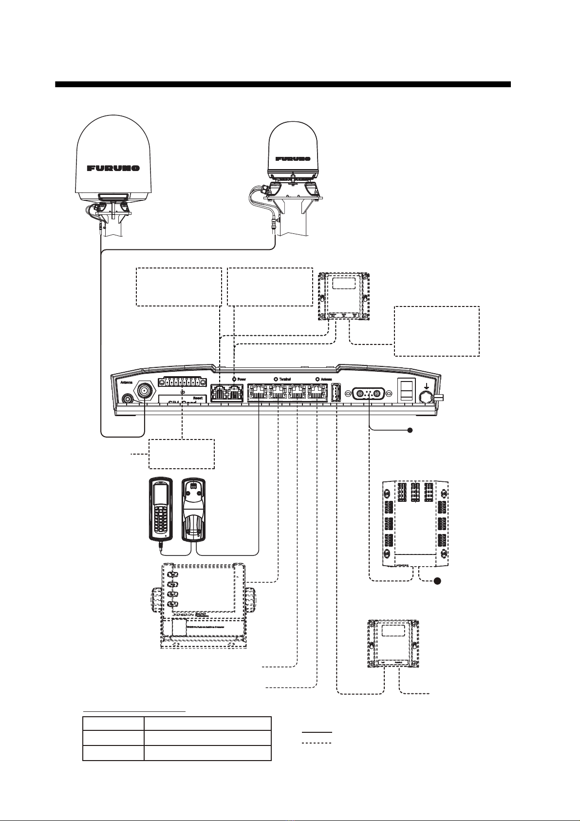
SYSTEM CONFIGURATION ..........................................................................................vi
1. INTRODUCTION .......................................................................................................1
1.1 The Safety Voice (Non-SOLAS) System....................................................................... 1
1.1.1 System components .............................................................................................. 1
1.1.2 IP Handset ............................................................................................................. 2
1.1.3 FleetBroadband system (Communication Unit and Antenna Unit) ........................ 2
1.1.4 Alarm Panel ........................................................................................................... 3
1.2 The Safety Voice (Non-SOLAS) Service....................................................................... 4
2. GETTING STARTED.................................................................................................5
2.1 Service Activation.......................................................................................................... 5
2.2 Checking the System .................................................................................................... 5
2.2.1 In IP Handset ......................................................................................................... 5
2.2.2 In Alarm Panel ....................................................................................................... 5
3. USING THE SYSTEM ...............................................................................................6
3.1 Making a Distress Call .................................................................................................. 6
3.2 Making an Urgency Call (32/38/39)............................................................................... 7
3.3 Receiving Distress Calls ............................................................................................... 9
3.4 Displaying Faults......................................................................................................... 10
3.5 General Functions in the Alarm Panel ........................................................................ 11
3.6 Configuring the System for Safety Voice .................................................................... 12
3.7 Testing the Safety Voice (Non-SOLAS) System ......................................................... 12
4. TROUBLESHOOTING ............................................................................................13
4.1 Status Signalling ......................................................................................................... 13
4.1.1 Alarm Panel ......................................................................................................... 13
4.1.2 IP Handset for Safety Voice................................................................................. 13
4.2 Messages for Notification............................................................................................ 14
4.3 Troubleshooting Guide................................................................................................ 15
4.4 Service and Repair...................................................................................................... 17
4.4.1 Repacking for shipment....................................................................................... 17
GLOSSARY ...............................................................................................................AP-1
INDEX.......................................................................................................................... IN-1

v
FOREWORD
A Word to the Owner of FB-3101
Since 1948, FURUNO Electric Company has enjoyed an enviable reputation for innovative and
dependable marine electronics equipment. This dedication to excellence is furthered by our ex-
tensive global network of agents and dealers.
Congratulations on your choice of the FURUNO FB-3101 Alarm Panel. We are confident you will
see why FURUNO has become synonymous with quality and reliability.
Your equipment is designed and constructed to meet the rigorous demands of the marine envi-
ronment. However, no machine can perform its intended function unless installed, operated and
maintained properly. Please carefully read and follow the recommended procedures for operation
and maintenance.
We would appreciate hearing from you, the end-user, about whether we are achieving our purpos-
es.
Thank you for considering and purchasing FURUNO equipment.

vi
SYSTEM CONFIGURATION
FELCOM501
Antenna Unit
FB-1501
FELCOM251
Antenna Unit
FB-1251
: Standard supply
: Optional or local supply
Environmental category
Units Category
Antenna Unit Exposed to the weather
Other Units Protected from the weather
AC/DC Power
Supply Unit
406080A-FUR-001
100-240V AC
12-24V DC
IP Handset
FB-8001
Alarm Panel
FB-3101
Network Equipment, IP Handset
GS Facsimile
or
Analog Telephone
GS Facsimile
or
Analog Telephone
GS Facsimile
or
Analog Telephone
(
Up to 4 connections
)
External Alarm
Communication Unit
FB-2001
Relay
AY34001
Cradle
PC
USB-RS232C
Converter
FB-3003
Telport Extender
FB-3002

1
1. INTRODUCTION
This chapter introduces the Safety Voice (Non-SOLAS) and gives an overview of the system and
services. It has the following sections:
• The Safety Voice (Non-SOLAS) system
• The Safety Voice (Non-SOLAS) service
1.1 The Safety Voice (Non-SOLAS) System
The Safety Voice (Non-SOLAS) system is primarily used for Distress and Urgency calls using the
FleetBroadband service. The Alarm Panel is used together with a FELCOM251 or FELCOM501
FleetBroadband system and an IP Handset designated for Distress use.
1.1.1 System components
The system includes the following system components:
• Alarm Panel (FB-3101)
• IP Handset (FB-8001)
• Communication Unit (FB-2001)
• Antenna Unit (FB-1251 or FB-1501)
The system components are briefly described in the following sections. Apart from the above
equipment your system may include additional handsets, routers etc.
Instructions on how to assemble the system are found in the Installation Manual (IMC-57060) and
information on wiring.
FELCOM251/501 system
Communication
Unit
Anntena Unit
Optional
Non-Safety
Voice Handset(s)
Alarm Panel
IP Handset
designated for
Safety Voice calls

1. INTRODUCTION
2
1.1.2 IP Handset
The IP Handset is used in the Safety Voice system to make Distress calls
initiated by the Alarm Panel.
When the IP Handset is designated for Safety Voice by the Communication
Unit, the top of the display shows .
When the FB Distress button on the Alarm Panel is pressed, the IP Hand-
set for Safety Voice rings. To be automatically put through to the nearest
Maritime Rescue Coordination Centre (MRCC) do the following:
If the handset is in the cradle: take the handset off the cradle, then speak.
If the handset is not in the cradle: press , then speak.
An IP Handsets which is designated for Safety Voice is also able to function as a normal IP Hand-
set.
Additional IP Handsets may be used for normal voice communication (non-Distress).
1.1.3 FleetBroadband system (Communication Unit and Antenna
Unit)
The FleetBroadband system is a maritime broadband sys-
tem, providing simultaneous high-speed data and voice
communication via satellite.
In the Safety Voice (Non-SOLAS) system, you can enable
the use of priority calling for emergency use in the Commu-
nication Unit. This is done using the built-in web interface,
where you also designate a specific IP Handset for Safety
Voice.
To use the Safety Voice (Non-SOLAS) system you must
connect an IP Handset to the LAN interface and designate
it for Safety Voice. You must also connect an Alarm Panel
to activate Distress calls.

1. INTRODUCTION
3
1.1.4 Alarm Panel
The Alarm Panel is used for initiating Distress calls with the associated IP Handset for Safety
Voice and for indicating incoming Distress or Urgency calls. The Alarm Panel must be placed
close to the IP Handset for Safety Voice.
The buttons and display text in the Alarm Panel are described below.
Buttons:
Display:
No. Control Name Description
1 Test Used for testing the Alarm Panel (buttons, light and sound).
2 Mute Mutes the sound from the buzzer in the Alarm Panel until a
new event activates the buzzer again.
3DimIncreases the light in the display.
4DimDims the light in the display.
5 FB Distress Initiates a Distress call to the nearest Maritime Rescue Co-
ordination Centre (MRCC).
No. Control Name Description
aFB Shows that the Alarm Panel is connected and associated
with the FleetBroadband system (See section 2.2.2).
b Distress Shows that there is a Distress call - either incoming or out-
going.
c Fault Shows that there is a fault in the system. This can be a net-
work problem, a fault in the equipment or wrong configura-
tion.
d Test Shows that there is a Distress test in progress (Distress test
is activated from the IP Handset).
abcd
FB Distress Fault Tes t

1. INTRODUCTION
4
Buzzer:
The Alarm Panel also has a buzzer, which sounds when there is a Distress call or a fault. For the
behavior of the buzzer, see "Buzzer" on page 3-12.
1.2 The Safety Voice (Non-SOLAS) Service
The Inmarsat Safety Voice (Non-SOLAS) service uses FleetBroadband to provide priority call ac-
cess - interrupting all non-distress calls as soon as the red distress button is pushed.
When the red distress button on the Alarm Panel is pushed during an emergency, the service will
interrupt any ongoing non-distress calls - ship to shore or shore to ship. The emergency caller is
then connected to an operator at one of three Maritime Rescue Co-ordination Centers (MRCCs)
strategically located around the globe.
For further details on the Inmarsat services, see inmarsat.com.

5
2. GETTING STARTED
This chapter describes how to make sure the system is ready for making a call. For information
on how to install the system, insert SIM card and connect cables, refer to the Installation Manual
for FELCOM251/FELCOM501 (IMC-57060).
This chapter has the following sections:
• Service activation
• Checking the system
2.1 Service Activation
Before you can use your Safety Voice (Non-SOLAS) system, you must make an airtime subscrip-
tion with your airtime provider and acquire a SIM card for your Communication Unit. The airtime
subscription must include the supplementary services Safety Voice (eMLPP) and Call Waiting.
The Communication Unit can only access the satellite network and use the Safety Voice service
when the right type of SIM card is installed. For information on how to insert the SIM card, refer to
the Installation Manual (IMC-57060) for the FELCOM251/FELCOM501.
2.2 Checking the System
Note: Before you can use the Safety Voice functions, the system must be configured for Safety
Voice. To configure your system for Safety Voice, consult your dealer.
When the system is powered, you can check that it is ready by looking at the display of the IP
Handset and the Alarm Panel.
2.2.1 In IP Handset
Check that the top of the IP Handset display shows .
This symbol indicates that the IP Handset is designated for Safety Voice by the connected Com-
munication Unit.
When the display shows , the system is ready to make a call.
2.2.2 In Alarm Panel
Check that the display of the Alarm Panel shows "FB " (the dot after FB is flashing during startup
until the system is ready for use). This indicates that the Alarm Panel is connected and associated
with a Communication Unit.
Check that the display does not show "Fault".

6
3. USING THE SYSTEM
This chapter describes how to make Distress and Urgency calls and explains the functions of the
Alarm Panel.
Note: This manual only describes functions related to Safety Voice. For information on other func-
tions of the IP Handset and/or the FleetBroadband system see the Operator’s Manual (OME-
57050) for FELCOM251/FELCOM501.
This chapter has the following sections:
• Making a Distress call
• Making an Urgency call
• Receiving Distress calls
• Displaying faults
• General functions in the Alarm Panel
• Configuring the system for Safety Voice
• Testing the Safety Voice (Non-SOLAS) system
3.1 Making a Distress Call
Before you can make a Distress call, the system must be configured for Safety Voice and ready
for use. To configure your system for Safety Voice, consult your dealer.
The system is ready for use when:
• the IP Handset display shows (designated for Safety Voice) and (ready for making calls),
and
• the Alarm panel shows "FB " (connected to Communication Unit).
To make a Distress call, do as follows:
1. On the Alarm Panel, lift the cover for the red FB Distress button.
2. Push and hold the red FB Distress button for 6 seconds, until the buzzer changes to a longer
tone. Then release the button.

3. USING THE SYSTEM
7
3. When the IP Handset for Safety Voice rings, pick up the handset and
accept the call. You are now put through to the nearest MRCC. Follow
the procedure for Safety Voice calls, see "VOICE DISTRESS
CALLS" on page iii. Any ongoing calls with lower priority are automati-
cally disconnected. During the Distress call the display in the IP Hand-
set for Safety Voice and in the Alarm Panel shows "Distress".
3.2 Making an Urgency Call (32/38/39)
The following short codes are available for urgency calls:
• 32: Urgency Medical Advice
• 38: Urgency Medical Assistance
• 39: Urgency Maritime Assistance
Note 1: Urgency calling is an INMARSAT service and is not GMDSS compliant.
Note 2: Urgency calling requires a Safety Voice contract, available through your service provider.
Note 3: You can only make an urgency call from the Safety Voice Handset. The Safety Voice
Handset has the icon in its status bar.
There are two methods to place the emergency call:
• Input a number to call.
• Call at the call [Rescue Call] menu.
When your call is answered, proceed with the normal procedure for urgency calls and provide the
information needed to assist you.
How to input a number
1. Remove the IP Handset from the cradle, and enter the number from the main screen:
2. Press the key or press the Enter key to send the call.
How to call from the [Rescue Call] menu
1. At the main screen, press the key or the 1to #key.
The [Call] screen appears.

3. USING THE SYSTEM
8
2. Press the key to open the sub-menu.
3. Press or to select the [Rescue Call] menu, then press the Enter key.
If your IP Handset is not a Safety Voice Handset, the following menu is not displayed. The
Safety Voice Handset has the icon in its status bar.
4. Press or to select [Medical Advice], [Medical Assist], or [Maritime Assist] menu, then
press the Enter key.
5. Press to select the [Call (32)], [Call (32)], or [Call (39)] menu.
For [Medical Advice] For [Medical Assist] For [Maritime Assist]

3. USING THE SYSTEM
9
3.3 Receiving Distress Calls
Incoming calls with Distress priority will cause the IP Handset for Safety Voice to ring, if it is not
engaged in a call. The display in the IP Handset shows "Distress". Pick up the handset and accept
the call.
If you are already engaged in a Distress call when receiving an incoming Distress call, you will
hear a Call Waiting tone and you can accept or ignore the second call.
If there was an ongoing lower-priority call, you will hear a tone before the first call is terminated
and the Distress call is put through.
When an incoming call with Distress priority is ringing, the Distress indicator in the Alarm Panel
flashes. When the call is established, the indicator lights constantly until the call is terminated.

3. USING THE SYSTEM
10
3.4 Displaying Faults
If there is a fault in the connected equipment or network, the buzzer in the Alarm Panel sounds
and the display of the Alarm Panel shows "Fault".
Note: The Fault indicator is also lit if Safety Voice is disabled in the connected Communication
Unit.
If the Alarm Panel loses connection to the Communication Unit, the dot after FB disappears and
"FB" and "Fault" are flashing.
If the Fault indicator is shown, you can check the list of active events in the IP Handset as follows:
1. From the IP Handset, press the Enter key to open the main
menu.
2. Select [Notifications].
If there are more than one event occurred in the IP Handset or
Communication Unit, the display shows a list. Select an event
in the list to see details.
You can also see a list of active events and an event log in the built-
in web interface of the Communication Unit. For details, see the Op-
erator’s Manual (OME-57050) for your FELCOM251/FELCOM501.

3. USING THE SYSTEM
11
3.5 General Functions in the Alarm Panel
Buzzer
The Alarm Panel has a buzzer, which has the following behaviour:
Buttons
Apart from the FB Distress button, the front panel has four other buttons: Test, Mute, Dim and
Dim . The functions of all the buttons are described in the following sections.
FB Distress button
For how to make a Distress call, see section 3.1. The behavior of the button (for Distress as
well as Distress test) is as follows:
Testing the Alarm Panel
Note: This test only verifies the function of the Alarm Panel itself, not of any connected equipment
or the total system. To test this function, consult your dealer.
To test the light and sound indicators in the Safety Voice (Non-SOLAS), do as follows:
1. Push and hold the Test button .
Verify that the FB Distress button and all light indicators are flashing.
2. While holding the Test button, push and hold any other button, including the FB Distress but-
ton.
The buzzer starts to sound intermittently with increasing strength to indicate that the pushed
button and the buzzer is working.
Muting the alarm sound
To mute the alarm sound while it is on, press the Mute button .
Note: Alarm sound is muted until it is activated by a new event.
Event Behaviour
FB Distress button is pressed. Buzzer sounds intermittently until the Distress
function is activated, then with a longer tone (1
second) followed by silence.
Incoming Distress call ringing. Buzzer sounds intermittently until the call an-
swered.
A fault has occurred. Buzzer sounds with two beeps - pause - two beeps
- pause etc. until the problem has been solved or
the Mute button is pressed.
Distress call has been established. Buzzer is silent until a new event causes it to
sound.
Distress call is cleared.
Mute button is pressed.
Event Behaviour
FB Distress button is pressed. Button light flashes.
Distress call is being established
(dialling).
Button lights constantly.
Distress call has been established. Button lights, but is briefly off every 20 seconds.
Distress call is cleared. Button light is off.

3. USING THE SYSTEM
12
Adjusting the light
To increase the light intensity, press and hold the Dimbutton .
To decrease the light intensity, press and hold the Dimbutton .
To go directly to full light intensity, press both Dim buttons at the same time.
Note: The light always goes to full intensity if there is an event such as a Distress message, a fault
or the Test button is pressed.
You can always use the Dim buttons to dim the light again if you want to.
3.6 Configuring the System for Safety Voice
To configure the system for Safety Voice, consult your local dealer.
3.7 Testing the Safety Voice (Non-SOLAS) System
Apart from checking the displays of the Alarm Panel and the IP Handset as described in the pre-
vious section and testing the Alarm Panel itself as described in "Testing the Alarm Panel" on
page 11, a qualified technician can only test the Distress function for the total system.
To test the Distress function, consult your dealer.
Table of contents
Other Furuno Security System manuals

Furuno
Furuno FELCOM16 User manual

Furuno
Furuno IC-307 User manual

Furuno
Furuno BR-1000 User manual

Furuno
Furuno felcom15 User manual

Furuno
Furuno BR-500 User manual

Furuno
Furuno IC-350 User manual

Furuno
Furuno BR-500 User manual

Furuno
Furuno BR-500 User manual

Furuno
Furuno BR-1000 User manual

Furuno
Furuno SSAS User manual