Nice HSMO - HSA1 User manual

EN-Operation instructions
IT -Istruzioni per l’uso
FR -Mode d’emploi
ES -Instrucciones para el uso
DE-Bedienungsanweisungen
PL -Instrukcje obsługi
NL -Gebruiksaanwijzing
Nice HSMO - HSA1
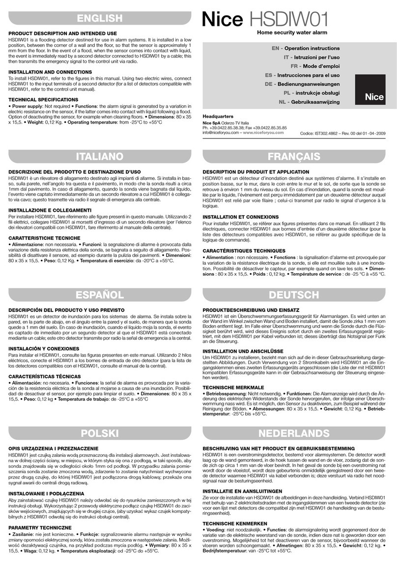
Home security Teleservice


English – 1
EN
1 – SPECIAL WARNINGS
• For personal safety, it is important to observe these instructions, which must be
kept in a safe location for future consultation.
• This manual contains important provisions for installation safety; incorrect installa-
tion procedures may lead to serious hazards.
• Partial reading of these instructions will not enable users to fully exploit the product
features.
•Caution! – Nice S.p.a. declines all liability for faults caused by incorrect installation,
incorrect use or operation failure of the product and relative software.
2 – PRODUCT DESCRIPTION
–The telephone modem HSMO and relative management software “Teleservice”
enables the remote management (teleservice) of the alarm control panels in the sys-
tem Nice Home Security. It is designed exclusively for indoor use (environmental
class 2). Any use other than as specified in this manual is to be considered improper
and is strictly prohibited.
– The HSA1 connection cable and relative management software “Teleservice”
enables the direct connection between a Personal Computer and alarm control pan-
els in the system Nice Home Security.
For correct operation, HSMO must be connected to the electrical mains (230 V), the
fixed telephone network, and a PC, with the relative cables supplied.
It can also run in the event of a power failure by means of a rechargeable backup lead
battery of 6V and 1.2 Ah (not supplied).
To enable use of the teleservice function, a PSTN telephone line is required, as well
as a Personal Computer with the operating system Windows 98 XP or Vista, with
USB port and Cd-Rom drive required for installation.
HSMO features two operating modes: “OFF-LINE” and “ON-LINE”:
- OFF-LINE: modem connected to the PSTN telephone line without connection
to the PC. The modem answers calls automatically, and downloads and memorises
the data sent by the control panel: the memory has a capacity to store data of
approx. 8-10 control panels. When the “DATA” led is lit, this means that there are
data to be downloaded from the memory, using the “Teleservice” software.
- ON-LINE: modem connected to the PSTN telephone line with connection to the
PC and software duly launched. System data can be downloaded directly from the
control panel (this operation lasts a few minutes) or the user can interact directly
with the control panel by means of the “Remote Console” mode.
Caution! – The modem cannot make calls sent to the control panels; it can only
answer incoming calls from the control panels.
With the HSA1 cable connected to the PC, the same assistance operations can be
ENGLISH
Original instructions

2– English
EN
performed directly on the control panel as those performed remotely using the
HSMO modem. This enables programming of the control panel via the PC, storage of
data, reading of the events memory etc.
Voice messages cannot be recorded as the microphone incorporated in the control
panel would be required.
3 – INSTALLATION
3.1 - HSMO
Warnings
• Caution! – The product is subject to hazardous voltage levels. Before remov-
ing the protection cover, ensure that the power plug is disconnected from the
mains.
•All electrical connections must be made with the unit disconnected from the
mains power supply.
• Installation and maintenance must be performed by qualified technical personnel in
observance of these instructions and local standards and legislation.
• Never break or perforate the housing.
To install HSMO, simply connect it to a standard mains power socket (230 V).
If the backup battery is to be installed, this must be performed before connecting
HSMO to the electrical mains, as follows:
01. Remove the protection cover using a screwdriver to lever it off, at the point
shown in fig. 2 - phase A;
02. Remove the screw shown in fig. 2 - phase B;
03. Delicately remove the electronic board and set aside as shown in fig. 2 -
phase C;
04. Remove the o-ring (fig. 2 - phase D);
05. Connect the 2 wires (red and black) to the respective poles of the backup bat-
tery, as shown in fig. 2 - phase E: red = +, black = -
06. Replace the battery in its seat and secure by means of the o-ring (fig. 2 -
phase F);
07. Delicately insert the electronic board into its seat (fig. 2 - phase F);
08. Secure the electronic board using the relative screw (fig. 2 - phase G and H);
09. Refit the protection cover, taking care that it clicks fully into place (fig. 2 -
phase I).
Note – If the HSMO modem is not used for prolonged intervals and remains discon-
nected from the electrical mains, the backup battery should be disconnected and
removed.
To complete installation, connect HSMO to the telephone socket using the cable
supplied (fig. 1). Note – If a broadband connection is present, the cable must be
connected to the telephone outlet (after the broadband filter).
CAUTION – The connection between HSMO and the PC must be made exclu-
sively at the time as envisaged in the software installation sequence (see para-

English – 3
EN
graph 3.3). If the connection is made in advance, this may cause incorrect or
failed installation of the drivers.
3.2 - HSA1
To install HSA1, simply connect it to the control panel socket and USB port of the PC
as shown in fig. 3.
3.3 - “Teleservice” Software
Caution – To use the remote management function, the “Teleservice” software
must be installed on a PC connected to the modem. Installation of the software
implies acceptance of the clauses in the User License.
The “Teleservice” software can be used in combination with the HSMO modem or
directly in combination with the control panel via the specific adaptor cable HSA1. In
the latter case, at point 03 of the installation procedure, use the HSA1 cable to con-
nect the control panel to the PC.
To install the Teleservice software on the PC, proceed as follows:
01. Insert the software CD-ROM in the PC drive and wait for the main menu to be
displayed; if this is not started automatically, open “My Computer” and double
click on the CD-ROM icon and then on the file “Index.htm”.
02. Select the required language, followed by “Installation” and follow the instruc-
tions on screen. At the end of installation, an application shortcut is created
directly on the desktop.
03. Only at this point, power up the HSMO and connect it to the USB port of the PC
using the relative cable.
If the drivers have not already been installed, also from other applications, the
LED
220 V
Battery
Data
Connection
TX Data
RX Data
DESCRIPTION
Mains power ON
Power failure
Battery discharged
Battery OK
Data present in memory, downloaded from
systems
No system data present in memory
Telephone connection in progress
No telephone connection in progress
Data traffic present on USB
Teleservice software not active or USB cable
not inserted
Data traffic present on USB
Teleservice software not active or USB cable
not inserted
STATUS
on
off
on
off
on
off
on
off
flashing
off
flashing
off
Description of led indicators on the HSMO modem

4– English
EN
connection of HSMO to the PC automatically starts up the “Add Hardware wiz-
ard” used to install the drivers required for operation of the USB connection
between the PC and modem.
04. In the window “Add Hardware wizard” select “Install from a list or specific
path” to find the files (type FTDI) required; this runs the search for the drivers
also on the CD-ROM. Note – Do not run the search for drivers on the Internet,
even if connected.
05. Confirm installation of the drivers FTDI.
06. The driver installation procedure may be performed twice as both the drivers for
the USB port and those of the serial port need to be installed.
07. At this point, software installation is complete; the application can be started up
at any time by double clicking on the icon “NiceHsmo” on the desktop or in the
Programs folder.
Caution – The cable between HSMO and the PC must always be connected to the
same USB port of the PC; otherwise the USB drivers may need to be installed again.
On program start-up, if a message similar to “DNS installation failed” is displayed,
open the folder “Private” on the CD-ROM, double click on the application
“MDAC_TYP.EXE” and follow the instructions on screen.
4 – TELESERVICE
Alarm control panels can be controlled remotely via the fixed telephone line by means
of the modem HSMO and the software “Teleservice”: it enables download of all set-
tings present and the log of events of the control panel, for direct intervention as
required via a specific control panel, just as if the installer were physically present in
front of the control panel. This enables an analysis and solution of any problems with-
out the need for on-site inspections.
Real operation tests cannot be performed via the remote connection (neither the sys-
tem or sirens can be activated), but it is possible to perform and display control pan-
el operation tests.
In OFF-LINE mode: the remote connection, must be activated explicitly by the
user, pressing the key for at least 5 seconds; the control panel immediately calls
the specifically memorised telephone number, connects to the modem and down-
loads all onboard data. This operation does not require connection of the modem to
the PC.
In ON-LINE mode: to act directly on the control panel, the telephone connection
must be activated and the software Teleservice must be running on the PC.
To guarantee safety, the user can check all operations in progress on the display; in
any event avoid any interventions during the connection to prevent possible conflict.
Note – All operations performed are recorded in the “event log”.
After one minute of continuous inactivity, the remote connection terminates automat-
ically and the control panel returns to its initial status before the connection.
The control panel can be configured to enable autonomous connection to the
modem following a specific telephone call, without the need for manual activation of
the procedure by the user.
English – 5
EN
To do this, a special access code must be entered: see the “Telemanagement”
menu. To start up the operation, proceed as follows:
01. Make the call to the control panel and listen to the guided reply message;
02. Enter the access code followed by # to start up teleservice;
03. Terminate the call. At this point, the control panel calls the telephone number
envisaged for the modem connection.
Caution! – As this type of operation is delicate and involves a significant
amount of responsibility, the system must be switched off during connection.
Nice declines all liability for the above and advises the user and installer to
stipulate an agreement in writing regarding use of the telemanagement func-
tion in absence of the user.
Important – The user can disable this function at any time by simply deleting the
installer access code.
4.1 – Programming the control panel for teleservice
The menu “Telemanagement” is present on the menu (advanced settings; without
voice guide) to enable the configuration of all parameters related to the teleservice
function:
(*) In some particular cases, for example to locate specific programming or configu-
ration problems, the Nice Service Centre may need to perform some operations
directly in teleservice mode: the installer must contact the relative service centre to
agree upon the remote intervention procedure and must be available on site. In this
way the service centre can supply the telephone number corresponding to the direct
line of the specific modem. The number must be entered in SERV. CENTRE NUM-
BER and subsequently, to activate the call, the item CALL SERV. CENTRE must be
confirmed.
ACCESS CODE
INSTALLER NAME
INSTAL. NUMBER
SERV. CENTRE
NUMBER
CALL SERV. CENTRE
PERSONAL DATA:
NAME
SURNAME
ADDRESS
TOWN
PHONE
Enables the entry of the specific access code for teleservice when
activated by a remote call. The code must comprise 4 digits and
must be different from the User code and Installer code.
Enables entry of the installer name (as a note)
Enables entry of the telephone number for the call to the
modem.
Permette di inserire il numero di telefono del centro assistenza
di Nice (*)
Enables activation of the call to the Nice service centre (*)
Enables entry of the personal data of the system owner; these
data are particularly useful when the control panel downloads
them automatically to the modem, to enable identification of
the source.
Note – These data are hidden if teleservice is via the Nice ser-
vice centre; in this way the user data are not recognised.
Telemanagement menu

6– English
EN
Caution! – Nice S.p.a offers this service to the installer exclusively for collabo-
ration purposes, and does not accept any liability with regard to the installer or
user.
4.2 - Using the “teleservice” software
To start up the software “Teleservice” double click on the icon “NiceHsmo” on the
desktop or in the Programs folder; the following window is displayed to enable selec-
tion of the language used by the software:
On selection of the language, the main window is displayed:
– the upper section contains the buttons for the main software functions;
– the lower section contains the data indicating the software status and some infor-
mation useful for solving any connection problems; the COM port number used for
the connection is also displayed.
On initial start-upon of the software, all free COM ports not used for other purposes
are tested by the system, until the port used by the USB driver is found. This search
may last a few seconds, if the COM port number is rather high (the example in the fig-

English – 7
EN
ure refers to number 26). Note – On subsequent start-ups of the software, the sys-
tem first tests the port previously used.
At this point, the system searches for the type of device connected to a control pan-
el (connected directly with the HSA01 cable) or to the HSMO modem.
The indicators in the figure below change colour according to the type of connection
present:
- In the case of a direct connection to a control panel, the “Control panel” indicator is
green and the “HSMO” indicator is red;
- In the case of a connection via modem, both indicators are green.
4.2.1 - HSMO Setup
This window enables the selection of the type of telephone connection used:
- Select “dedicated line” if only the modem is present on the telephone line; in this
case, the modem answers on the first ring.
- Select “traditional line” if the line is also used for normal phone calls or faxes. In
this case, the modem requires a repeated call to answer. The first call enables the
modem to answer the second call, which must be made within the set waiting time
(16 seconds set as default).

8– English
EN
The control panels adapt automatically to the type of line set and, if necessary, auto-
matically make the double call.
4.2.2 - Data reading
This window enables the user to download all data “parked” in the modem; these
data can be viewed in the next window “Technical sheet” (see paragraph 4.2.3).
4.2.3 - Technical sheet
In this window, on selection of one or all systems present, a second window “Tech-
nical sheet” is displayed, showing the details of the selected system. To do this,
select the various menus present in the upper section of the screen:
• SYSTEM: displays the main data of the control panel and personal data of the
user;
• PHONE BOOK – MESSAGES – TOOLS – SETTINGS – DIGIT. PROT.– LOG: dis-
play the data entered in the respective menus of the control panel;
• PRINT: enables printout on paper of the system data. This enables selection of the
type of data to print out on the specific sheet.

English – 9
EN
4.2.4 - Connection to the control panel
This window enables the user to download updated system data (system data
download) or to activate the “remote console”, only if the connection to a control
panel is present (direct or via modem).
If the “remote console” is activated, a window is displayed (see figure below) which
shows the contents of the control panel display. In this case the user can use the
keypad below to program settings in the same way as acting directly on the control
panel.
Note – If the remote connection is used, voice messages cannot be recorded and
the total deletion function cannot be used.

10 – English
EN
To increase or move peripherals, the work must be performed by a person physical-
ly present on site to enable completion of the practical installation procedures, bat-
tery insertion etc.
5 – MAINTENANCE
HSMO does not require special maintenance. The device is fitted with an internal
rechargeable buffer battery which is activated in the event of a power failure. The aver-
age lifetime of this battery is 4-7 years (decisive factors include environmental temper-
ature, frequency and intensity of use). It must be replaced at the end of this period.
Otherwise a practical test of system duration must be performed: disconnect the
mains power supply and check how long afterwards the low battery signal is activat-
ed. Replace the battery when the time is half that of the normal value or less than the
required service time.
If HSMO remains unused and not mains-powered for a period of over 2 days, at least
one internal battery pole must be disconnected and the unit must be stored in a cool
and dry location.
6 – DISPOSAL
As in installation, also at the end of product lifetime, the scrapping operations must
be performed by qualified personnel.
This product comprises various types of materials, some of which may be recycled
and others must be disposed of; seek information of the methods of recycling or dis-
posal as envisaged by local legislation for this product category.
Some product parts may contain pollutant or hazardous substances; if disposed of
these could harm the environment and personal health.
As indicated by the symbol in the figure, disposal of this product in
domestic waste is strictly prohibited.
Separate the waste into categories for disposal, according to the
methods envisaged by current legislation in your area, or return
the product to the retailer when purchasing a new version. Local
legislation may envisage serious fines in the event of abusive dis-
posal of this product.

English – 11
EN
CAUTION! – This product contains a lead battery (Pb)
Disposal of batteries according to current legislation is compulsory. In the
event of product disposal, the internal battery must be removed and deposited
in the special containers provided by the distribution network.
In the event of leaks of substances from batteries, protect the hands with suit-
able gloves to avoid injury.
7 – TECHNICAL SPECIFICATIONS
WARNINGS: • All technical specifications stated in this section refer to an ambient
temperature of 20°C (± 5°C). • Nice S.p.a. reserves the right to apply modifications
to products at any time when deemed necessary, maintaining the same intended use
and functionality.
HSMO
■Power supply: 230 Vac, 50/60 Hz
■Absorbed power: < 0.9 W on stand by; < 4 W during battery recharging
■Backup power supply: with rechargeable lead battery 6 V 1.2 Ah (optional)
■Autonomy in event of power failure: over 3 days according to intensity of use
■PSTN interface: RJ45 connector
■USB interface: type B connector, USB compatible rev.1.1.
■Protection rating: IP40 (with container intact)
■Operating temperature from -10° to +40 °C
■Dimensions / weight: 162 mm x 120 mm x 83 mm (cables excluded) / 0.7 kg
HSA1
■USB interface: type B connector, USB compatible rev.1.1.
■Protection rating: IP40 (with container intact)
■Operating temperature from -10° to +40 °C
■Cable length: 1.7 m

12 – English
EN
CE DECLARATION OF CONFORMITY
Note - The contents of this declaration correspond to declarations in the official document deposited at the registered offices
of Nice S.p.a. and in particular to the last revision available before printing this manual. The text herein has been re-edited for
editorial purposes.
Number: 327/HSMO Revision: 0
The undersigned, Luigi Paro, in the role of Managing Director, declares under his sole responsibility, that
the product:
Manufacturer’s Name: NICE s.p.a.
Address: Via Pezza Alta 13, Z.I. Rustignè, 31046 Oderzo (TV) Italy
Type: Telephone modem
Models: HSMO
Accessories:
Conforms to the essential requirements stated in article 3 of the following EC directive, for the intended
use of products:
• 1999/5/EC; DIRECTIVE 1999/5/EC OF THE EUROPEAN PARLIAMENT AND COUNCIL of 9 March
1999 regarding radio equipment and telecommunications terminal equipment and the mutual recog-
nition of their conformity
According to the following harmonised standards: electrical safety: EN 60950-1:2006;
Electromagnetic compatibility: EN 61000-6-2:2005, EN 61000-6-3:2007
telecommunication terminal equipment: ES 203 021-1 V. 2.1.1:2005,
ES 203 021-2 V. 2.1.2:2006, ES 203 021-3 V. 2.1.2:2006
The product also conforms to the requirements of the following EC directives:
• 2004/108/EEC DIRECTIVE 2004/108/EEC OF THE EUROPEAN PARLIAMENT AND COUNCIL of 15
December 2004 regarding the approximation of member state legislation related to electromagnetic
compatibility, repealing directive 89/336/EEC
According to the following harmonised standards: EN 50130-4:1995+A1:1995+A2:1995
Oderzo, 04.08.09 Luigi Paro (Managing Director)
CE DECLARATION OF CONFORMITY
Note - The contents of this declaration correspond to declarations in the official document deposited at the registered offices
of Nice S.p.a. and in particular to the last revision available before printing this manual. The text herein has been re-edited for
editorial purposes.
Number: 327/HSA1 Revision: 0
The undersigned, Luigi Paro, in the role of Managing Director, declares under his sole responsibility, that
the product:
Manufacturer’s Name: NICE s.p.a.
Address: Via Pezza Alta 13, Z.I. Rustignè, 31046 Oderzo (TV) Italy
Type: Control interface
Models: HSA1
Accessories:
Conform with the requirements of the following EC directives:
• 2004/108/EEC DIRECTIVE 2004/108/EEC OF THE EUROPEAN PARLIAMENT AND COUNCIL of 15
December 2004 regarding the approximation of member state legislation related to electromagnetic
compatibility, repealing directive 89/336/EEC
According to the following harmonised standards: EN 55024:1998+A1:2001+A2:2003;
EN 55022:2006+A1:2007, EN 50130-4:1995+A1:1995+A2:1995
Oderzo, 06.10.09 Luigi Paro (Managing Director)

1 – AVVERTENZE SPECIFICHE
• Per la sicurezza delle persone è importante rispettare queste istruzioni e conservar-
le per poterle consultare in futuro.
• Il presente manuale contiene importanti disposizioni per la sicurezza dell'installazio-
ne, installazioni non corrette possono creare gravi situazioni di pericolo.
• Una lettura solo parziale di queste istruzioni non permetterà di sfruttare al meglio le
caratteristiche del prodotto.
•Attenzione! – Nice S.p.a. declina ogni responsabilità conseguente ad un’errata in-
stallazione, un errato utilizzo oppure ad un mancato funzionamento del prodotto e
del relativo software abbinato.
2 – DESCRIZIONE DEI PRODOTTI
–Il modem telefonico HSMO e relativo software di gestione “Teleservice” permette la
gestione a distanza (teleassistenza) delle centrali di allarme del sistema Nice Home
Security. È previsto l’impiego esclusivamente in ambienti interni (classe ambientale 2).
Ogni altro uso, diverso da quanto descritto in questo manuale è improprio e vietato.
–Il cavo di connessione HSA1 ed il relativo software di gestione “Teleservice” per-
mette il collegamento diretto tra un Personal Computer e le centrali di allarme del
sistema Nice Home Security.
HSMO, per funzionare deve essere collegato alla corrente elettrica di rete (230 V), alla
rete telefonica fissa e ad un Personal Computer, con gli appositi cavi in dotazione.
Può funzionare anche in assenza di alimentazione elettrica con l’utilizzo di una batte-
ria di backup (non in dotazione) di tipo ricaricabile al piombo da 6 V e 1,2 Ah.
Per utilizzare la teleassistenza è necessario disporre di una linea telefonica PSTN e di
un Personal Computer con sistema Windows 98 XP oppure Vista, con porta USB e
con lettore Cd-Rom necessario per l’installazione.
HSMO dispone di due modalità di funzionamento “OFF-LINE” e “ON-LINE”:
- OFF-LINE: modem collegato alla linea telefonica PSTN senza collegamento al
PC. Il modem risponde automaticamente alle chiamate, scarica e memorizza i dati
provenienti dalla centrale: la sua memoria ha una capacità di memorizzare i dati di
circa 8/10 centrali. Quando il led “DATA” è acceso, indica che nella memoria sono
presenti dei dati da scaricare, utilizzando il software “Teleservice”.
- ON-LINE: modem collegato alla linea telefonica PSTN con collegamento al PC e
software avviato. È possibile scaricare i dati dell’impianto direttamente dalla centra-
le (l’operazione dura qualche minuto) oppure interagire direttamente con la centrale
utilizzando la modalità “Consolle Remota”.
Attenzione! – Il modem non può effettuare chiamate telefoniche indirizzate alle cen-
trali; può esclusivamente rispondere alle chiamate entranti provenienti dalle centrali.
ITALIANO
Istruzioni originali
IT
Italiano – 1

2– Italiano
Con il cavo HSA1 collegato al PC, è possibile eseguire direttamente sulla centrale, le
stesse operazioni di assistenza che possono essere eseguite a distanza con l’utilizzo
del modem HSMO. Questo, consente la programmazione della centrale attraverso il
PC, il salvataggio dei dati, la lettura della memoria eventi, ecc.
Non è possibile effettuare la registrazione dei messaggi vocali, perchè è necessario
utilizzare il microfono di bordo della centrale.
3 – INSTALLAZIONE
3.1 - HSMO
Avvertenze
•Attenzione! – Il prodotto è sottoposto a tensione elettrica pericolosa: prima
di togliere il coperchio di protezione, verificare che la spina di alimentazione
sia disinserita dalla rete di alimentazione elettrica.
•Tutti i collegamenti devono essere eseguiti senza la presenza di alimentazio-
ne elettrica.
• L’installazione e la manutenzione devono essere effettuate da personale tecnico qua-
lificato nel rispetto delle presenti istruzioni e delle norme e leggi esistenti sul territorio.
• Non rompere e non forare il contenitore.
Per installare HSMO è sufficiente collegarlo ad una comune presa di corrente elettri-
ca di rete (230 V).
Se si desidera installare la batteria di backup, è necessario eseguire questa opera-
zione prima di collegare HSMO alla corrente elettrica di rete e procedere nel
modo seguente:
01. Togliere il coperchio di protezione utilizzando un cacciavite a taglio per fare leva
nel punto indicato in fig. 2 - fase A;
02. Togliere la vite indicata in fig. 2 - fase B;
03. Estrarre delicatamente la scheda elettronica e porla a lato come mostrato in fig.
2 - fase C;
04. Togliere l’o-ring presente (fig. 2 - fase D);
05. Collegare i 2 cavetti (rosso e nero) ai rispettivi poli della batteria tampone, come
mostrato in fig. 2 - fase E: rosso = +, nero = -
06. Riporre la batteria nella sua sede e bloccarla con l’apposito o-ring (fig. 2 - fase F);
07. Inserire delicatamente la scheda elettronica nella sua sede (fig. 2 - fase F);
08. Bloccare la scheda elettronica con l’apposita vite (fig. 2 - fase G e H);
09. Riposizionare il coperchio di protezione facendo attenzione ad incastrarlo corret-
tamente (fig. 2 - fase I).
Nota – Se il modem HSMO rimane inutilizzato e non collegato alla rete elettrica per
lungo tempo, è opportuno scollegare e rimuovere la batteria di backup.
Per completare l’installazione, collegare HSMO alla presa telefonica con l’apposito
cavo in dotazione (fig. 1). Nota – In presenza della linea ADSL, il cavo deve essere
collegato all‘uscita per il telefono (dopo il filtro ADSL).
ATTENZIONE! – Il collegamento di HSMO al PC, deve essere eseguito esclusi-
vamente nel momento previsto dalla sequenza d’installazione del software

(vedere paragrafo 3.3). Eseguire un collegamento anticipato, può provocare
un’errata o inutile installazione dei driver.
3.2 - HSA1
Per installare HSA1, è sufficiente collegarlo alla presa della centrale e alla presa USB
del PC come mostrato in fig. 3.
3.3 - Software “Teleservice”
Attenzione – Per utilizzare la funzione di telegestione, è richiesta l’installazio-
ne del software “Teleservice” su un PC collegato al modem. L’installazione del
software, implica l’accettazione delle clausole di licenza d’uso.
Il software “Teleservice” può essere usato in abbinamento al modem HSMO oppure
direttamente in abbinamento alla centrale attraverso lo specifico cavo adattatore
HSA1. In questo secondo caso, al punto 03 della procedura d’installazione, usare il
cavo HSA1 per collegare la centrale al PC.
Per installare il software Teleservice nel PC, procedere nel modo seguente:
01. Inserire, nel lettore del PC, il CD-ROM del software ed attendere la visualizzazio-
ne del menu principale; se quest’ultimo non si avvia automaticamente, aprire
“Risorse del Computer” e fare doppio clic prima sull’icona del CD-ROM e poi
sul file “Index.htm”.
02. Scegliere la lingua desiderata, selezionare “Installazione” e seguire le istruzioni
che appaiono a video. Al termine dell’installazione, viene creato direttamente sul
“desktop” un collegamento all’applicativo.
03. Solo a questo punto, dare alimentazione a HSMO e collegarlo alla presa USB
Italiano – 3
IT
LED
220 V
Battery
Data
Connection
TX Data
RX Data
DESCRIZIONE
Presenza rete elettrica
Mancanza rete elettrica
Batteria scarica
Batteria OK
Sono presenti in memoria dati scaricati da
impianti
Non ci sono in memoria dati scaricati da
impianti
Connessione telefonica in corso
Nessuna connessione telefonica in corso
Presenza traffico dati su USB
Software Teleservice non attivo o cavo USB
non inserito
Presenza traffico dati su USB
Software Teleservice non attivo o cavo USB
non inserito
STATO
acceso
spento
acceso
spento
acceso
spento
acceso
spento
lampeggiante
spento
lampeggiante
spento
Descrizione dei led presenti sul modem HSMO

4– Italiano
IT
del PC con l’apposito cavo.
Se i driver non sono già stati installati, anche da altre applicazioni, il collegamen-
to di HSMO al PC provoca l’avvio “dell’Installazione guidata nuovo Hardwa-
re” che serve per installare i driver necessari al funzionamento della connessione
USB tra PC e modem.
04. Nella finestra “Installazione guidata nuovo Hardware” scegliere “Installa da
un elenco o percoso specifico” per trovare i file (tipo FTDI) necessari; in que-
sto modo, viene eseguita la ricerca dei driver anche nel disco CD-ROM. Nota –
Non eseguire la ricerca dei driver in internet anche se si possiede una connes-
sione a quest’ultimo.
05. Confermare l’installazione dei driver FTDI.
06. La procedura d’installazione dei driver potrebbe essere eseguita 2 volte perché
devono essere installati sia i driver della porta USB sia quelli della posta seriale.
07. A questo punto, l’installazione del software è completata; il software, potrà
essere avviato in qualsiasi momento facendo doppio clic sull’icona “NiceHsmo”
presente sul “desktop” oppure nella cartella “programmi”.
Attenzione – Occorre collegare il cavo di collegamento tra HSMO e PC, sempre alla
stessa porta USB del PC; altrimenti, potrebbe essere necessario installare nuova-
mente i driver USB.
Se all’avvio del programma appare un messaggio simile a “Installazione DNS non riu-
scita”, occorre aprire la cartella “Private” presente sul CD-ROM, fare doppio click
sull’applicazione “MDAC_TYP.EXE” e seguire le istruzioni a video.
4 – TELEASSISTENZA
Con il modem HSMO e il software “Teleservice”, attraverso la rete telefonica fissa, è
possibile controllare a distanza la centrale di allarme: è possibile scaricare tutte le
programmazioni presenti e lo storico della memoria eventi della centrale e operare
direttamente su di essa, attraverso un pannello di controllo, esattamente come se
l’installatore fosse fisicamente davanti alla centrale. In questo modo, è possibile ana-
lizzare e risolvere eventuali problemi senza doversi recare sul posto.
Attraverso il collegamento remoto, non è possibile fare prove reali di funzionamento
(non si inserisce e non suonano sirene) ma è possibile effettuare e visualizzare le ope-
razioni di test della centrale.
In modalità OFF-LINE: il collegamento remoto, deve essere esplicitamente atti-
vato dall’utente premendo il tasto per almeno 5 secondi; la centrale chiama
istantanemente il numero telefonico appositamente memorizzato, si collega al
modem e scarica tutti i dati di bordo. Per questa operazione non è necessario che il
modem sia collegato al PC.
In modalità ON-LINE: per operare direttamente sulla centrale è necessario che sia
attivo sia il collegamento telefonico sia che il software Teleservice sia avviato sul PC.
Per garantire la sicurezza, l’utente può controllare sul display tutte le operazioni in
corso; comunque, si consiglia di non intervenire durante il collegamento per evitare
eventuali conflitti. Nota – Tutte le operazioni effettuate vengono registrate nella
“memoria eventi”.

IT
Dopo un minuto continuo d’inattività, il collegamento remoto termina automatica-
mente e la centrale torna allo stato iniziale, prima della connessione.
È possibile configurare la centrale in modo che possa collegarsi autonomamente
al modem a seguito di una specifica chiamata telefonica, senza la necessità dell’atti-
vazione manuale della procedura da parte dell’utente.
Per fare questo, occorre inserire uno specifico codice di accesso: vedere menu
“Telegestione”. Per avviare l’operazione, procedere nel modo seguente:
01. Eseguire la chiamata alla centrale ed ascoltare il messaggio guida di risposta;
02. Digitare il codice di accesso seguito dal tasto #, per avviare la teleassistenza;
03. Terminare la chiamata. A questo punto, la centrale chiama il numero telefonico
previsto per la connessione al modem.
Attenzione! – Poichè questo tipo di intervento presenta delicati aspetti e
responsabilità oggettive, durante il collegamento il sistema deve essere disin-
serito. Nice declina qualsiasi tipo di responsabilità in merito e consiglia l’uten-
te e l’installatore di concordare, in forma scritta, l’utilizzo della telegestione in
assenza dell’utente.
Importante – L’utente può disabilitare questa funzionalità, in qualsiasi momento,
semplicemente cancellando il codice di accesso dell’installatore.
4.1 - Programmazione della centrale per la teleassistenza
Nella Centrale, è presente il menu “Telegestione” (programmazione avanzata; senza
guida vocale) che consente di configurare tutti i parametri necessari alla teleassistenza:
(*) In alcuni casi particolari, ad esempio per la ricerca di particolari problemi di pro-
grammazione o configurazione, può essere necessario che il centro assistenza di Nice
Italiano – 5
CODICE ACCESSO
NOME INSTALL.
NUMERO INSTALL.
NUMERO CEN. ASS.
CHIAMA CEN. ASS.
ANAGRAFICA:
NOME
COGNOME
INDIRIZ.
CITTA’
TELEFONO
Permette di inserire lo specifico codice di accesso per la tele-
assistenza quando questa viene attivata da una chiamata
remota. Il codice deve essere di 4 cifre e diverso dal codice
Utente e codice Installatore.
Permette di inserire il nome dell’installatore (per promemoria)
Permette di inserire il numero di telefono per la chiamata al
modem
Permette di inserire il numero di telefono del centro assistenza
di Nice (*)
Permette di attivare la chiamata al centro assistenza di Nice (*)
Permette di inserire i dati anagrafici del proprietario dell’impian-
to; i dati sono particolarmente utili quando la centrale li scarica
automaticamente sul modem perché ne viene identificata la
provenienza.
Nota – Questi dati non sono “visibili” se la teleassistenza avvie-
ne da parte del centro assistenza Nice; in questo modo i dati
dell’utente non vengono riconosciuti.
Menu Telegestione

effettui direttamente alcune operazioni in teleassistenza: l’installatore deve contattare il
centro assistenza per concordare la modalità dell’intervento remoto e deve rendersi
disponibile con la prorpia presenza sul posto. In questo modo, il centro assistenza può
fornire il numero telefonico corrispondente alla linea diretta del proprio modem. Il
numero deve essere inserito alla voce NUMERO CEN. ASS. e successivamente, per
attivare la chiamata, deve essere confermata la voce CHIAMA CEN. ASS.
Attenzione! – Nice S.p.a offre questo servizio all’installatore esclusivamente
come collaborazione, ma senza alcuna assunzione di responsabilità nei con-
fronti dell’installatore e dell’utente.
4.2 - Utilizzare il software “teleservice”
Per avviare il software “Teleservice” occorre fare doppio clic sull’icona “NiceHsmo”
presente sul “desktop” o nella cartella “programmi”, immediatamente appare la
seguente finestra che consente la scelta della lingua usata dal software:
Dopo la scelta della lingua, appare la finestra principale:
IT
6– Italiano
Table of contents
Languages:
Other Nice Security System manuals

Nice
Nice HSCU1 Technical specifications

Nice
Nice HSDIW01 User manual

Nice
Nice FE Series User manual

Nice
Nice HSSO User manual

Nice
Nice Linear IV200 Series User manual

Nice
Nice MyNice MNS User manual

Nice
Nice HSSOC User manual

Nice
Nice HSSOC User manual

Nice
Nice HSDIW01 User manual

Nice
Nice HSSO1 Technical specifications