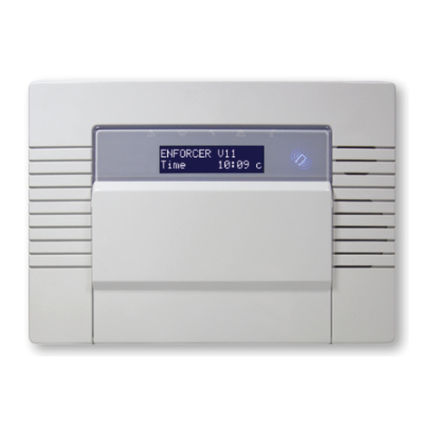
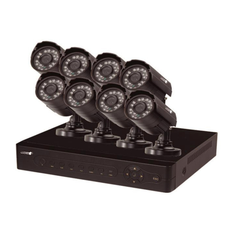
Inhep Digital Security IDS404 User guide


2 IDS404 INSTALLER MANUAL NO. 700-277-02A ISSUED SEPT 2004 VER 1.02
IDS404INSTALLERMANUAL
Summary of Operation
mrasiD/mrA ]#[ +]EDOCRESU[
mrAyawAkciuQ
nwoddloH
]1[
dnoces1rof
mrAyatSkciuQ
nwoddloH
]5[
dnoces1rof
oG&mrAyatSkciuQ
nwoddloH
]6[
dnoces1rof
lenaPybrewsnAdecroF
nwoddloH
]8[
demrasidebtsummetsyS-
cinaP
nwoddloH
]P[
dnoces1rof
eriF
nwoddloH
]F[
dnoces1rof
ycnegremElacideM
nwoddloH
]M[
dnoces1rof
yromeMmralA
nwoddloH
]0[
dnoces1rof
eliforPyatSegnahC ]EDOM[ +]9[ +]REBMUNELIFORP[ +[!!
!
!!]
enoZassapyB [!!
!
!!]+]REBMUNENOZ[
enoZemihCmargorP
nwoddloH
]2[
[+dnoces1rof
]REBMUNENOZ
+[!!
!
!!]
enoZyatSmargorP
nwoddloH
]3[
[+dnoces1rof
]REBMUNENOZ
+[!!
!
!!]
enoZzzuBmargorP
nwoddloH
]4[
[+dnoces1rof
]REBMUNENOZ
+[!!
!
!!]
sutatSelbuorTweiV
nwoddloH
]7[
sseruD ]#[ +]EDOCSSERUD[
41egapeeS-ediuGgnimmargorProF

IDS404 INSTALLER MANUAL NO. 700-277-02A ISSUED SEPT 2004 VER 1.02 3
IDS404INSTALLERMANUAL
Contents
1. Introduction to the IDS404............................................5
1.1 Features...........................................................................5
2. Installation and Wiring ..................................................6
3. End-of-Line Resistors/Tamper per Zone & Zone
Doubling .........................................................................7
4. Zone Expansion .............................................................9
5. Box Tamper Zone ..........................................................9
6. Connecting the Telephone Communicator ................9
7. Telephone Line Integrity Monitoring ........................10
8. Programmable Outputs...............................................10
9. The Key-Switch or Remote Control Unit .................. 11
10. Additional Technical Data ...........................................11
11. Hardware Reset Switch ..............................................13
12. Event Log.....................................................................13
13. Dialler Progress Mode................................................14
14. Download Code ...........................................................14
15. Programming Instructions ..........................................15
15.1 Introduction ....................................................................15
15.2 LocationValues..............................................................15
15.3 Programming the Panel .................................................16
15.4 Program Location Summary..........................................17
16. Trouble Conditions Summary.....................................51

4 IDS404 INSTALLER MANUAL NO. 700-277-02A ISSUED SEPT 2004 VER 1.02
IDS404INSTALLERMANUAL
Figures
Figure 1: Connection Diagram..............................................6
Figure 2: resistors used for Tamper per Zone and Zone
Doubling .................................................................................8
Figure 3: Tamper per Zone Connection ..............................8
Figure 4: Connection for Zone Doubling.............................8
Figure 5: Programmable Output Configuration ..................9
Figure 6: Strobe Output Sequence ...................................31
Figure 7: Fire Detect Output Sequence............................32
Tables
Table 1: Dialler Progress as shown by zone LED’s..........14
Table 2: Value represented by each zone indicator.........15
Table 3: Binary Representation..........................................16
Table 4: Location/ Zone Defaults........................................18
Table 5: Programmable Zone Types...................................19
Table 6: Output Options......................................................29
Table 7: Location default values ........................................29
Table 8: Standard Contact ID reporting codes .................36
Table 9: Alarm reporting codes...........................................37
Table 10: Trouble Conditions .............................................51

IDS404 INSTALLER MANUAL NO. 700-277-02A ISSUED SEPT 2004 VER 1.02 5
IDS404INSTALLERMANUAL
1. Introduction to the IDS404
The IDS404 is a versatile, state of the art, microprocessor based, four
zonealarm panel.Most featuresare optionaland maybe programmed
either directly through the keypad or via the telephone system, using
theIDSdownloadsoftwareandappropriate modem. Therearefour
programmableburglaryzones, appropriate siren,auxiliary power
outputsand 4 outputs which may be programmed to perform various
trigger/switchingfunctions.
For correct operation the IDS404 must be used in conjunction with the
specifiedtransformer/batterycombinationand appropriate peripheral
sensorsand signalling devices.
1.1 Features
!Four wire keypad operation - up to a maximum of 4 keypads.
!Four, fullyprogrammable,end-of-linesupervised zones,
1 dedicated “box” tamper zone plus 1 keypad panic zone.
!Optionalzone tampermonitoring andzone doublingselectable by
zone.
!Optional expansion to 8 wired/ wireless zones using zone
expansionmodule.
!Telephoneline and sirenmonitoring.
!Fullyprogrammabledigital telephonecommunicator which
supportsmost industry standard formats.
!Fourprogrammableoutputs.
!Nonvolatile EEPROM memory retains allprogram and event log
datain theevent ofa total power failure.
!Programmableloop response time for allzones (global).
!Upanddownloadable usingIDS windows basedsoftware.
!Excellentprotection against lightning (provided by specialised
“zaptracking” andtransient suppressors).
!Auto-arm - panel can be programmed to arm daily at a pre-
determinedtime.
!Eventlog (190 events) date and time stamped.
!Fax defeat allows download access to the panel with other
devicesconnected tothe phoneline.
!Dualreportingprovides for duplicatedreportingto two independent
central base stations.
!Programmablesilent or audiblepanic.
!Uniquediallerprogress bar allowingfor monitoring ofdialler
status.

6 IDS404 INSTALLER MANUAL NO. 700-277-02A ISSUED SEPT 2004 VER 1.02
IDS404INSTALLERMANUAL
2. Installation and Wiring
Pleaserefer to Figure1: ConnectionDiagram andfamiliarise yourself
withthe following sections.
Figure 1: Connection Diagram - without tamper per zone

IDS404 INSTALLER MANUAL NO. 700-277-02A ISSUED SEPT 2004 VER 1.02 7
IDS404INSTALLERMANUAL
3. End-of-Line Resistors/ Tamper per Zone & Zone
Doubling
!Allzones areend-of-line supervised.Anyunused zonesmust also
be terminatedwith theappropriate resistor and a [0] programmed
intothe relevantlocations.
!The end-of-line resistor should be placed inside or as close to the
sensor as possible.
!Ifa zoneis NOT programmed for eithertamper byzone or zone
doubling,the 3K3end-of-line resistormust be used.
!Ifthe zones are programmed to support eithertamper by zone or
zonedoubling, the4K7 andthe 12Kend-of-line resistors should
beconnected as per Figure 4 and 5 overleaf.
!Bothforms of zone doubling (i.e. tamper byzone and “alarm”
zonetypes) are enabled by programminga valueother than[0]
into both the primary and secondary zone locations i.e. for zone 1
bothlocation 1(primary zone) and location 5(secondary zone)
musthave a value other than [0]. It is possible to have some
zonesprogrammedfor single end-of-lineresistoroperation (no
zonedoubling)while others areprogrammed for zonedoubling
(dualend-of-lineresistors)
!Thefollowing limitationsapply tozone doubling.
1.Only normally closed contacts may be used.
2. If the zone is short circuited at the panel both the zone and its
“double”will indicate a violation howeveran opencircuit zonewill
indicate only the relevant zone i.e. if an 8 zone keypad is used,
zone 1 is programmed for zone doubling and the zone is short
circuited both zone 1 and 5 will show as violated.
!If the 4K7 resistor is an open circuit zone the primary zone will be
violated and the 12K resistor will show the secondary zone as
violated.
!If zone doubling is used it is possible to use an 8 zone keypad to
indicate all 8 zones. If a 4 zone keypad is used with zone
doublingonly 1-4will be displayed.
!The colour codes for the 12K and 4K7 resistors are as seen in
Figure2overleaf.

8 IDS404 INSTALLER MANUAL NO. 700-277-02A ISSUED SEPT 2004 VER 1.02
IDS404INSTALLERMANUAL
Figure 2: Resistors used for Tamper per Zone and Zone doubling
Purple
Brown Orange
Red
12K 4K7
Yellow Red
NOTE: The4K7 and12K zonedoubling resistorsare not included with
the panel but may be obtained from your local IDS distributor.
Figure 3: Tamper per Zone Connection
Figure 4: Connection for Zone Doubling

IDS404 INSTALLER MANUAL NO. 700-277-02A ISSUED SEPT 2004 VER 1.02 9
IDS404INSTALLERMANUAL
!Theoperation ofthe tamper is as follows:
!If the panel is not armed and a tamper condition occurs, the
siren will not sound but a tamper condition will be reported.
!If the panel is armed and tamper condition occurs the alarm
willregister a zone violation and a tamper condition will be
reported.
!If a zone is programmed as a priority/ panic zone, a tamper
will register a panic condition as well as a tamper condition,
regardlessof whetherthe panel is armed or not.
4. Zone Expansion
In addition to zone doubling it is possible to expand the number of
zone inputs from 4 to 8 wired zones using the IDS404/8 or alternately
4wired (original)zones and4 wireless zones using the IDS404/RF
expansion modules. The additional zones take the place of the
“doubled” zones1b-4b. Inorder touse thismodule avalue of [1] must
be programmed into location 11. If this option is enabled only 3K3
resistors may be used.
The loop response of these zones is not programmable and is fixed at
0.1seconds.A3K3 end-of-line resistor is required for these zones.
For connection of these modules please see the package insert for the
appropriatemodule.
5. Box Tamper Zone
Thetamper zone provided on the main PCB is a non end-of-line zone
i.e. no resistor is required. If this zone is not used it must be disabled
byprogrammingthe appropriatevalue into location170.
The operation of this zone is as per zone type 11 as programmed for
zones 1-4b and a normally closed tamper switch must be used.
6. Connecting the Telephone Communicator
Referto Figure 1.
!Theintegral communicator has built in lightning protectionto
protect it from lightning induced transients. For optimum

1 0 IDS404 INSTALLER MANUAL NO. 700-277-02A ISSUED SEPT 2004 VER 1.02
IDS404INSTALLERMANUAL
protectionconnect a lowimpedance earth tothe communicator.A
poorearth will be ineffective and may resultin damage to the
communicatorand alarm panel.
!Always connect the telephone communicator in the line seizure
mode.Never inparallel with the telephone i.e. connect the
telephonereceiverto thecommunicatorterminals marked“phone”
and the incoming line to the terminals marked “line”.
7. Telephone Line Integrity Monitoring
TheIDS404 makes provision for phoneline integritymonitoring. Thisis
donebymonitoring thevoltageprovided bythe telephone exchange
which in turn appears across the terminals marked line on the alarm
panel.If thisvoltage dropsbelow 5volts fora period longer than 60
seconds the panel will detect a line fault condition. This may be
indicated either by means of the keypad trouble condition (LED 7 if the
appropriatevalue is programmed into location164).Additionally this
phoneline conditionmay beused toactivate a programmable output
byprogramming theappropriate valueto location51.Arestoralof the
phoneline will activatean outputif an appropriatevalue isprogrammed
to location 52.
8. Programmable Outputs
Arelay board must be usedwhen any device requiring a high current is
connectedto aprogrammable output.The current sink and source
capability is the same for outputs 1 to 4. The output circuitry consists
of a 12 volt source with a 56Ωseries resistor. Current sink is via a
1000Ωresistorto negative.The outputcircuitry is provided in Figure 5
below.

IDS404 INSTALLER MANUAL NO. 700-277-02A ISSUED SEPT 2004 VER 1.02 11
IDS404INSTALLERMANUAL
Figure 5: Programmable Output Configuration
9. The Key-Switch or Remote Control Unit
Amomentary key-switchor non-latching remote control receiver may
be connected to any zone to allow remote arm/disarm capability and/
orremote panic.
!If a key-switch or remote control unit is used, a 3K3 resistor must
beconnected betweenthe zone input and ground. (Use the4K7
and 12K resistors if tamper per zone is enabled).
!Usea normallyopen, spring-loaded momentary key-switchor a
non-latchingremote controlunit. The remote receiver must
provideapulsed output.
!If using a key-switch, program the zone as anArm/Disarm zone
i.e.a valueof[5] entered intothe relevantlocation.
!If using a remote control, program the zone as either a Paniczone
oranArm/Disarm zone, as required.
!The panel will arm instantly (no entry/exit delay) when arming by
means of a key-switch or remote control unit.
!The panel has an exit delay which can be enabled or disabled
with the key-switch or remote control (See location 12).
10. Additional Technical Data
!Usea suitable transformer with an output voltageof between15
volts and 18V with a minimum rating of 16VA.A32 VA
transformerispreferable for largerinstallations.

1 2 IDS404 INSTALLER MANUAL NO. 700-277-02A ISSUED SEPT 2004 VER 1.02
IDS404INSTALLERMANUAL
!Use a 12V sealed lead acid battery, min. 3ah. The back up period
aftermains failurewill dependon the number of keypads, sensors
andperipheral devicesattached tothe system.The currentdrawn
bythe panel and keypad (no indicators illuminated), excluding
sensors, is 200mA.
!Thepanic zone provided on thekeypad isnot anend-of-line
supervisedzone andrequires a normally open panic switch. If
using this panic zone connect a normally open panic switch
between the PAN terminal and the GND terminal. If this zone is
notused leave the terminal open circuit.
!A door LED may be connected to the keypad. This LED will
mimic theARM LED on the keypad i.e. When the system is not
armed the LED will be extinguished. If the system is armed the
LED will be illuminated and will flash if an alarm condition was
registered while the system was armed. Note that the anode of
the LED connects to the LED terminal on the keypad and the
cathode of the LED is connected to the GND terminal. No series
resistoris required.
!Do not connect more than 8 PIR’s and two keypads, (or 6 PIR’s
and 3 keypads) to the auxiliary 12 volt outputs.
!Thesiren output requires a selfdriven 12volt siren.The siren
minusterminal isconnected toground. The positive terminal of
the siren is connected to 12 volts via a relay during the siren
period.
!Afull descriptionof eachprogrammable functionof thepanel is
containedinthe section headed Program Location Summary.
!Allinformation regarding theprogramming ofuser codes, home
zones delayed interior zones and chime zones is contained in the
UserManual.
!Ifa radiotransmitter or voice message communicatoris being
usedfor monitoring purposesthe powerfor these devicesshould
betaken from the“+TX” terminal.
NOTE:
The+TX terminal is protected bymeans of the battery fuse.If
excessive current (4 amps max) is drawn from this terminal,
battery power to the alarm may be lost.

IDS404 INSTALLER MANUAL NO. 700-277-02A ISSUED SEPT 2004 VER 1.02 13
IDS404INSTALLERMANUAL
11. Hardware Reset Switch
In the event that the installer code is lost, it is possible to reset the
panelto its factory default valuesusing the hardware reset switch
labelled SW1 on the main PC board. Provided that the reset switch
has not been disabled (see location 21) the panel may be defaulted by
removingboth battery and AC power from the panel,andthen
reapplyingthe power(AC/battery)while depressing the switch.Factory
defaultvalues will be restored to all locations.
NOTE:
Once the reset switch has been disabled it is not possible to default
the panel using the reset switch. The panel may only be defaulted if a
valid installer code is used and a value of [0] is entered into location 0.
12. Event Log
The IDS404 maintains an internal log of all events which may be
communicatedthrough the onboardcommunicator.The 190most
recent events will be retained. Once the event log is “full” the oldest
eventwill beoverwritten bythe mostrecent event.Anevent islogged
regardlessof whetheror notthe panelis programmedto communicate
theevent.
Theevent logcan onlybe retrievedby means of the Windows based
download/uploadsoftwareandappropriatemodem.
The time of each event is not logged in absolute terms i.e. time of day
and date but relative tothe previousevent. Thedate andtime
indicated on an uploaded event log is calculated by the PC using the
PC clock time. Since the time at which the upload event was initiated
is known, all other times can be calculated relative to this event.
The IDS404 does not contain an onboard battery to maintain the clock
timein theevent of a total powerfailure (AC mains failure and
dischargedbattery) thereforein theevent ofa totalpower failureit will
not be possible to calculate the absolute time at which an event took
place.The relative time of each event will still be indicated.

1 4 IDS404 INSTALLER MANUAL NO. 700-277-02A ISSUED SEPT 2004 VER 1.02
IDS404INSTALLERMANUAL
13. Dialler Progress Mode
When the panel sends data to a central station, the keypad zone
LED’s may be used to display the “progress” of such communication.
To viewthe communicationstatus proceed as follows:
1. Hold down the [0] key until the keypad buzzer sounds twice.
2. Press the [9] key. The ARMED, READY and AWAY LED’s will
flashsimultaneously indicatingthat the Dialler Progress Mode
has been selected. Using the zone indicators the following table
willprovide thecommunication status.
3. To exit this mode press the [#] key.
Table 1: Dialler Progress as shown by zone LED’s
enoZ DEL
ybdnatS gnizeiS eniL gnillaiD esaB noitatS
rofgnitiaW nO-ssiK gnidneS ataD rofgnitiaW ffO-ssiK rofgnitiaW laidtxen tpmetta
1enoZ
"""""""
2enoZ
#"""""#
3enoZ
##""""#
4enoZ
###"""#
5enoZ
####""#
6enoZ
#####"#
7enoZ
######"
#
dehsiugnitxE
"
detanimullI
14. Download Code
Adownload and installercode is used fordownload access. The
default download code is 9999. Via the downloading it is possible to
seta location to either allow or disallowdefaulting of the download
code. The location is only accessible using the download software. If
selectedto allowdefaulting of the download code, the download code
will be defaulted to 9999if the panel is defaulted.Avalue of [10]
programmedinto this locationprevents thedownload code frombeing
defaulted.

IDS404 INSTALLER MANUAL NO. 700-277-02A ISSUED SEPT 2004 VER 1.02 15
IDS404INSTALLERMANUAL
15. Programming Instructions
15.1 Introduction
Thepanel maybe programmed either using the keypad orusing the
up/downloadsoftware. Programming thepanel bymeans of the
keypad is explained in the following sections of this manual. For
informationonprogramming the panelusingthe up/downloadsoftware
referto themanual pertainingto thesoftware.
NOTE:
Beforecommencing theprogramming itis advisableto readthe
InstallerManualthoroughly
15.2 Location Values
All values within a program location are displayed by the zone
indicatorsin binaryformat. Thetable belowindicates howthese values
maybe read.
Table 2: Value represented by each zone indicator
1enoZ 1
2enoZ 2
3enoZ 4
4enoZ 8
To reada binaryvalue onthe keypadaddthevalues represented by
eachilluminated LED.The totalvalue is the number being represented
e.g.Assumethe following zone indicators areilluminated: Zone 1,
Zone 3 and Zone 4. The value would be as shown in the table below.
1enoZ 1
3enoZ 4
4enoZ 8
latoT31

1 6 IDS404 INSTALLER MANUAL NO. 700-277-02A ISSUED SEPT 2004 VER 1.02
IDS404INSTALLERMANUAL
Table 3: Binary Representation
eulaV
0 1 2 3 4 5 6 7 8 9 01 11 21 31 41 51
2(1enoZ
0
)1=
#
"
#
"
#
"
#
"
#
"
#
"
#
"
#
"
2(2enoZ
1
)2=
##
""
##
""
##
""
##
""
2(3enoZ
2
)4=
####
""""
####
""""
2(4enoZ
3
)8=
########
""""""""
#
dehsiugnitxE
"
detanimullI
15.3 Programming the Panel
!For all programming procedures, the [!!
!!
!](star) key functions as
the enter key and the [#] (hash) key functions as a clear key to
clear incorrect or unintended entries, as a back space and to exit
theprogrammingmode.
!If an error has been made i.e. an attempt is made to enter an
illegal value or an incorrect series of keystrokes, the keypad will
beep three times to indicate the error. The panel will automatically
discard the invalid entry allowing the correct entry to be made
withoutmanually clearing the incorrect entry.
Procedure
1. Ensure that the panel is not armed.
2. Press the [#] key (this will clear any previous or accidental
entries)followedby the 4digit [INSTALLER CODE](thedefault
code is 9999).
3. If the correct code has been entered the green READY indicator
willbegin flashing.
4. Press the [!!
!!
!]key.
5. Enterthe[LOCATIONNUMBER]oftheprogram locationthatyou
wish to change.
6. Press the [!!
!!
!]key. The READY indicator will continue flashing and
the AWAY indicator will illuminate.
7. The zone LED’s will now display the content of the selected
programlocation in binary format (ref.Table3).
8. If you wish to change the content of the location, enter the [NEW
VALUE]followed by the [!!
!!
!]key. If you do not wish to change the

IDS404 INSTALLER MANUAL NO. 700-277-02A ISSUED SEPT 2004 VER 1.02 17
IDS404INSTALLERMANUAL
location value, press the [#] key. The READY indicator will
continue flashing and the AWAY indicator will extinguish.
9. Ifthe datavalue hasbeen changed, the buzzer will give along
beepindicating that a valid entry has been stored.
10. Repeat steps5-9 until allnecessary locations have been
programmed.
11. To exit from the programming mode press the [#] key.
The READY indicator will stop flashing to indicate that the program
modehas been exited.
15.4 Program Location Summary
Followingis a detailed description of the functioningof each location
and its options.
0NOITACOL
edocresuretsamrolenapehtfognitluafeD
eulaV noitcA
0tluafeD ehtninwohssaseulavtluafedyrotcafehtotsnoitacolllasteseR oslalliwsedocresullA.tsilgnimmargorpehtninmulocTLUAFED .4321emoceblliwedocresuretsamehtdnadetluafedeb
1ehtgnitluafedtuohtiw4321otedocresuretsamehttluafedlliW -nuniamerlliwnoitamrofnirehtollA.sedocresuehtforedniamer .deretla
2rehtotamrofrotacinummocafI.0otsedocgnitroperllateserlliW -erebotdeensedocgnitropereht,desusiDItcatnoCnaht roirp0otsedocgnitroperllatluafedotelbasivdasitI.demmargorp .sedocehtgnimmargorperot

1 8 IDS404 INSTALLER MANUAL NO. 700-277-02A ISSUED SEPT 2004 VER 1.02
IDS404INSTALLERMANUAL
8-1SNOITACOL)8-1senoZ(scitsiretcarahCenoZ
Program locations 1 to 4 define the zone characteristics of each of the
fourzones. Ifzone doublinghas beenenabled, program locations 5 to
8 to define the zone characteristics of zones 1a - 4a. Each zone can
beprogrammed to functionin oneof eleven modes.Table 4provides a
location/zonecross-reference together withthe defaultzone
characteristics.
Table 4: Location/Zone Defaults
coL enoZ tluafeD epyTenoZ
111 tixE/yrtnE
222 rewolloF
334 tnatsnIelbiduA
444 tnatsnIelbiduA
5a10 delbasiD
6a20 delbasiD
7a30 delbasiD
8a40 delbasiD
Table 5overleaf provides a description ofthe differentzone types that
maybe programmedinto these locations i.e. a value of3 programmed
into location 4 would cause zone 4 to be an audible priority zone.

IDS404 INSTALLER MANUAL NO. 700-277-02A ISSUED SEPT 2004 VER 1.02 19
IDS404INSTALLERMANUAL
Table 5: Programmable Zone Types
eulaV epyTenoZ
0DELBASID .derongisienozdelbasidafonoitaloiV.delbasideblliwenozehT
1TIXE/YRTNE yaledtixeehtgnirudderongisienoztixE/yrtnEnafonoitaloiV nehwenoztixE/yrtnEnagnitaloiV.erudecorpgnimraehtfodoirep otnidemmargorpyaledyrtneehT.yaledyrtneehtsetaitinidemra eblliw81noitacolotnidemmargorpyaledtixeehtdna02noitacol lliwgnimraretfaenoztixE/yrtnEnahguorhttixeoteruliaF.desu ehterofebderetnetonsiedocresudilavafI.edomyatsehtelbane .deretsigereblliwnoitidnocmralana,seripxedoirepyaledyrtne sidoirepyaledtixeehtgnirudepytenozsihtforuoivahebehT .9noitacolotnidemmargorpeulavehtybdetceffa
2REWOLLOF eehtgnirudderongieblliwenozrewolloFafonoitaloivA tixe/yrtn
doirepyaled rewollofehtaivtixe/retneotresuehtswollasiht( silenapehtfienoztnatsninasaevaheblliwenozrewolloFA.)enoz foruoivahebehT.tsrifdetaloivtonsienoztixE/yrtnEnadnademra .9noitacolotnidemmargorpeulavehtybdetceffasiepytenozsiht
3CINAP/YTIROIRPELBIDUA nafonoitaloiva,tonrodemrasilenapehtrehtehwfosseldrageR naretsigerotlenaplortnocehtesuaclliwenozytiroirPelbiduA .nerisehtdnuosdnanoitidnocmrala
4TNATSNIELBIDUA ehtesuaclliwenoztnatsninafonoitaloiveht,demrasilenapehtfI ehT.noitidnocmralanaretsigeryletaidemmiotlenaplortnoc otnidemmargorpeulavehtnopudnepedlliwnerisehtforuoivaheb tnatsnInafonoitaloiva,demranusilenapehtelihW.51noitacol .derongisienoz
5MRASID/MRA romraotlenapehtesuaclliwenozmrasiD/mrAnafonoitaloivA -nonrohctiws-yekyratnemomatcennocytilicafsihtesuoT.mrasid lliwrotsiserenil-fo-dneehT.enozsihtottinulortnocetomergnihctal .deriuqerebllits
6YTIROIRPTNELIS afonoitaloiv,tonrodemrasilenapehtrehtehwfosseldrageR troperlliwtubdnuosotnerisehtesuactonlliwenozytiroirPtneliS margorptnavelerehtotnidemmargorpedocetairporppaeht .noitatslartnecehtotsnoitacol
Other manuals for IDS404
1
Table of contents
Other Inhep Digital Security Security System manuals
Inhep Digital Security
Inhep Digital Security IDS X Series User manual

Inhep Digital Security
Inhep Digital Security IDS 1600 User guide

Inhep Digital Security
Inhep Digital Security IDS 400 User guide

Inhep Digital Security
Inhep Digital Security IDS 1200 User guide

Inhep Digital Security
Inhep Digital Security IDS816 Assembly instructions

Inhep Digital Security
Inhep Digital Security IDS 800 User guide
