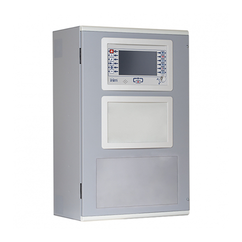
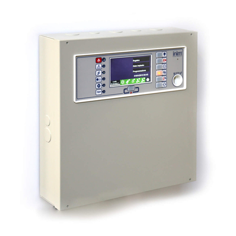
INIM Previdia Ultra User manual

User’s manual
1
CONTROL PANEL FOR FIRE DETECTION AND ALARM,
FIRE EXTINCTION AND VOICE-EVACUATION SYSTEMS
USER’S MANUAL
EN 54-2
EN 54-4
EN 54-16
EN 54-21
EN 12094-1
0051
22
0051-CPR-2741
0051-CPR-2826
0051-CPR-2827

2Warranty
Fire detection and extinguishing system
Warranty
INIM Electronics s.r.l. warrants that this product shall be free of defects in material and workmanship for a period of 24
months from the date of production. In consideration of the fact that INIM Electronics s.r.l. does not install directly the
products here indicated, and due to the possibility they may be used with other products not manufactured by INIM
Electronics, INIM Electronics cannot guarantee the performance of the security installation. Seller obligation and liability
under this warranty are expressly limited to repairing or replacing, at seller's option, any product not meeting its stated
specifications. In no case can INIM Electronics s.r.l. be held responsible or liable by the buyer or any other person for any
loss or damage, direct or indirect, consequential or incidental.
This warranty applies only to defects in parts and workmanship relating to normal use. It does not cover:
• Damage arising from improper use or negligence;
• Damage caused by fire, flood, wind or lightning;
•Vandalism;
• Fair wear and tear.
INIM Electronics s.r.l. shall, at its option, repair or replace any defective products. Improper use, that is, use for purposes
other than those mentioned herein will void this warranty. For further details regarding this warranty contact the
authorized dealer.
Limited Warranty
INIM Electronics s.r.l. shall not be liable for any damage caused by improper use of this product.
The installation and use of the products indicated herein must be carried out by authorized persons only. Moreover, the
installation procedure must be carried out in full respect of the instructions provided in this manual.
Copyright
The information contained in this document is the sole property of INIM Electronics s.r.l.
Copying, reprinting or modification of this document, in part or as a whole, is not permitted without prior authorization in
writing from INIM Electronics s.r.l. All rights reserved.

Manuale per l’utente
Table of content 3
Table of content
Warranty.......................................................................................................................... 2
Limited Warranty .......................................................................................................... 2
Copyright........................................................................................................................ 2
Table of content...........................................................................................................3
Chapter 1 General information ....................................................................................................5
1.1 Manufacturer's details .....................................................................................................................5
1.2 About this manual ............................................................................................................................5
1.3 Operator classification - Access Levels ......................................................................................5
1.4 CE Mark...............................................................................................................................................6
1.5 Operative statuses of the Previdia Ultra system.......................................................................8
1.6 Elements of the voice emergency system ................................................................................8
Chapter 2 Inim Cloud Fire .............................................................................................................9
2.1 User interface, home page ............................................................................................................9
2.2 Registration of a control panel to the Inim Cloud user account ......................................10
Chapter 3 Fire detection system user interface......................................................................11
3.1 Function buttons and indicators of the FPMCPU module.................................................. 11
3.2 Screen in standby status...............................................................................................................13
3.3 Status Bar..........................................................................................................................................13
Chapter 4 Visualization of the fire-fighting system ............................................................... 15
4.1 Viewing active events....................................................................................................................15
4.2 View events log...............................................................................................................................16
4.3 View system status......................................................................................................................... 17
4.4 Extinction module LED panel (FPMEXT) .................................................................................. 21
Chapter 5 Using the fire detection system..............................................................................22
5.1 Access to programming.............................................................................................................. 22
5.2 Device management.................................................................................................................... 22
5.3 Telephone Dialer Management (IFMDIAL) ............................................................................. 23
5.4 Management of the extinction module (IFMEXT)................................................................. 24
Chapter 6 Voice emergency system user interface..............................................................25
6.1 Function buttons and indicators of the FPAMIAS module ................................................. 25
6.2 Screen in standby status...............................................................................................................27
6.3 Status Bar..........................................................................................................................................27
Chapter 7 Visualization of the emergency voice system ....................................................28
7.1 Viewing active events................................................................................................................... 28
7.2 View events log.............................................................................................................................. 29
7.3 View system status........................................................................................................................ 29
Chapter 8 Using the emergency voice system......................................................................34
8.1 Access to programming.............................................................................................................. 34
8.2 Manual emergency activation procedure............................................................................... 34
8.3 Audio adjustment .......................................................................................................................... 35
8.4 Management of emergency telephones ................................................................................ 35
System Test..................................................................................................................37
WEEE ............................................................................................................................. 37
Appendix Quick management of fire emergencies.............................................................38
Appendix Quick management of voice emergencies ........................................................39

4Table of content
Sistema di rivelazione incendio ed estinzione

User’s manual
General information 5
Chapter 1
General information
1.1 Manufacturer's details
Manufacturer: INIM ELECTRONICS S.R.L.
Production plant: Centobuchi, via Dei Lavoratori 10
Municipality: 63076, Monteprandone (AP), Italy
Tel.: +39 0735 705007
Fax: +39 0735 704912
E-mail: [email protected]
Web: www.inim.biz
The personnel authorized by the manufacturer to repair or replace the parts of this system, hold authorization to work
only on devices marketed under the INIM Electronics brand.
1.2 About this manual
Manual code: DCMUINE0PREVIDIAU
Revision: 1.00
This manual is a guide for the end user and is intended to assist in the correct interpretation of the indications provided
by the Previdia Ultra fire detection control panel.
Part of the information available on the screen and also the correct activation of some of the visual signals on the LEDs
will be subject to the configuration carried out by the installer; who, by following the instructions for configuration,
commissioning, maintenance and programming operations in the respective manuals, ensures the proper partitioning of
the zones and the classification, addressing and configuration of the various system elements.
1.3 Operator classification - Access Levels
The control panel has 4 distinct access levels:
Level 1: Public level - this is the normal access level of the control panel and is the access level for building inhabitants
who are neither authorized to use the system nor instructed in its use.
At this level it is possible to view the information on the display and on the signalling LEDs, as well as to interact using the
buttons and the touch screen to scroll through the information. Level 1 allows the following operations only:
• mute buzzer
• test signalling LEDs
• activate alarm signalling when an early-warning process is running
Level 2: Authorized users - this access level is for the system supervisors and is for authorized personnel who are
adequately instructed in the use of the system and its functions.
Access requires the use of a key or entry of a valid access code with sufficient access rights. In addition to the operations
described for level 1 it is also possible to carry out the following operations:
• mute alarm signalling devices
• rearm the control panel
• activate alarm signalling devices manually
• disable control panel elements
• place in test status one or more of the system elements
• manual activation of emergency

6General information
Fire detection and extinguishing system
The system provides two additional sub-levels of authorized user:
-Superuser level, las for the previous one, with the added possibility of replacing a loop device and registering control
panels to their account with the Inim Cloud service
-Maintenance level, same as the previous level with the added possibility of stopping the valve pulse for those
models that support extinction functions
Level 3: Programming - this access level is for specialized technical operators who carry out system configuration,
commissioning and maintenance.
Access requires entry of a valid access code with sufficient access rights after inserting a jumper which enables
programming. Refer to the manual for system configuration, commissioning and maintenance.
Level 4: only authorized technicians, appointed by the Manufacturer can, by means of special tools, carry out repair
work on the motherboard.
1.4 CE Mark
1.4.1 Regulation (EU) No. 305/2011
These products comply with requirements stated by standards listed here below in compliance with Regulation (EU) No. 305/
2011.
0051
INIM Electronics s.r.l.
Via Dei Lavoratori 10 - Fraz. Centobuchi
63076 Monteprandone (AP) - Italy
22
0051-CPR-2741
EN 54-2:1997 + A1:2006
EN 54-4:1997 + A1:2002 + A2:2006
EN 54-16:2008
EN 54-21:2006
EN 12094-1:2003
PREVIDIA-ULTRAVOX
PREVIDIA-ULTRAVOXR
PREVIDIA-ULTRAVOXD
Control and signalling panel with power-supply equipment, alarm transmission and fault signalling
equipment, automatic electrical device for control and management of switch off and delay, control
and signalling equipment for integrated voice alarm systems for fire detection and signalling in
buildings and for gas extinguishing systems installed in buildings as part of a complete operating
system.
Essential features
Performance
Performance in the event of fire PASS
Power supply performance PASS
Response delay (response time in the event of fire) PASS
Transmission performance PASS
Operating reliability PASS
Durability of operating
reliability:
Thermal resistance PASS
Vibration resistance PASS
Humidity resistance PASS
Electrical stability PASS
Options provided in accordance with EN54-2
Performance
7.8 Output to fire alarm devices PASS
7.9 Output to fire alarm routing equipment PASS
7.10 Output to fire protection equipment PASS
7.11 Delay on outputs PASS
7.12 Co-incidence detection (Type A, B and C) PASS
7.13 Alarm counter PASS
8.3 Point fault signal PASS
8.9 Output to remote fault or warning signalling devices PASS
9.5 Addressable points out-of-service PASS
10.0 Test condition PASS
Options provided in accordance with EN12094-1
Performance
4.17 Delay of extinguishing signal PASS
4.18 Signal representing the flow of extinguishing agent PASS
4.19 Monitoring of the status of components PASS
4.20 Emergency hold device PASS
4.21 Control of flooding time PASS
4.22 Initiation of secondary flooding PASS
4.24 Triggering signals to equipment within the system PASS
4.26 Triggering of equipment outside the system PASS
4.27 Emergency abort device PASS
4.28 Control of extended discharge PASS
4.29 Release of the extinguishing media for selected flooding zones PASS
Options provided in accordance with EN 54-16
Performance
7.3 Audible warning PASS
7.5 Phased evacuation PASS
7.6.2 Manual silencing of voice alarm status PASS
7.7.2 Manual reset of voice alarm status PASS
7.8 Output to fire signalling devices PASS
7.9 Voice alarm status output PASS
8.3 Fault signalling related to the transmission path to the CCS PASS
8.4 Fault signalling related to voice alarm zones PASS
9 Out-of-service condition PASS
10 Manual command of the voice alarm system PASS
12 Emergency microphone(s) PASS
13.14 Redundant power amplifiers PASS
Additional information according to EN 54-2
About information required at point 12.2.1, see data contained in this manual.
Additional information according to EN 54-4
For the information required by point 7.1, see data contained in this manual.
Additional information according to EN 54-21
For the information required by point 7.2.1, see data contained in this manual.
Additional information according to EN 12094-1
Environmental class: A
Degree of protection: IP30
Flooding zones: up to 24
Zones from 1 a 24 for CO2, inert gas or halogenated hydrocarbons.
Response delay activation condition: max 3s
Response delay triggering of outputs: max 1s

User’s manual
General information 7
1.4.2 Directive 2014/53/EU
Hereby INIM Electronics S.r.l. declares that the above mentioned control panel models with the optional modules
comply with the essential requirements and other relevant provisions established by directive 2014/53/EU.
Following paragraph explains how to download the complete Declaration of Conformity.
This product may be used in all EU Countries.
0051
INIM Electronics s.r.l.
Via Dei Lavoratori 10 - Fraz. Centobuchi
63076 Monteprandone (AP) - Italy
22
0051-CPR-2826
EN 54-2:1997 + A1:2006
EN 54-4:1997 + A1:2002 + A2:2006
EN 54-21:2006
EN 12094-1:2003
PREVIDIA-ULTRA216
PREVIDIA-ULTRA216R
PREVIDIA-ULTRA216D
Control and signalling panel with power-supply equipment, alarm transmission and fault
signalling equipment, automatic electrical device for control and management of switch off
and delay for fire detection and signalling in buildings and for gas extinguishing systems
installed in buildings as part of a complete operating system.
Essential features
Performance
Performance in the event of fire PASS
Power supply performance PASS
Response delay (response time in the event of fire) PASS
Transmission performance PASS
Operating reliability PASS
Durability of
operating reliability:
Thermal resistance PASS
Vibration resistance PASS
Humidity resistance PASS
Electrical stability PASS
Options provided in accordance with EN54-2
Performance
7.8 Output to fire alarm devices PASS
7.9 Output to fire alarm routing equipment PASS
7.10 Output to fire protection equipment PASS
7.11 Delay on outputs PASS
7.12 Co-incidence detection (Type A, B and C) PASS
7.13 Alarm counter PASS
8.3 Point fault signal PASS
8.9 Output to remote fault or warning signalling devices PASS
9.5 Addressable points out-of-service PASS
10.0 Test condition PASS
Options provided in accordance with EN12094-1
Performance
4.17 Delay of extinguishing signal PASS
4.18 Signal representing the flow of extinguishing agent PASS
4.19 Monitoring of the status of components PASS
4.20 Emergency hold device PASS
4.21 Control of flooding time PASS
4.22 Initiation of secondary flooding PASS
4.24 Triggering signals to equipment within the system PASS
4.26 Triggering of equipment outside the system PASS
4.27 Emergency abort device PASS
4.28 Control of extended discharge PASS
4.29 Release of the extinguishing media for selected flooding zones PASS
Additional information according to EN 54-2
About information required at point 12.2.1, see data contained in this manual.
Additional information according to EN 54-4
For the information required by point 7.1, see data contained in this manual.
Additional information according to EN 54-21
For the information required by point 7.2.1, see data contained in this manual.
Additional information according to EN 12094-1
Environmental class: A
Degree of protection: IP30
Flooding zones: up to 24
Zones from 1 a 24 for CO2, inert gas or halogenated hydrocarbons.
Response delay activation condition: max 3s
Response delay triggering of outputs: max 1s
0051
INIM Electronics s.r.l.
Via Dei Lavoratori 10 - Fraz. Centobuchi
63076 Monteprandone (AP) - Italy
22
0051-CPR-2827
EN 54-4:1997 + A1:2002 + A2:2006
EN 54-16:2008
PREVIDIA-VOX
PREVIDIA-VOXR
PREVIDIA-VOXD
Control and signalling panel for voice alarm systems with integrated power-supply equipment
for fire detection and signalling systems installed in buildings
Essential features
Performance
Performance in the event of fire PASS
Power supply performance PASS
Response delay (response time in the event of fire) PASS
Transmission performance PASS
Operating reliability PASS
Durability of
operating reliability:
Thermal resistance PASS
Vibration resistance PASS
Humidity resistance PASS
Electrical stability PASS
Options provided in accordance with EN 54-16
Performance
7.3 Audible warning PASS
7.5 Phased evacuation PASS
7.6.2 Manual silencing of voice alarm status PASS
7.7.2 Manual reset of voice alarm status PASS
7.8 Output to fire signalling devices PASS
7.9 Voice alarm status output PASS
8.3 Fault signalling related to the transmission path to the CCS PASS
8.4 Fault signalling related to voice alarm zones PASS
9 Out-of-service condition PASS
10 Manual command of the voice alarm system PASS
12 Emergency microphone(s) PASS
13.14 Redundant power amplifiers PASS
Additional information according to EN 54-4
For the information required by point 7.1, see data contained in this manual.

8General information
Fire detection and extinguishing system
1.4.3 Documents for the users
Declarations of Performance, Declarations of Conformity and Certificates concerning to INIM Electronics S.r.l. products
may be downloaded free of charge from the web address www.inim.biz, getting access to Extended Access and then
selecting “Certifications” or requested to the e-mail address [email protected] or requested by ordinary mail to the address
shown in the paragraph 1.4.1.
Manuals may be downloaded free of charge from the web address www.inim.biz, getting access to Extended Access and
then selecting “Manuals”.
1.5 Operative statuses of the Previdia Ultra system
Standby: Operating status of the control panel when there is no ongoing alarm or fault signalling.
This status is altered by the occurrence of an event, that is, an operative status which is characterized by an activation
(when the event occurs) and a reset (when the event ends).
Reset: This operator-activated command annuls the current status of the control panel (and the relative signalling and
activations) and resets the system to standby.
This command can be disabled in order to prevent users from activating it by mistake and annulling active signals.
Disable: This command disables part of the system
Fault: Condition of the control panel caused by a malfunction or tamper on the operating functions of the control panel
or one of the parts of the system.
Relative to the fire extinguishing system
Alarm: Status of the control panel generated by manual activation (for instance, from a call point) or automatic
activation (signal from a detector). This is followed by an alarm signal.
Pre-alarm: This is the status of the control panel during the interval (delay) which runs between the detection of an
alarm condition and the actual signalling of the alarm (delay).
Investigate: This command is activated by a supervisor, during an early-warning condition, it provides an extension of
the early-warning delay and allows the supervisor to verify the cause of the alarm.
Fire evacuation: This command is activated by a supervisor, during an early-warning condition, it cancels the delay and
instantly activates alarm signalling (evacuation).
CPU emergency: Operating status of the control panel in the event of fault on the main CPU of the FPMCPU module
and therefore of automatic activation of the backup CPU.
The backup CPU ensures the basic functions of the system (receiving alarms from the points and activating the outputs).
However, it does not ensure all the configured activation logic. For total redundancy of all the configured functions, it is
necessary to add and configure a second FPMCPU unit to the control panel.
Relative to the voice emergency system
Voice evacuation: status of the control panel following the activation of an evacuation message by an authorized
operator or the fire prevention system, intended for the final user of the protected area.
Alert: status of the control panel following the activation of an alert message by an authorized operator or the fire
prevention system, intended for the final user of the protected area.
Staff Alert: status of the control panel following the activation of an alert message by an authorized operator or the fire
prevention system, intended for personnel working within the protected area.
Voice emergency: Operating status of the control panel following communication of voice evacuation, alert or staff
alert, for which low priority voice communications are interrupted and emergency audio sources are activated on the
programmed or selected loudspeaker lines.
1.6 Elements of the voice emergency system
Following is the description of the terminology used to define the elements of the voice emergency system:
Speakers line: they identify themselves with the modules connected to an output of the IFAMAMP amplifier module.
Generally these are loudspeakers connected in parallel on an open line or in a ring.
Audio zone: the control panel identifies itself as an audio zone, a set of loudspeaker lines that transmit the same audio
reproduction at the same time.
Audio sector: indicates a logical grouping of audio zones. Utilized if the use of zones with geographical groupings is
desired or in accordance with the system configuration needs.

User’s manual
Inim Cloud Fire 9
Chapter 2
Inim Cloud Fire
The Cloud service provided by INIM Electronics offers Previdia users a way to
manage their fire alarm control panels via the Internet, in addition to that
already possible via direct access to the control panel display.
The connection of control panels to the Cloud service is achieved via a web
interface (App or any browser) without any need to configure the network on
which the control panel is installed. In particular, it is not necessary to
program a router to perform port-forwarding and the like in order to reach the control panel.
In order to use the Cloud service, the user must have their own account at www.inimcloud.com, registered as “User”.
After login, the user will have access to a customized web interface which provides all the tools required for supervision
of all the control panels registered by the user.
In order to access Inim Cloud services as a user, registration must be carried out also by the user (paragraph 2.2).
2.1 User interface, home page
Following is the description of the home page; the presence of each of the following elements described depends on
the activated functions and the page you are accessing:
[A] Button for the selection of one of the registered control panels or clusters to which it belongs and description of the
selected control panel
[B] Buttons for access to the management sections of the selected control panel
Home
Manage System
Notifications
CLUSTER XYZ
https://inimcloud-fire.com/home
DESCRIPTIONDAYCONTROL PANEL TIMECLUSTER ELEMENT
Fire alarm01/01/2022Previdia 18:23CLUSTER XYZ Zone x
Zone y
Fire alarm01/01/2022Internal control panel 18:25CLUSTER XYZ Loop module
Interior Zone
Fire alarm01/01/2022Fire control panel 18:24CLUSTER XYZ Zone z
Loop 1
Zone w
41424
TEST
0
Ongoing
SUPERVISORY
2
Ongoing
MONITOR
2
Ongoing
EARLY WARNINGS
5
Ongoing
DISABLED
2
Ongoing
FAULTS
4
Ongoing
GAS
0
Ongoing
ALARMS
3
Ongoing
A
BE
DC
F

10 Inim Cloud Fire
Fire detection and extinguishing system
2.2 Registration of a control panel to the Inim Cloud user account
After logging in to the relevant Inim Cloud service user account, a user can request the registration of a new control
panel in addition to those the user can access via the web interface.
The control panel that a user wants to register to their account must first be registered to the Cloud service by an
installer.
1. Access the Inim Cloud service as a user.
2. By clicking on the profile management button, you access a page where you can set the
parameters of the account and the registered control panels.
In the lower section, below the list of control panels, you have the “New INIM system” section.
3. The Add button will allow you start the registration process. The Cloud service will send an OTP (One Time
Password) number consisting of 6 digits to the user. This number has a limited time duration of 15 minutes.
4. Enter your user code at the control panel you want to register
Note: In order to be able to register control panels to your Inim Cloud user account, you must have a user
code (level 2) and a “superuser” code, or higher.
5. Access the “System status” section, then “Cloud”, then under “Enroll User”
6. Enter the OTP password and wait for the outcome of the registration.
The outcome of the procedure will be shown with one of the following messages:
• “Account created!”: the control panel has been successfully registered to Cloud
• “Communicat.Error”: generic communication error.
The possible causes may be:
- no Internet connection
- date of manufacture of the control panel is earlier than dd/mm/yyyy
- date/time of control panel different, ahead of or behind the exact date/time by more than 15 minutes
• “Already enrolled”: the control panel is already registered to Cloud
• “Bad/expired OTP”: the entered password is incorrect or expired
• “Panel notEnabled”: the control panel cannot be registered to Cloud.
[C]
Buttons for quick viewing
These are always present and
overlaid show the number of
unsigned events present in the
System Register.
Alarms
This button opens a window listing the last 4 alarm or tamper events.
Faults
The button opens a window listing the last 4 fault events.
Other events
This button opens a window listing the last 4 control panel events in
addition to alarms and faults.
Cloud events
This button opens a window listing the last 4 cloud events.
[D] Buttons for user profile management
[E] Section for visualization of all ongoing signalling
[F] Text section relating to the button pressed

User’s manual
Fire detection system user interface 11
Chapter 3
Fire detection system user interface
3.1 Function buttons and indicators of the FPMCPU module
The LEDs on the sides and below the screen provide visual signals which indicate the general status of the system,
whereas the function buttons allow fast execution of all the main operations.
The key permits level 1 (public level) to pass to level 2 (supervisor level). When turned clockwise the key will generate a
pulse which places the control panel in level 2 status. The control panel will return to level 1 if no buttons are pushed
within 20 seconds.
[A] Touchscreen display
[B] Status LED
[C] LED and function
button
[D] LED and multiple-
alarm button
[E] Access-key slot
Status LED Colour On solid Flashing
Alarm Red Fire alarm running. Fire alarm memory.
Fault Yellow
A fault (of any type) is present on the
system.
The details of any active faults are
shown on the screen.
Fault memory.
A fault has been solved.
ON Green The system is functioning.
CPU Fault Yellow
The CPU of the FPMCPU module is
out of service. In this condition, the
backup CPU comes into operation to
guarantee the minimum safety
functions. Contact your service dealer.
CPU fault memory.
The CPU of the FPMCPU module
has reset and restarted.
Disabled Yellow One or more of the system
elements has been disabled.
A
B
E
D
C

12 Fire detection system user interface
Fire detection and extinguishing system
Test Yellow One or more of the system
elements has been put in test mode.
Function LEDs Colour Activation
Button
access
level function
Signalling
test Yellow The test on the visual
signalling devices is running. 1If this button is pressed and held all the LEDs
on the control panel will light.
Evacuate Red The evacuation phase has
been activated manually. 2
Button for manual activation of the signalling
devices (audible and visual) for evacuation of
the premises.
Investigate Yellow The investigation time has
been activated. 2
Button to request supplementary
investigation time and thus lengthen the
early-warning period.
Silence
buzzer Yellow The buzzer has been
silenced. 1
This button silences the control panel
buzzer.
Events which occur after silencing will
reactivate the buzzer.
Silence
sounder Yellow The sounders have been
silenced. 2
During alarm status, this button can be used
to stop the audible and visual signalling
devices.
Pressing this button again will reactivate the
silenced audible and visual signalling devices.
Reset Yellow
The reset function is
disabled. The sounders
must be silenced before the
Reset function can be re-
enabled.
2Button for the annulment of active events
and the reset of standby conditions.
Multiple
alarms Red More than one alarm is
active on the system. 2This button allows you to scroll through the
active alarm events on the screen.
Status LED Colour On solid Flashing

User’s manual
Fire detection system user interface 13
3.2 Screen in standby status
3.3 Status Bar
[A]
Buttons to access the
events logs, system status
and programming.
[B]
Status bar (always
present) shows essential
information regarding the
system.
[C]
Customizable area
(customizable during the
programming phase) for
images relating to the
status of the system
elements or customized
function buttons .
Icon Function
Selection of this area will allow you to enter a code and change the current user-
access level.
- 1 = Public level (no code entry)
- 2 = Supervision level (turn key or code entry)
- 3 = Programming level (installer code entry)
L: 1
Access level:1
Language
selection
If required by the configuration, this button will appear on the status bar.
Selection of one of the icons changes the language of the control panel.
Day/Night
status
Day Mode:
- The control panel runs the early warning phase before activating an alarm
triggered by a detector
- the sensitivity of the detectors is set in day mode
Night Mode:
- early warnings are not run
- the sensitivity of the detectors is set in night mode
- in the event of an alarm, if the sounders are silenced they will reactivate
automatically after a set time.
Mains
network
Mains power-supply functioning properly
Indicates that at least one power-supply module has detected mains failure.
Log
System Status
Programming
L: 1 01/01/2022
18:23
C
B
A

14 Fire detection system user interface
Fire detection and extinguishing system
Sounder
status
Selection of this icon accesses (at level 2) a menu which allows manual deactivation,
activation and silencing of all fire alarm signalling devices.
Fire-alarm signalling devices (sounders, etc.) are in standby status and are
operating properly.
At least one fire alarm signalling device is in fault status. Contact your service dealer.
At least one fire alarm signalling device is disabled
At least one fire alarm signalling device has been activated
Configura
tion status
No hardware anomalies on the control panel
A hardware problem has been detected inside the control panel (module
malfunction). Contact your service dealer.
Alarm
communi
cator
status
If installed, remote alarm-signalling devices (telephone dialers or communicators
to alarm receiving centres) are in standby status and operating efficiently.
A fault has occurred on a remote alarm-signalling device. Contact your service dealer.
An alarm communicator has been disabled.
A remote alarm-signalling device is operating (transmitting a communication)
An alarm communication has been sent and confirmed by the recipient
An alarm communication has been sent but not confirmed by the recipient
Fault-
communi
cator
status
If installed, remote fault-signalling devices (telephone dialers or communicators to
alarm receiving centres) are in standby status and operating efficiently.
A fault has occurred on a remote fault-communicator device.
A fault communicator has been disabled.
A remote fault-signalling device is operating (transmitting a communication)
A fault communication has been sent and confirmed by the recipient
A fault communication has been sent but not confirmed by the recipient
Indicates the current date and time, selection of this area accesses (at level 2) the
date and time setting section.
01/01/2022
18:23
Home Allows users to go directly to the home screen or, when events are active, from
the home screen to the active events screen.
Icon Function

User’s manual
Visualization of the fire-fighting system 15
Chapter 4
Visualization of the fire-fighting system
4.1 Viewing active events
When events are active, or at least a condition is momentarily active and requires notification, the standby screen on the
display (paragraph 3.2 Screen in standby status) will be replaced by a screen which provides the respective notifications.
The screen shows the active events on the system grouped in categories. These are represented by buttons at the top
([A]) which are enabled and indicate the number of events of this type active at that moment.
Touching any one of these buttons will allow you to view all the events in the respective category. These are listed in
order of occurrence. If the event has been generated by a device, tapping the respective line will allow you to access and
view the section relating to the device concerned (paragraph 5.2 Device management).
Buttons associated with the events which are not active will remain grey.
After 30 seconds of inactivity the screen will automatically go to the page containing the category of events with the
highest priority. The priority is given as follows:
1. Fire Alarm: signal associated with fire-alarm conditions. These indicate potentially dangerous conditions which
require maximum attention.
When an alarm occurs, the section directly below the event buttons ([B]) shows the early-warning countdown and,
after the alarm, a summary of the data relating to the zones involved.
2. Gas Alarm: signal associated with gas-alarm conditions. These indicate potentially dangerous conditions which
require maximum attention.
3. Early Warning: signal triggered by detectors with an early warning threshold which is set below the alarm threshold.
Cautionary alert which must be evaluated with attention and verified.
4. Supervisory: signal indicating that a device or function controlled by the system is in a condition of failure. Indicates
a risk which may jeopardize the proper operating capacity of the system. Verify the signalled condition carefully.
5. Fault: signal indicating the presence of an anomaly which might jeopardize the proper operating capacity of the
system. Contact your service dealer.
6. Monitor: signal which is not associated with alarm or fault status, configurable during the installation phase, normally
used to provide indications to the user. They are signals of minor importance and the level of attention required
depends on the use made of these signals during the system configuration phase.
[A] Buttons for event
categories
[B]
Additional information
for the last alarm
event
[C] List of active events in
the selected category
[D] Button to return to the
standby screen
Alarms
1
Faults
3Menu
First zone in alarm: Zone 01
Last zone in alarm: Zone 01
Zones in alarm: 1
1/1/2022 18:22
Previdia 1 control panel Alarm
Zone 1 Call Point 4
Loop 1 - Point 4
L: 1 01/01/2022
18:23
B
A
C
D

16 Visualization of the fire-fighting system
Fire detection and extinguishing system
7. Disablements: signal indicating the disablement of one or more of the system elements. Indicates that it is necessary
to pay attention to extent of the non-operative parts and the possible consequences.
8. Test: signal indicating that at least one of the system elements is in test status. This condition, to be applied during
maintenance operations, maintains parts of the system in non-operative status, therefore, putting the premises in
danger as the protection level of the system is reduced.
Inim Cloud: This function is available via:
Home select one of the available control panels
4.2 View events log
The “Log” button (
paragraph 3.2
- [A]
, accessible at level 1) accesses the section which contains all the saved system-events.
Each line in the list [D] represents an event which has been saved to the log.
The log shows the date and time of each event, the control panel (to the left), the event description (in the center) and
the event details (to the right). A second tap on a previously selected event (with details) accesses a page which shows all
the relative information.
It is possible to distinguish the event type by the background colour of the line:
• White, indicates events relating to normal operating status
• Red, indicates events relating to alarm status
• Yellow, indicates events relating to fault status
• Blue, indicates an event selected by tapping on the screen
Inim Cloud: This function is available via the fast viewing buttons (paragraph 2.1 - [C]) or via:
System Management > Events Log
[A]
Arrow buttons to
scroll through the
events list
[B] Button to mark the
selected event
[C] Button to exit the
open section
[D] Events list
Menu
1/1/2022 12:03
Previdia 1 control panel Code entered Code 0001
1/1/2022 13:24
Previdia 1 control panel Open output
Zone 1 Input/Output Module
Loop 1 - Point 11
1/1/2022 15:45
Previdia 1 control panel Alarm
Zone 2 Smoke detector
Loop 2 - Point 22
1/1/2022 16:33
Previdia 2 control panel Start programming
1/1/2022 16:35
Previdia 2 control panel End programming
1/1/2022 18:08
Previdia 3 control panel Power fault PSU Board
L: 1 01/01/2022
18:23
BA C
D

User’s manual
Visualization of the fire-fighting system 17
4.3 View system status
The “System Status” button (paragraph 3.2 - [A], accessible at level 1) accesses a section which allows you to view the
status of the various system elements. A superior access level (2 or 3) allows the user to work on the elements being
viewed and carry out operations such as enable, disable, activation or test.
Access to these functions is reserved to persons with supervisor level access who have been instructed in system
management and who have knowledge of the system parts.
The section dedicated to the visualization of the system status also provides the installer with the following information,
shown in the lower left corner of the section [B]:
• counter of the number of alarms starting from system installation
• firmware of the FPMCPU module (FW of the main unit and backup unit)
• minimum required revision of Previdia/STUDIO configuration software (SW)
• site specific data release (Data), progressive number of system configuration upgrades
Note: The sections here described and the relative elements are those relating solely to the fire-fighting system
and not to the homologous elements belonging to the voice emergency system.
[A]
Access buttons to
view the status of the
system elements
[B]
Serial number of the
FPMCPU module,
indicators of the
number of alarms and
system revisions
[C] Button to exit the
open section
Panel Dialler
Zones I/O Lines
Points Extinguish Board
Groups Cloud
Timer
SN:SNSNSNSN Alarm counter: ccc
FW001FPMCPU - FW:xxxxxxxxxxxxx - SW:yy.yy.yy - Date:zzz Esc
L: 1 01/01/2022
18:23
B
A
C

18 Visualization of the fire-fighting system
Fire detection and extinguishing system
The following diagram is a view of the various screens:
Panel Dialler
Zones I/O Lines
Points Extinguish Board
Groups Cloud
Timer
SN:SNSNSNSN Alarm counter: ccc
FW001FPMCPU - FW:xxxxxxxxxxxxx - SW:yy.yy.yy - Date:zzz Esc
L: 1 01/01/2022
18:23
Network Panel
N. N.
0 This panel 0This panel
1Cluster01 1 Panel
2Cluster02 2 Panel 02
3 Warehouse 3Office
4Office Panels 4 Panel 04
5 Cluster 05 5 Panel 05
6Esc 6 Warehouse
77
L: 1 01/01/2022
18:23
Zone Status
N. Description Status
1 Zone 01 Standby
2 Zone 02 Fault
3Zone 03 Standby
4 Zone 04 Standby
5 Zone 05 Alarm
6 Zone 06 Standby
Disable Test Esc
L: 2 01/01/2022
18:23
Loop Status
N. Description Status
1 Loop 01 Standby
2 Loop 02 Alarm
3Loop 03 Fault
4Loop04 Standby
5 Loop 05 Standby
6 Loop 06 Fault
Disable View Esc
L: 2 01/01/2022
18:23
Device Status
N. Description Status
1 Optical Smoke Detector Alarm
2 Heat Detector Standby
3Photo/Heat Detector Fault
4CallPoint Fault
5 Output Module Standby
6 Input Module Standby
View Esc
L: 2 01/01/2022
18:23
Loop Card: 03 Point: 03 SNSNSNSNSN
Photo/Heat Detector
Zone 02
Missing device Change Info
Turn on output Real time
Turn on LED IP Camera
Disable point Map
Disable zone Esc
L: 2 01/01/2022
18:23
Timer Status
N. Description Status
1Timer01 Not active
2Timer02 Active
3Timer 03 Active
4Timer04 Not active
5Timer06 Not active
6Timer06 Active
Disable Activate/Deacti-
vate Esc
L: 2 01/01/2022
18:23
Group Status
N. Description Status
1 Generic alarm Active
2 Generic fault Not active
3Group 03 Active
4Group04 Not active
5Group05 Active
6Group06 Active
Disable Activate/Deacti-
vate Esc
L: 2 01/01/2022
18:23
Stop alarm calls
Stop fault calls
Stop other calls
Disable alarm calls Stop all calls
Disable fault calls
Disable other calls Esc
L: 2 01/01/2022
18:23
I/O Lines
N. Description Status
1Point01 Standby
2 Point 02 Fault
3Point 03 Active
4 Point 04 Standby
5Point05 Fault
6 Point 06 Standby
Disable Activate/Deacti-
vate Esc
L: 2 01/01/2022
18:23
Extinguish Board 1 Disable Extinguishing
Disable Automatic Extinguish
Disable Manual extinguishing
Esc
L: 2 01/01/2022
18:23
Force disable Timed (minutes)
Force enable 0030
Automatic Esc
Activate
Deactivate
Automatic Esc
A
A
B
B
C
D
D
E
E
C
F
F
G
G
H
I
J
H
I
J
L
L
L
L
L
K
M
M
M
M
K

User’s manual
Visualization of the fire-fighting system 19
[A]
Buttons to access the section for the selection of the control panel whose parts you wish to view.
It is possible to select a cluster (group of control panels connected through a LAN network) and a
single control panel from the selected cluster.
After selecting the Esc button, you will be able to view the elements in the various sections
described below. If, instead, the Home button is selected or no control panel is selected the
elements shown will be those of the control panel in use.
[B]
Button to access the zones viewing section of the selected control panel.
This section is divided into pages which show a maximum of 100 zones. The arrow buttons allow
you to scroll through the pages.
The status of each zone is shown and made distinctive by colour:
- Green, zone in standby
- Yellow, zone in fault status
- Red, zone in alarm status
-Lightyellow,zonedisabled
- Blue, zone selected by tapping on the screen
By selecting a zone, it is possible for access level 2 users to place it in test status and/or change its
operating mode (refer to this table - [L]]).
[C]
Button to access the section for the selection of the loops of the selected control panel.
The status of each loop is shown and made distinctive by colour:
- Green, loop in standby
- Yellow, loop in fault status
- Red, loop in alarm status
- Light yellow, loop disabled
- Blue, loop selected by tapping on the screen
By selecting a loop and tapping on the View button it will be possible to access the loop devices
(refer to this table - [D]]). The Disable button allows you to change the operating mode (refer to
this table - [L]]).
[D]
Device status
Button to access the section for the selection of the devices on selected loop.
This section is divided into pages which show a maximum of 80 devices. The arrow buttons allow
you to scroll through the pages.
The status of each device is shown and made distinctive by colour:
- Green, device in standby
- Yellow, device in fault status
- Red, device in alarm status
- Light yellow, device disabled
- Blue, device selected by tapping on the screen
By selecting a device and tapping on the View button it will be possible to access the loop devices
(refer to this table - [E]]).
[E]
Device module
Button to access and view the section of the selected device module.
The section shown provides all the information regarding the device as well as access to the
respective functions (paragraph 5.2 Device management).
[F]
Button to access the section for the management of the output groups of the selected control
panel.
This section is divided into pages which contain a maximum of 80 groups. The arrow buttons
allow you to scroll through the pages.
The status of each group is shown and made distinctive by colour:
- Green, group activated
- Red, group disabled
- Blue, group selected by tapping on the screen
By selecting a group and tapping on the Activate/Deactivate button, it will be possible to change
its operating status (refer to this table - [M]]). The Disable button allows you to change the
operating mode (refer to this table - [L]]).
Panel
Zones
Points
View
View
Groups

20 Visualization of the fire-fighting system
Fire detection and extinguishing system
[G]
Button to access the section for the management of the timers programmed for the selected
control panel.
The activation status of each timer is shown and made distinctive by colour:
- Green, timer activated
- Red, timer disabled
- Blue, timer selected by tapping on the screen
By selecting a timer and tapping on the Activate/Deactivate button, it will be possible to change
its operating mode (refer to this table - [M]]). The Disable button allows you to change the
operating mode (refer to this table - [L]]).
[H] Button for access to the section for communicator management and access to the telephone
functions of the selected control panel (refer to the Programming manual).
[I]
Button to access the section for the visualization of the devices connected to the I/O terminals of
the selected control panel.
This section is divided into pages which contain a maximum of 80 groups. The arrow buttons
allow you to scroll through the pages.
The status of each line is shown and made distinctive by colour:
- Green, line in standby
- Yellow, line in fault status
- Red, line in alarm status
- Light yellow, line disabled
- Blue, line selected by tapping on the screen
By selecting a line and tapping on the Activate/Deactivate button, it will be possible to change its
status (refer to this table - [M]]). The Disable button allows you to change the operating mode
(refer to this table - [L]]).
[J]
Button to access the section for the management of the extinction module of the selected
control panel.
The section allows you to view the data of an extinction module and access its functions.
The arrow buttons allow you to scroll through the various modules installed on the system.
[K]
Button to access the section for the configuration of the Inim Cloud service.
A window opens containing the following buttons:
-Enroll user, for the registration procedure of the control panel to the user's account (refer to
paragraph 2.2 Registration of a control panel to the Inim Cloud user account)
-Network diagnostics, for the process that checks the various network functions required to
communicate with the Cloud and obtain useful information in the event of problems.
The information obtained is displayed in the left pane.
[L]
Button to open a window which allows you to change the enabled/disabled status of the selected element.
This window provides the following buttons:
-Disable, to disable the selected element. Other system elements which influence the
selected element (timers, inputs, detectors, etc.) cannot enable it.
Where available, it is possible to select the “Timed” option and indicate the time, in minutes,
during which the element must hold disabled status.
-Enable, to enable the selected element. Other system elements which influence the selected
element (timers, inputs, detectors, etc.) cannot disable it.
-Esc, to close the window without changing the setting.
[M]
Button to open a window where it is possible to change the activation status of the selected element.
This window provides the following buttons:
-Activate, for the activation of the selected element.
-Deactivate, for the deactivation of the selected element. Other system elements which
influence the selected element (timers, inputs, detectors, etc.) cannot activate it.
-Esc, to close the window without changing the setting.
Arrow buttons
Button to step back
Timer
Dialler
I/O Lines
Extinguish Board
Cloud
Disable
Activate/Deactivate
Esc
Other manuals for Previdia Ultra
1
Table of contents
Other INIM Control Panel manuals

INIM
INIM Prime060S User manual

INIM
INIM SmartLoop Series User manual

INIM
INIM SMARTLOOP 0051-CPR-0225 User manual

INIM
INIM PREVIDIA COMPACT User manual

INIM
INIM Previdia-Ultravox User manual

INIM
INIM SmartLine 0051 Series User manual

INIM
INIM SmartLiving 515 Installation guide

INIM
INIM GameOver SmartLiving 505 Assembly instructions

INIM
INIM SmartLight Series Assembly instructions

INIM
INIM SmartLoop2080/S Owner's manual