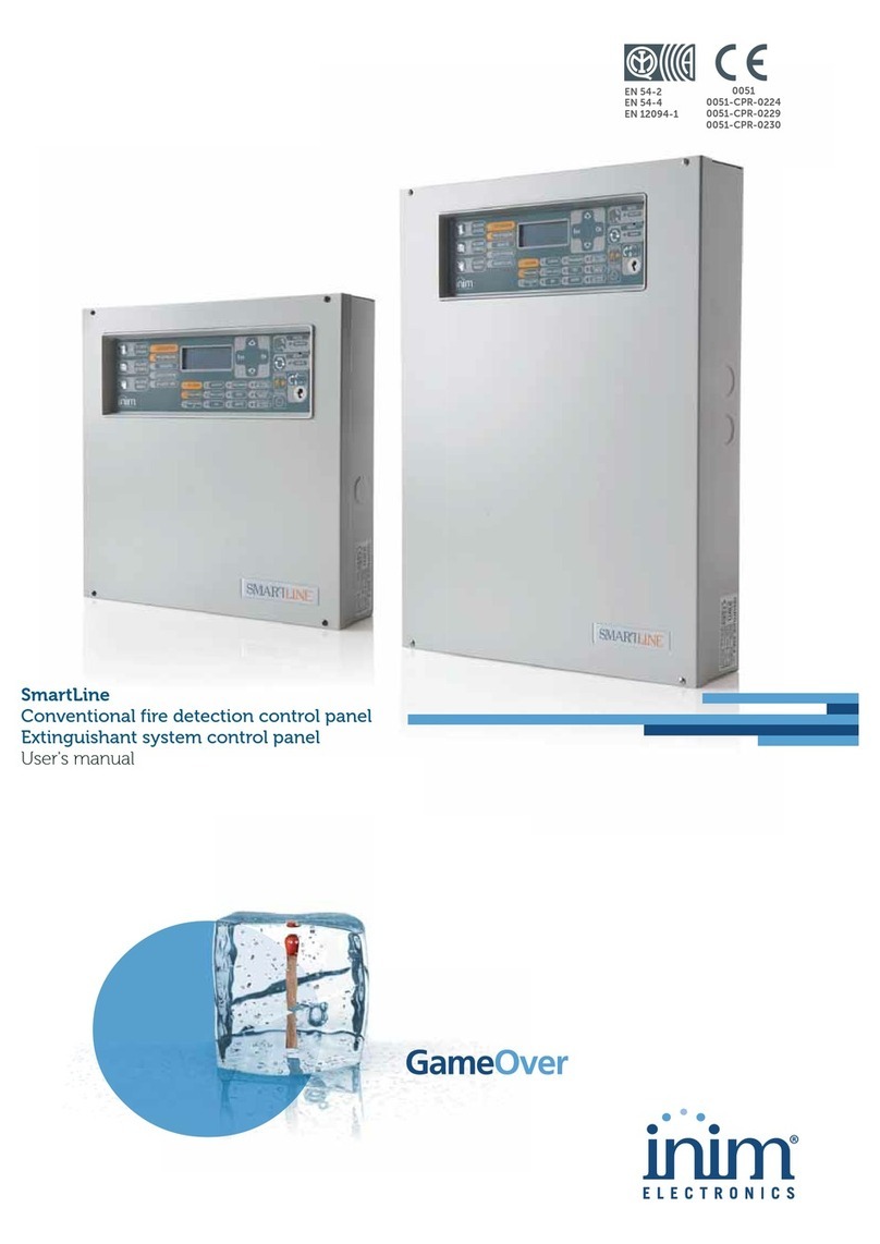
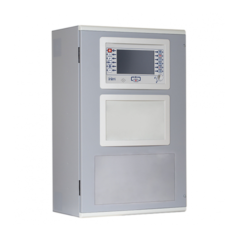
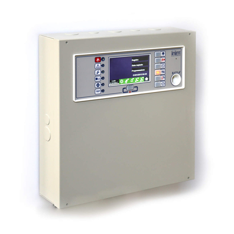
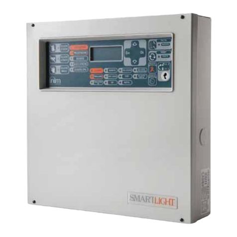
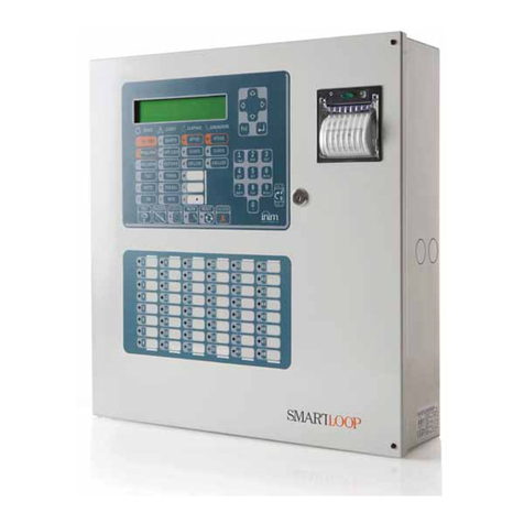
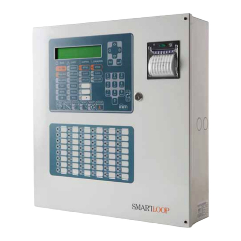
INIM SMARTLOOP 0051-CPR-0225 User manual

SmartLoop
Analogue fire alarm control panel
Programming from panel manual
EN 54-2
EN 54-4
0051
0051-CPR-0225
0051-CPR-0226
0051-CPR-0227
0051-CPR-0228
0051-CPR-0231
0051-CPR-0232

2Copyright
Analogue fire alarm control panel
Copyright
The information contained in this document is the sole property of INIM Electronics s.r.l. No part may be
copied without written authorization from INIM Electronics s.r.l.
All rights reserved.
European directive compliance
This control panel has been designed and developed to the highest standards of quality and performance
implemented by INIM Electronics s.r.l.
This control panel must be installed in accordance with the instructions described in this manual and in
compliance with the laws in force.
All control panels from the SmartLoop series are EN54-2 and EN54-4 compliant.
All control panels from the SmartLoop series, and all accessory items and special functions have IMQ-
Security systems certification, unless otherwise stated.
Declarations of performance, declarations of compliance and certificates relating to the products mentioned
in this manual can be downloaded from the following website:
www.inim.biz/certifications

Programming manual
Table of contents 3
Table of contents
Copyright ............................................................................ 2
European directive compliance ............................................... 2
Table of contents.................................................................. 3
Chapter 1 Introduction......................................................................... 5
1.1 In order to validate the IMQ-SECURITY SYSTEMS certification, and in com-
pliance with EN54-2 regulations: 5
Chapter 2 General information .............................................................. 6
2.1 Documentation supplied 6
2.2 Manual details 6
2.3 Intellectual property rights 6
2.4 Conventions 6
Chapter 3 The SmartLoop control panel ................................................. 8
3.1 The Overlay 8
3.2 The buttons 9
3.3 The LEDs 9
Chapter 4 How to use the display and keypad ....................................... 12
4.1 Selecting an option 12
4.2 Selecting a loop device 13
4.3 Editing a programming field 13
4.4 Entering numbers in a numerical programming field 13
4.5 Selecting values in a variable field 13
Chapter 5 How to view the events ....................................................... 14
5.1 Overview 14
Chapter 6 Programming the control panel............................................. 15
6.1 Panel printer 15
6.2 From computer 16
6.3 From remote computer 16
Chapter 7 The basic concepts of control panel programming ................... 17
7.1 Overview 17
7.2 The events 17
7.3 The signals 18
7.4 The zones 19
7.5 Cause/Effect actions 19
7.6 The Control panel 19
7.7 Day/Night Mode 20
Chapter 8 Configuring the system ....................................................... 21
8.1 Auto-configuration of the system 21
8.2 Restoring factory default settings 24
8.3 Viewing the configuration at panel 24
8.4 Manual configuration at panel 25
Chapter 9 Programming the system..................................................... 27
9.1 Setting the Time and Date 27
9.2 Defining the access codes 27
9.3 Setting up holiday periods 28
9.4 Setting the control panel options 28
9.5 Defining zones 29
9.6 Setting the Timers 29
9.7 How to configure loop devices 30

4Table of contents
Analogue fire alarm control panel
9.8 Programming I/O expansion boards (SmartLoop\INOUT) 31
9.9 Programming the local network (SmartLoop\NET) 32
9.10 Setting up the events printout 32
9.11 Closing the programming session 33
Chapter 10 Maintenance operations....................................................... 34
10.1 Testing/Enabling a zone 34
10.2 Testing/Enabling a detector 34
10.3 Forcing the status of the device outputs 34
10.4 Forcing the status of the control panel outputs 35
10.5 Force the device LEDs On 35
10.6 Testing the local network 35
10.7 Loop Diagnostics 36
10.8 Maintenance date 37
Chapter 11 Operating the system.......................................................... 38
11.1 Changing Day/Night mode 38
11.2 Bypassing/Unbypassing devices 38
Appendix A Record the voice messages for the telephone dialer ................ 40
Appendix B The SmartLeague software programme ................................. 41
Notes................................................................................ 43

Programming manual
Introduction 5
Chapter 1
Introduction
This Programming manual describes the essential configuration phases of a fire alarm system and the
programming process of the control panel. For a complete description of the programming process via the
SmartLeague software programme, refer to the SmartLeague instructions manual.
Regardless of the exact type of control panel, all the instructions herein are pertinent to the SmartLoop
system.
Refer to the User's Manual for the complete description of all the control-panel signaling methods (LED,
display) and the respective response actions.
Note: The control panels described in this manual have been designed and developed to the highest
standards of quality, reliability and performance adopted by INIM Electronics. All product components
are capable to application requirements and able to operate in compliance with the related technical
specifications when the temperature external to their casings complies with Category 3k5 of IEC
EN60721-3-3:1995.
1.1 In order to validate the IMQ-SECURITY SYSTEMS certification, and in
compliance with EN54-2 regulations:
1. All the manual alarm buttons and fire detectors employed in the system must be associated with fire
detection and alarm functions.
2. The functions associated with the programmable LEDs on the control panel frontplate (Keypad/Display
board and LED board), and on SmartLetUSee/LCD and SmartLetUSee/LED repeaters must be set up in
accordance with the colour of the LEDs:
•Red: alarm
•Yellow: fault, test and tamper
Note: The GAS control function is not EN54-2 compliant, due to the fact that this feature is not mentioned in
the aforesaid standard.

6General information
Programming manual
Chapter 2
General information
2.1 Documentation supplied
• Programming Manual (this document)
• Installation manual
•Usermanual
These manuals are supplied with the apparatus. For extra copies, contact the offices at INIM Electronics
quoting the order number shown in Appendix D in the installation manual.
2.2 Manual details
• Title: SmartLoop programming manual
• Version: 3.50
• Code: DCMPINE0SLOOP
• Addresses: installer, technicians
2.3 Intellectual property rights
The information contained in this document is private property. All rights reserved
No part of this document may be copied or reproduced unless expressly authorized in writing by INIM
Electronics, in particular the sections which refer to the devices specified in the installation manual.
INIM Electronics s.r.l. shall not be responsible for damage arising from improper application or use.
2.4 Conventions
2.4.1 Glossary and terminology
Device; apparatus: the device defined in the installation manual.
Left, right, behind, above, below: refer to the directions as seen by the operator in front of the mounted
device.
Pulse Output: same as “monostable output”.
Communicator (telephone, SMS, digital):same as “dialer”.
Qualified personnel: those persons whose training, expertise and knowledge of the laws and bylaws
regarding service conditions and the prevention of accidents, are able to identify and avoid all possible
situations of danger.
Select: click on and select a specific item (from drop-down menu, options box, graphic object, etc.).
Press: click on a video button.

Programming manual
General information 7
2.4.2 Graphic conventions
Following are the graphic conventions used in the text. For the description of the text rules refer to Chapter
3 - The SmartLoop control panel and Chapter 4 - How to use the display and keypad.
Note: The detached notes contain important information about the text.
Attention: The attention prompts indicate that total or partial disregard of the procedure could damage
the connected devices.
Danger: The danger warnings indicate that total or partial disregard of the procedure could injure the
operator or persons in the vicinity.
Conventions Example Description
Text in Italics Refer to paragraph
2.4.2 - Graphic
conventions
Text in italics: indicates the title of a chapter, section, paragraph,
table or figure in this manual or other published reference.
<text> <CustomerCode> Editable field
[lowercase letter]
or [number]
[A] or [1] Representation of a part of the system or video object.
BUTTON Esc, RESET Computer or control panel keys.

8The SmartLoop control panel
Programming manual
Chapter 3
The SmartLoop control panel
3.1 The Overlay
All the models in the SmartLoop series, except for SmartLoop2080/S and SmartLoop1010/S (flush front
with no display or keypad), have the following overlay:
[A] 40 character x 4 line alphanumeric display. Indicates the system status, signals critical events (with priority
given to the most serious events) and allows you to navigate through of the main menu and screens.
[B] Keys S, T, W, and Xallow you to move and work on the menu screens.
[C]
The
Esc
key allows you to quit an operation and exit the screen without saving, or go to the options of a higher-
level menu.
The
key allows you to confirm an operation and exit a screen, or go to the options of a lower-level menu.
[D] Alphanumeric keypad for data entries.
Key 1allows you to view the specifics of events which provide detailed information.
If an event relating to a loop device is shown on the display, key 2will allow you to access the bypass/
unbypass loop device menu (refer to paragrafo 11.2.1) .
[E] Pre-configured status LEDs.
[F] Programmable status LEDs (yellow).
Customizable.
This LED will blink during the programming phase.
[G] Fast buttons for use in the event of alarm or fault.
[H] Keyswitch: allows level 2 users (Users, Authorized Users) to access the system. Can be used instead of code
entry.
C
D
E
F
G
AB
H

Programming manual
The SmartLoop control panel 9
3.2 The buttons
3.3 The LEDs
TEST Initializes the test phase and acyivates all the control panel LEDs.
BUZZER Silences the control panel buzzer. The buzzer will be enabled automatically if
another event occurs. RESET operations also silence the buzzer.
INVESTIGATE During Pre-alarm status, this button will activate a pre-set alarm delay.
SILENCE If this button is pressed once, it will silence the NAC outputs, fault output
and all the 'Silenceable' outputs. If this button is pressed again (when the
LED is On), it will toggle (undo) the silence command.
RESET Resets the control panel (clears alarms).
EVACUATE Activates the evacuation procedure. If this button is pressed by a member of
the public (Level 1- no access code or key required) during pre-alarm status,
it will generate an instant alarm.
If this button is pressed by a “User” or “Authorized User” (Level 2), it will
generate an instant alarm regardless of the system status.
STATUS group
Description Colour If On solid:
ALARM Red The control panel is in alarm status. This LED goes On to signal
the following conditions:
- alarm status of a point defined as an “Alarm” point
- the evacuation phase is running (triggered by the EVACUATE
button on the control panel or on a connected repeater panel)
- the evacuation phase is running (triggered by the EVACUATE
button a Network control panel or on a Network repeater panel)
PRE-ALARM Red The control panel is in pre-alarm status. This LED goes On to
signal the alarm status of a point programmed as an “Alarm”
point with the “Pre-alarm” attribute.
DISABLED Yellow If this LED is On, at least one of the system objects (point, zone,
output, communicator, etc.) has been disabled.
TEST Yellow If this LED is On, at least one of the system objects (point, zone,
output, communicator, etc.) is in test status.
A zone test affects all the points of the zone concerned.
NIGHT MODE Yellow If this LED is On, the control panel is operating in night mode.
During Day mode, the control panel can generate pre-alarms and
hold silence status for an unlimited time. During Night mode, the
control panel can hold silence status for the pre-set time only.
During Night mode, the control panel cannot generate pre-alarms
as this function is disabled.
ON Green If this LED is On, the control panel is fully powered and operative.

10 The SmartLoop control panel
Programming manual
FAULTS group
Description Colour If On solid: If blinking:
FAULT Yellow If this LED is On (solid), at least
one system fault has been
detected. The other LEDs in this
group indicate specific fault
conditions.
If this LED blinks, a fault has
been cleared and saved to the
memory.
You can access the events log
and view the event/s concerned.
CPU FAULT Yellow If this LED is On (solid), the logic
unit is not working properly
(motherboard microprocessor).
Under such circumstances,
immediate technical assistance
is required as system
functionality is gravely at risk.
The cause of this fault must be
cleared and the motherboard
microprocessor must be restored
to proper working order.
If this LED blinks, the
motherboard microprocessor has
reset (due to system shutdown
or jamming).
Danger: Under such
circumstances,
the efficiency
of the entire
system must
be checked.
This LED will
stop signaling
(LED Off) when
the panel
resets.
BATTERY Yellow If this LED is On (solid), the
battery is not working properly.
This may be due to either
battery inefficiency, in which
case the batteries must be
changed; or to a drop in power-
supply voltage (below the level
of the programmed threshold),
in which case the voltage must
be restored in such way as to
allow the power supply to charge
the batteries properly.
If this LED blinks, a battery fault
event has been cleared and
saved to the memory.
EARTH Yellow If this LED is On (solid), voltage
dispersion to earth has been
detected. Immediate
maintenance is required to clear
this fault.
If this LED blinks, a voltage-
dispersion-to-earth event has
been cleared and saved to the
memory.
FUSE Yellow If this LED is On (solid), one of
the resettable fuses has been
interrupted. This fault may be
due to a malfunction related to
the AUX and AUX-R terminal
connections.
If this LED blinks, a malfunction
related to the AUX and AUX-R
terminal connections has been
cleared and saved to the
memory.
MAINS Yellow If this LED is On (solid), the
Mains power is not present
(blackout), therefore, the control
panel power supply is unable to
power the system and charge
the batteries.
If this LED blinks, a Mains failure
event has been cleared and
saved to the memory.
Programming manual
The SmartLoop control panel 11
BELLS group
Description Colour If On solid: If blinking:
ACTIVE Red If this LED is On (solid), at least
one of the 4 NAC outputs on the
control panel motherboard or
on the SmartLoop/INOUT
expansion board (programmed
to activate in the event alarm)
or NAC alarm output is active.
FAULT Yellow If this LED is On (solid), at least
one of the 4 NAC outputs on the
control panel motherboard or
on the SmartLoop/INOUT
expansion board (programmed
to activate in the event alarm)
or NAC alarm output is active.
If this LED blinks, one of thee
above-mentioned events has
been cleared and saved to the
memory.
DISABLED Yellow If this LED is On (solid), at least
one of the 4 NAC outputs on the
control panel motherboard or
on the SmartLoop/INOUT
expansion board (programmed
to activate in the event alarm)
or NAC alarm output has been
disabled.
DIALLER group
Description Colour If On solid: If blinking:
ACTIVE Red If this LED is On (solid), the
system is sending a
communication generated by
the SmartLoop/PSTN and/or
Smart/LAN telecom board
related to an alarm or fault
event.
If this LED blinks, the system is
sending a communication
generated by the SmartLoop/
PSTN and/or Smart/LAN
telecom board that is not related
to an alarm or fault event.
FAULT Yellow If this LED is On (solid),
communication with the
SmartLoop/PSTN board is not
possible or a fault has been
detected on one of the two
telephone lines (L.E. or L.B.).
If this LED blinks, a fault
relating to the SmartLoop/PSTN
board or telephone lines has
been cleared and saved to the
memory.
DISABLED Yellow If this LED is On (solid), alarm
related telephone
communications generated by
the SmartLAN board and/or
fault related telephone calls
generated by the SmartLAN
board cannot be sent.

12 How to use the display and keypad
Programming manual
Chapter 4
How to use the display and keypad
All SmartLoop models, except for the SmartLoop2080/S and SmartLoop1010/S, allow users to operate the
system from the control panel keypad. All control panels allow users to operate the system from their
connected SmartLetUSee/LCD Repeater panels.
This section describes how to navigate and work on the menu screens.
Attention: The procedures described in this section will not be repeated in other parts of this manual,
however, any exceptions to this procedure will be described.
4.1 Selecting an option
This section describes how to navigate through the menus and which options to select:
From panel:<key>, Programming, <code>, Configuration, Modify Configuration, AUTO Enroll, Loop,
or: <key>, 8, <code>, 1, 2, 1, 2
4.1.1 Scrolling the menu
Press any key to access the Main menu.
Use keys Sand Tto scroll the list.
Press
to access the menu option (open another menu or
screen).
An ‘
L
’ indicates that the menu options continue after the last line.
Press Esc to step back to the previous level.
4.1.2 Entering the number of the menu options
If you already know the numbers of the menu options, press the
respective number/s on the keypad. For example:
1. Settings
2. Enter the Access Code
3. Configuration
4. View configuration
5. RS485 BUS
Type in:
8, <code>, 1, 1, 3
SmartLoop In Service
No Alarm
No Fault
01/01/00 00:45 Sat
J
1 Read Log
2 Check detector status
3 Panel settings
4 Disable
L
5 Dialler Settings
K
6 Printer Settings
7 Maintenance
J
8 Programming
L

Programming manual
How to use the display and keypad 13
4.2 Selecting a loop device
To select a function that operates at loop device level (e.g. Testing), you must first select the respective
loop then the point the device is assigned to. For example:
Select the loop.
Press
to view the connected devices.
Select the device.
Press
to view the device screen related to
the requested function.
This can also be done by typing in the
requested number:
<key>, 8, <code>, 2, x, yyy
‘x’ represents the loop number and ‘yyy’ the
device number.
4.3 Editing a programming field
Press keys Wand Xto move along the string.
Press the key which comprises the required
letter (in the same way as you would use a
mobile phone).
Press
to confirm the entry or press Esc to
exit and step back to the previous screen, the
entered data will be saved.
4.4 Entering numbers in a numerical programming field
Use keys Sand Tto move from one editable
field to another.
Use keys Wand Xto increase/decrease the
selected value or, alternatively, enter the
value from the keypad.
Press Esc to exit and step back to the
previous screen, the entered value will be
accepted.
4.5 Selecting values in a variable field
Use keys Sand Tto scroll the list and move
from one editable field to another.
Use keys Wand Xto toggle the value in the
field (e.g. YES, NO).
Press Esc to exit and step back to the
previous screen, the selected value will be
saved automatically.
J
1 Loop 1 < Loop Type >
2 Loop 2 < Loop Type >
3 Loop 3 < Loop Type >
4 Loop 4 < Loop Type >
L
J
001 <Detector type> < Description >
002 <Detector type> < Description >
003 <Detector type> < Description >
004 <Detector type> < Description >
J
Zone 001 _corridor floor 1
Release zonal door holder
in case of: Fire Alarm
Double-knock window
Inside
the zone : ---
J
Pre-alarm Time : _30
Investigation Time : 060
Pre-alarm: YES
Early Warning NO
J
Fault _ES
Monitoring NO

14 How to view the events
Programming manual
Chapter 5
How to view the events
5.1 Overview
The system displays and deals with real-time events in the following order of priority: Alarm, Pre-alarm,
Early Warning, Supervision, Fault, Monitor, Disable, Test (refer to paragraph 7.2 - The events). All events
are shown on the control and repeater panel displays. Events may be generated by any of the control
panels in the network (refer to Chapter 9 - Programming the local network (SmartLoop\NET)) and can be
printed via the on-panel thermal printer (SmartLoop2080/P and SmartLoop1010/P models only) or via a
serial printer (refer to Chapter 9 - Setting up the events printout).
If several events of the same type occur successively (e.g. three fault events), only the first event will be
shown on the display. If several events of different types occur successively (e.g. three faults and a pre-
alarm event), the first critical event will be show on the display (in this case,) the prealarm event).
Control panel RESET operations clear all the events from the display, however, all events will be saved to
the log and can be viewed on the control panel and via the software application.
5.1.1 Active Events
These are the events that occurred after the last control panel RESET operation.
This is the first of three events. Use keys S
and Tto view other active events.
Press Esc to view the Events menu:
Press
to select the menu option.
The option from menu 3 shows all the events
related to the current event type.
From panel: <key>, Read Log,
or: <key>, 1
FAULT 001 of 003
SMART-Loop
Telephone Line 01/01/2011 14:34 PM Fri
J
1 Main menu
2 View Log
3 View Faults

Programming manual
Programming the control panel 15
Chapter 6
Programming the control panel
The SmartLoop control panels accept different configuration and programming methods which can be
combined to suit particular installation requirements.
6.1 Panel printer
If you are working on a particularly difficult installation with console-equipped control panels (i.e. control
panels with keypads and displays), you can install the system (control panel, attachment boards, loop
devices, etc.), then instruct the control panel to assign addresses to the loop devices automatically. Once
this phase has been completed, you can upload the data to your computer and use it for the successive
programming phase, or proceed with programming from the control panel.
The configuration/programming operations via control panel are reserved for the installer company
technicians (level 3), who can:
1. By means of a screwdriver or similar tool, remove the screws and open the panel enclosure.
2. Place the programming jumper in the correct position (refer to
paragraph 4.2 - [N] in the installation
manual). The control panel comes with the jumper already inserted (factory setting).
3. Access the Programming menu.
4. Type in a code which allows access to the programming phase.
Note: The access PIN is “00004” at default.
Operators with authorization to use this code can access all programming and maintenance functions.
Attention: Some programming functions cannot be accessed through the control panel.
6.1.1 Accessing the main menu
Once you have placed the jumper in the
correct position, select the Programming
option from the main menu.
Type in a code which allows access to the
programming phase (level 3 access).
If the jumper is not connected properly, the
display will show the respective message.
Note: Access to the programming phase from a computer will not be allowed unless this jumper is connected
to the control panel.
5 Dialler settings
6 Printer Settings
7 Maintenance
J
8 Programming
L
Enter Code
-----
Internal Programming jumper
NOT inserted !!!

16 Programming the control panel
Programming manual
6.2 From computer
If you prefer to plan the layout of the system beforehand, or if you are working with control panels which
are not equipped with keypads and display, you can prepare the system layout and/or set parameters
without leaving your office. The data can be downloaded to the system later.
For further details refer to the SmartLeague programming software.
6.2.1 Enabling programming via PC
All functions can be accessed without connecting to the control panel; connection is necessary only for
upload and download operations.
1. By means of a screwdriver or similar tool, remove the screws and open the panel enclosure.
2. Place the programming jumper in the correct position (refer to
paragraph 4.2 - [N] in the installation
manual). The control panel comes with the jumper already inserted (factory setting).
3. Connect the computer to the RS232 or USB port. The connection cable must be long enough to reach
the mounted device without difficulty (refer to the installation manual, paragraph 7.12 - Connecting to
a PC).
4. Start the SmartLeague software application.
5. Type in a code which allows access to the programming phase. On startup, the Installer or Maintenance
access code (level 3) is already set.
Note: It is advisable to program the entire system via computer and use the control panel for minor changes
only.
6.3 From remote computer
If you are working on a console-equipped control panel (i.e. control panel with keypad and display) from a
remote location (for monitoring or software maintenance purposes), you can set up the control panel for
programming, connect to the Internet and, using a password-protected virtual control panel, carry out the
desired operations.
6.3.1 Initializing remote programming
The programming and maintenance operations are the same as when using the SmartLeague software
application. However, it is necessary that:
• the programming jumper is placed in the correct position (refer to
paragraph 4.2 - [N] in the installation
manual).
• the SmartLAN or SmartLAN/SF board is configured to allow Internet access.
Accessing remote programming:
1. Connect to the Internet.
2. Open the Internet browser and enter the IP address of the control panel.
3. Enter the Access Code
Refer to Chapter 9 - Programming the local network (SmartLoop\NET).

Programming manual
The basic concepts of control panel programming 17
Chapter 7
The basic concepts of control panel programming
7.1 Overview
The the SmartLoop control can:
• Trigger “events” which indicate its own status and that of its peripheral fire-detection devices. The events
are signaled on the LEDs and display and then saved to the events log.
• Control, by means of the loop-device outputs and NAC outputs, its peripheral devices (e.g. bells,
pressure valves, remote LEDs, etc.).
The first task - “monitoring” - involves dealing with fault conditions and the status changes of the system
devices. Analogue devices activate when their values exceed their Early warning and/or Alarm thresholds;
whereas, digital devices activate when they switch On/Off.
Each activation can be “controlled” by means of the programming options which generate the various event
types: Alarm, Pre-alarm, Monitor, Supervisory, Early Warning or Generic activation. Faults, however, always
generate fault events (unless you choose to program the system to ignore specific fault conditions). All
events are saved to the events log (which can be viewed via computer or control panel) and are signaled
on the control panel display and LEDs (refer to paragraph 7.2 - The events).
Each event influences the 16 device statuses (e.g. Alarm, Pre-alarm, Evacuation, etc., refer to paragraph
7.3 - The signals) and modifies the respective values. The second task “control” is based on the 16 statuses
and is managed by the zones (which represent different groups of strategically positioned devices). In this
way, each zone is independent and operates autonomously on each separate output. In order to allow this,
it is necessary to configure each input device accurately.
• For each input device configure:
- which of the 16 signals it will activate
- the “cause/effect” actions it will activate (maximum three)
- the direct actions on the control panel and on specific zones
•Foreachzone:
- the delays which will determine the zone Alarm and Evacuate signals
- the “cause/effect” actions it will activate (maximum three)
In this way, the zone determines which type of control algorithm to apply.
• For each NAC output on the control panel and for each device on the loop:
- which signals activate the output, whether received from the control panel, zones, other devices or
from the device itself and or the “cause/effect” actions (maximum three)
7.2 The events
Each event provides the following details:
• name of the device
• zone it belongs to
• date and time of its occurrence
These details are saved to the log and can be viewed via computer or control panel, and are also indicated
on the display and/or LEDs (refer to Chapter 5 - How to view the events).
A device will generate a “fault” event if a fault condition occurs, and an Early Warning event when its
analogue value exceeds its Early Warning threshold.
If its value exceeds its alarm threshold (this is a programmed value for analogue devices and an On/Off
switching signal for digital devices), it will generate an Alarm, Pre-alarm, Monitor, Supervisory or Generic
activation event in accordance with its “Activation type” (as defined during the device programming
phase).

18 The basic concepts of control panel programming
Programming manual
Depending on the programmed activation type of a device, it is possible to activate or ignore specific zone
signals.
• A device with “Alarm” activation type can activate the following signals: Pre-alarm, Arm, Evacuate,
Extinction, Fire door holders, Sprinkler On, Voice Alarm.
• A device with “Monitoring” activation type can activate Monitor signals.
• A device with “Supervisory” activation type can activate Supervisory signals.
• A device with “Silent” activation type can activate the following signals: Stop extinction, Fire door
holders, Change class, Voice Alarm.
Devices can also activate Fault and Early Warning signals.
7.3 The signals
Each device can be programmed to various zone and control panel signals in accordance with its own status
(e.g. fault, pre-alarm, etc.). In turn, these signals can be used to activate the respective outputs of each
zone.
The signals which can be activated depend on the activation type of the device concerned.
Following are the signals relating to the control panel and various zones which can be activated by the
devices. These signals are restricted by the zone parameters (e.g. Activate fire doors in the event of pre-
alarm, etc.), by “cause/effect” actions activate or inhibit these signals and by zone interaction.
Alarm Signal used for alarm signaling. Activated by alarm points belonging to the zone.
Double knock Zone signal which occurs when at least two devices belonging to the zone
concerned go into alarm status.
Evacuate Signal for second-alarm-level management (an alarm confirmed by a manual
operation or after the expiry of a delay).
Extinction Signal to be used for the activation of the fire-extinguishing system.
Stop extinction Activation of this signal will interrupt the countdown of the delay which precedes
activation of the fire-extinction system of the zone concerned. Any device which
activates this signal will block the respective zone extinction signal (whether
already active or about to activate).
Fire door holder This signal can be used to command the outputs which control the fire doors
holders. It will be generated either in accordance with the zone settings (Activate
fire door holders in the event of ...) or after a direct activation command (from
devices, etc.).
Pre-alarm This signal activates during the pre-alarm time of one or more of the zone
detectors. It can be used to activate specific warning signals to alert Security
personnel.
Sprinkler On This signal activates when at least one of the zone devices, capable of generating
the “Sprinkler On” signal, activates (e.g. Flow detector in sprinkler-system
pipes). This signal allows the system to handle separately an alarm triggered by
the activation of a sprinkler.
Early Warning This signal activates when at least one of the zone devices, capable of generating
the “Early Warning ” signal, exceeds the early warning threshold. This signal
allows the system to activate signaling in response to an anomalous rise in the
values of some detectors.
Fault This signal activates when one or more devices belonging to the zone signals
fault status.
Supervisory This signal (activated by devices belonging to zones with this attribute) allows
the system to manage fault signals related to a components of the fire-
prevention system but extraneous to the SmartLoop system (e.g. This signal can
be used to control the sprinkler pipe valve, etc.).
Monitoring This signal (activated by devices belonging to zones with this attribute) allows
the system to manage functions which are not related the fire-detection system
such as building automation functions (e.g. “Cold room door open” output signal,
etc.).

Programming manual
The basic concepts of control panel programming 19
7.4 The zones
The zones represent the “physical” components of each control panel and are associated with loop devices
(e.g. Basement zones receive signals from the devices installed in the basement). The 16 signals managed
by each zone change status in accordance with the corresponding signals generated by their associated
devices, taking into account the settings implemented by the installer during the system configuration.
The 16 signals managed by each zone can also be influenced by a “cause/effect” action which blocks or
forces some of them to activate when it triggers.
For example, a zone can go into Early Warning status if:
• at least one device has exceeded the programmed Early Warning threshold and the Early Warning signal
to the zone it belongs to is enabled;
• the “cause/effect” equation which activates the Early Warning signal of the zone is “TRUE”.
Furthermore, the zone has internal “times” (e.g. Pre-alarm time, Investigation time, etc.) which influence
the Pre-alarm, Alarm, Investigation, Evacuation, Fire door holders, Extinction and Voice alarm signals.
For example, if a zone receives an Alarm signal from at least one of its devices, it will wait for the Pre-alarm
time to expire before activating an alarm. Or, if a zone receives an Evacuate signal, it can activate the
Emergency light group which in turn will activate the outputs that drive the Emergency lights. Or, it can
activate a “cause/effect” action that blocks the fire-door holder signal to the zones thus avoiding the
activation of the associated outputs.
The signals that activate on a zone can activate the loop device outputs of the NAC outputs. The latter, as
well as being supervised outputs, are able to manage different combinations of On/Off status (for instance,
they can manage the different intermittent sounds emitted by sounders and similar devices).
In order to influence the statuses of the zones which belong to different control panels in the same
network, it is necessary to use coincident zones (programmable exclusively via the respective software
application).
7.5 Cause/Effect actions
A “cause/effect” action (programmable exclusively via the Smartleague software programme) instructs the
control to carry out a response action (“effect”) when the correlated trigger action (“cause”) occurs.
The software application provides a list of events, which allow you to select the “cause” and a list of
actions, which allows you to select the correlated “effect” (point activation, bypass zone, etc.).
For details, refer to the respective section in the software programme manual.
7.6 The Control panel
The control panel to all effects is a zone which manages 16 signals and the following operating modes:
Investigation, Reset, Silence, Day/Night.
Besides being influenced by manual operations (for example, an INVESTIGATE command from the control
panel), the control panel status and signals can be influenced by the activation of signals generated by
input devices, or by the activation of a “cause/effect” action (refer to the SmartLeague software
programme).
The control panel signals can be used to command the outputs (for example, to monitor a reception area).
Change Class This signal can be used to activate the outputs separately from the alarm.
Voice Alarm This signal allows the system to manage a voice alarm device. This signal is
activated by the zone settings (“Activate voice alarm signal in the event of...”) or
by direct activation (devices, etc.).
Bypassed Zone This signal indicates the “bypassed” or “Off” status of a zone. The zones can be
bypassed in different ways (by “cause/effect” actions, operations at the control
panel, etc.).
Test Zone This signal indicates the “Test” status of a zone. The zones can be put into test
status in different ways (by “cause/effect” actions, operations at the control
panel, etc.).

20 The basic concepts of control panel programming
Programming manual
7.7 Day/Night Mode
The control panel has two operating modes: Day and Night. The behaviour of the control panel depends on
the set operating mode
7.7.1 Day
There are people in the building, therefore, those in charge of the safety of the building and its occupants
should be duly informed before the evacuation command is given.
Silence: silences (turns Off) the panel buzzer and silenceable outputs. The silence command will be
undone automatically, if a new alarm event occurs (e.g. another detector signals alarm
conditions).
Pre-alarm: some points can be programmed to signal pre-alarm status. If no-one intervenes during the
pre-alarm phase, the system will generate an alarm when the programmed pre-alarm time
expires. Refer to paragraph 9.7 - How to configure loop devices to enable/disable the pre-alarm
time of points.
Alarm: detectors can be programmed with a Day mode alarm threshold and Night mode alarm
threshold, refer to paragraph 9.7 - How to configure loop devices.
7.7.2 Night
There are no people in the building, therefore, there is only one person in charge of building safety (e.g.:
night watchman, guard).
Silence: the silence command will act as a signaling delay. The silence phase will run for the pre-set
time. If no-one intervenes during this phase, the system will undo the silence command and
the alarm will continue.
Pre-alarm: the pre-alarm signal can be disabled on specific points. Alarm events will generate instant
alarms. Refer to paragraph 9.7 - How to configure loop devices to enable/disable the pre-alarm
time on points during Night mode.
Alarm: detectors can be programmed with a Day mode alarm threshold and Night mode alarm
threshold, refer to paragraph 9.7 - How to configure loop devices.
This manual suits for next models
5
Table of contents
Other INIM Control Panel manuals

INIM
INIM SmartLine 0051 Series User manual

INIM
INIM SmartLoop2080/S Owner's manual

INIM
INIM SmartLoop Series User manual

INIM
INIM SmartLiving 515 Installation guide

INIM
INIM Previdia-Ultravox User manual

INIM
INIM Previdia Ultra User manual

INIM
INIM Prime060S User manual

INIM
INIM SmartLight Series Assembly instructions

INIM
INIM PREVIDIA COMPACT User manual

INIM
INIM GameOver SmartLiving 505 Assembly instructions