Innovative Neutronics WalkAide User manual

LM06 -2 10/10
© 2010 Innovative Neurotronics. All rights reserved. All trademarks and registered trademarks
are the property of their respective holders. No part of this manual may be reproduced in any form
without the written consent of Innovative Neurotronics Incorporated. Information in this manual is
for the use of qualified clinicians only.
The WalkAide®System
Clinician Manual
INDEPENDENCE
one step at a time
Caution: USA Federal Law restricts this device to sale by or on the order of a physician.
2 1
Table of Contents
1.0 Introduction 2
1.1 Indications of Use 4
1.2 Contraindictions 4
1.3 Warnings About FES 4
1.4 WalkAide Specific Warnings 5
1.5 Precautions 6
1.6 Regulatory Information 7
1.7 Adverse Reactions 7
1.8 Cautions 7
1.9 Glossary 8
2.0 Equipment 13
2.1 Clinician Kit 13
2.2 Patient Kit 13
2.3 Demo Kit 14
2.4 WalkAide Bi-Flex Cuff 14
2.5 WalkAide Cuff Disposable Liner 16
2.6 Symbols and Definitions 18
3.0 Installation of the WalkAnalyst Program 20
4.0 Set-Up Procedures for WalkLink 21
5.0 Overview of Data Collection and Programming Process 27
5.1 Testing with the Peripheral Nerve Stimulator 28
5.2 Electrode Placements and Final Preparations for Walking 31
5.3 WalkAnalyst Login 35
5.4 Rapid Programming 36
5.5 Rapid Adjustment 38
5.6 Standard Programming 39
5.7 Exercise Mode 46
5.8 Wearing Schedule 47
5.9 Usage Log 49
6.0 Use and Care of the WalkAide and Accessories 53
6.1 Care and Use of WalkAide Electrodes 54
6.2 Additional Information 55
7.0 Troubleshooting 56
7.1 WalkAide Control Unit Troubleshooting 56
7.2 The ABC’s of Electrode Placement 58
7.3 Manual Adjustment of the Stimulation Parameters 59
7.4 Anatomy of Tilt and Heel Data 70
7.5 Follow-Up and Re-Optimization 71
7.6 WalkLink and Bluetooth Troubleshooting 74
8.0 WalkAide User Manual 77
9.0 Technical Information 78
10.0 Contact Information 79
EC REP
Medical Device & QA Services
76 Stockport Road
Timperley, Cheshire
WA15 7SN
United Kingdom
Tel: 0161 980 4310
Email: [email protected]
0086

2 3
1.0 Introduction
The WalkAide is a battery-operated, single-channel electrical stimulator that can be used for
functional electrical stimulation (FES). It utilizes a Tilt Sensor and accelerometer to control
the timing and duration of the stimulation during walking. A Hand Switch on the WalkLink
is used by the clinician during set-up to manually trigger stimulation while the Heel Sensor
collects additional load bearing data (Figure 2-3). The clinician uses the WalkAnalyst software
on a laptop computer to program the Tilt Sensor in the WalkAide. Use of the Tilt Sensor to
trigger stimulation eliminates the need for additional components and external wires from a
Heel Sensor during regular use.
The WalkAide produces controlled dorsiflexion of the foot during the swing phase of
gait. This small medical device attaches to a molded cuff located just below the knee. Two
electrodes are specifically placed near the head of the fibula, directly over the motor nerve
and proximal musculature. During the gait cycle, the WalkAide stimulates the common
peroneal nerve which innervates the tibialis anterior and other muscles that produce
dorsiflexion of the ankle. Users of the WalkAide are people who have lost the ability to
voluntarily lift their foot during walking, often as a result of damage to the central nervous
system from conditions such as stroke, incomplete spinal cord injury, traumatic brain injury,
cerebral palsy and multiple sclerosis. This type of stimulation will not work for people who
have damage to the lower motor neurons/peripheral nerves.
Figure 2: Initial WalkAide set-up procedure using the WalkLink,
Heel Sensor and WalkAnalyst software.
1. Clinician Heel Sensor is
placed in the user’s shoe. 3. Clinician addresses foot drop by
pressing the manual STIM button on
the WalkLink.
2. User walks straight line
and/or figure-8 with WalkAide in place
and connected to WalkLink.
4. Notebook, desktop or
tablet PC collects Heel, Tilt
and Hand Switch data for
clinician.
Figure 1: The WalkAide is a functional electrical stimulator
designed for people with foot drop

4 5
Medical Supervision—FES should only be used under the medical supervision of a physician and a
qualified clinician.
Two-Way Radios—Care should be taken while using FES therapy in close proximity (e.g. less than 1
meter) to devices which emit radio frequencies such as cellular phones or two-way radios as some
types of transmitters may cause undesirable stimulation to the user.
Defibrillator—External defibrillation of a person wearing a FES device can damage the device or
injure the user even when the device is turned off. Under some circumstances there may be risk of
burns under the electrode sites during defibrillation. To eliminate any risk, the FES electrodes should
be removed before defibrillation paddles are applied.
Chronic Stimulation—Effects of long term chronic stimulation are unknown in this particular
application.
1.4 WalkAide Specific Warnings
Walking—Care should be taken when using the WalkAide for people who experience dizziness or
have difficulty maintaining balance. The WalkAide is not designed to prevent falling. Assess user’s
condition for inability to walk or balance.
Electrodes—The user should not relocate the position of the electrodes within the cuff. Do not use
the WalkAide without electrodes.
Placement—Never use the WalkAide on any area of the body other than the leg.
Stimulation—Stop using the WalkAide if stimulation does not come on at the appropriate time
when walking and/or there is a change in the sensation perceived while the stimulation is on.
Environment—WalkAide and WalkLink are not intended for use within flammable environments
such as oxygen and anesthetics.
Impact—Care should be taken to prevent excessive impact to the WalkAide Control Module. This
includes standing or kneeling on the unit, or impact from any hard surfaces.
WalkLink
1. FCC Part 15 notice:
This device complies with Part 15 of the FCC Rules. Operation is subject to the following two
conditions: (1) This device may not cause harmful interference, and (2) this device must accept
any interference received, including interference that may cause undesired operation.
1.1 Indications of Use
The Innovative Neurotronics WalkAide System is intended to address foot drop for people who have
sustained damage to upper motor neurons in the brain or the spinal cord. During the swing phase
of walking, the WalkAide electrically stimulates the common peroneal nerve to control the muscles
that create ankle dorsiflexion and may thus improve the user’s walking ability. Medical benefits
of functional electrical stimulation may include a decrease in muscle disuse, decreased muscle
weakness, increased local blood flow, improved muscle strength and voluntary motor control,
increased joint range of motion, and enhanced function of the corticospinal pathways resulting in
improved lower limb control.
1.2 Contraindictions
m Do not use on persons with implanted demand type cardiac pacemakers or defibrillators.
m Do not place the electrodes in the carotid sinus region (throat). Laryngeal or pharyngeal
spasms may occur when the electrodes are placed across the throat or in the mouth.
m Do not place the electrodes over malignant tumors.
m Do not place the electrodes over areas in which symptoms of existing thrombosis are present.
mDo not use if person has a history of seizure disorder.
1.3 Warnings About FES
Monitoring Equipment—The use of FES may interfere with the proper functioning of electronic
monitoring equipment such as EKG machines. However, the operation of the FES device will not be
affected by the use of electronic monitoring equipment.
MRI—The WalkAide should not be worn while receiving any MRI scan.
Electrodes—The use of electrodes not supplied by Innovative Neurotronics may diminish results or
increase risk of burns or discomfort. Do not place electrodes over open wounds, broken skin or metal
objects beneath the skin such as surgical staples.
Pregnancy—The safety of FES for use during pregnancy has not been established.
Hospital Equipment—Do not use simultaneously with high frequency hospital equipment (e.g.
diathermy equipment). It may result in burns at the site of the stimulator electrodes and possible
damage to the stimulator.
Skin Irritation—Improper or prolonged use of electrodes may result in increased risk of skin
irritation or burns and decreased effectiveness. Infrequently, there is an allergic response to the
electrode adhesive or gel. Do not place electrodes on skin that is already irritated as this will increase
the risk of discomfort with stimulation and the risk of further skin irritation or burns.

6 7
2. FCC Radiation Exposure Statement for Portable Devices
This equipment complies with FCC radiation exposure limits set forth for an uncontrolled
environment. This equipment is in direct contact with the body of the user under normal
operating conditions. This transmitter must not be co-located or operating in conjunction
with any other antenna or transmitter.
3. The user is cautioned that changes or modifications not expressly approved by the party
responsible for compliance could void the user’s authority to operate the equipment.
1.5 Precautions
Heart Disease—Use caution in applying electrical stimulation to persons suspected of having heart
disease. More clinical data is needed to show that such persons will not experience adverse results.
Sensory Deprivation—Use caution when placing electrodes on areas of the skin with reduced
response to normal sensory stimuli, due to the risk of skin burns.
Children—FES devices should be kept out of the reach of children.
Epilepsy—Use caution in applying electrical stimulation to persons suspected of having epilepsy.
More clinical data is needed to show that such a person will not experience adverse events.
Recent Surgery—Do not use FES following recent surgery where muscle contraction may disrupt
the healing process.
Electrodes—Do not use lotion or oil in the area that the electrodes make contact with the skin.
Stimulation may not be effective.
Proper Use—The safety and efficacy of FES depends on the proper use and handling of the FES
system. Improper use of the device or electrodes can result in injury to the user. Regularly check
accessories for wear and replace as needed. Electrodes should be firmly secured to the skin. Never
use the WalkAide if it appears to be malfunctioning. If there is a change in the way it usually works (i.e.
change in sensation, surging of stimulation, intermittent stimulation) do not use the WalkAide and
contact Innovative Neurotronics immediately.
Operating Equipment—The stimulator should not be used while operating potentially dangerous
equipment such as automobiles, power lawn mowers or large machinery. Abrupt changes in
stimulation level could create a hazard.
Sleeping—The WalkAide should not be worn or used while sleeping or bathing.
Heat and Cold—The use of heat or cold producing devices such as electric blankets, heating pads
or ice packs may affect the electrodes or the person’s circulation and increase the risk of injury. A
medical doctor and clinician should be consulted before using with FES.
1.6 Regulatory Information
FDA is the regulatory agency that governs the process of testing and approval of medical
devices. The WalkAide has been classified as a Class II medical device, requiring FDA 510(k)
clearance of device safety prior to marketing. Innovative Neurotronics submitted the 510(k)
to FDA including extensive testing and design data, and received clearance to market the
WalkAide on 09/21/05.
1.7 Adverse Reactions
Skin irritation and burns beneath the electrodes have been reported with the use of nerve
stimulators. Do not leave the electrodes in place for long periods of time without checking or
cleaning the skin underneath them. It is normal to observe somewhat reddened areas under
the electrodes immediately following use; however, the redness should disappear within an
hour. Signs of irritation are maintained redness, small pimple-like lesions or blisters. DO NOT
continue stimulation over irritated skin. Notify the medical doctor if these conditions persist
and and discontinue use of the WalkAide until the problem is resolved.
1.8 Cautions
Functional electrical stimulation is the process of using electrical stimulation to produce a
muscle contraction during a dynamic activity, such as walking. Basic rules of FES use include:
1. ALWAYS use the WalkAide under the specific instruction of an experienced clinician.
2. NEVER use the WalkAide in a situation where an unexpected or unusual stimulus may occur,
such as driving or operating motorized equipment.
3. DO NOT use the WalkAide if the equipment is not operating properly.
4. NEVER use the WalkAide unit with frayed or broken leads.
5. ALWAYS handle the unit carefully…do not expose the unit to water, excessive heat or vibration.
6. DO NOT place electrodes anywhere other than on one leg below the knee.
7. AVOID excessive impact, dropping or kneeling on the WalkAide unit. Although robustly
designed, damage may occur that could cause the unit to malfunction.
8. The WalkAide should ONLY be used with approved accessories and electrodes.
9. DO NOT open the unit other than to replace the battery. The WalkAide has no user or clinician
serviceable parts inside the control module enclosure.
10. TURN OFF the unit if sitting for an extended period of time.

8 9
1.9 Glossary
Term Definition
Autoset WalkAide
Parameters
This calculation process attempts to adjust the threshold
settings to more closely match the individual data
collected.
Audiable Beep Optional Biofeedback Feature. Audible signal can be
activated to indicate when the stimulus is on.
Collect Walking Data Collects walking data from the Heel Sensor, Hand Switch
and/or Tilt Sensor during: (1) initial data collection
procedures, (2) programmed walking trials in either
Tilt or Heel mode, and (3) follow-up walking trials for
confirmation of effective walking programs or re-
optimization.
Collected Logs Saved Usage Logs listed as date and time stamped
events.
Comments Allows the clinician to document clinical notes in the
user’s electronic file.
Control Times Adjust the duration of the stimulation (Min and Max
Times); pausing of the stimulation (Wait Time); and
initiation and termination of the stimulation (Ramp On,
Ramp Off).
Cuff Pretibial shell that attaches to the leg and is used to hold
the electrodes and the WalkAide control module in the
correct position.
Default Parameters A pre-determined set of parameters that must always be
sent to the WalkAide before collection of initial walking
data for a new user.
Delete Deletes entire walking trial.
Discard this Walking
Data and Begin Again
Deletes current walking trial and returns to the Collect
Walking Data screen for collection of another walking trial.
Exercise Mode Allows the user to repeatedly stimulate the lower leg while
the user is resting (NOT walking) for a set period of time as
determined by the clinician.
Term Definition
Exercise Settings Allows the clinician to adjust the ON time, OFF time and
duration of the Exercise Mode function for the individual
user.
Filter Parameter A calculation function that attempts to smooth ‘noisy’
data; and can also delay or accelerate the onset of the
stimulation. Filter parameters need to be applied prior to
collecting walking data.
Functional Electrical
Stimulation (FES)
A method of applying a low level of electrical impulses to
the motor nerve to activate dysfunctional muscles and
produce intentional and useful movement.
Hand Switch A function of the WalkLink whereby pressing the STIM
button on the WalkLink sends a command to the
WalkAide unit to provide stimulation when the WalkAide
is programmed in Hand Mode.
Heel and Foot Sensors There are two types of load bearing sensors:
(1) The clinician Heel Sensor is used during data
collection and analysis while testing a potential WalkAide
user.
(2) The optional full-length Foot Sensor is sent home
with users whose gait pattern does not provide sufficient
tilt information to reliably trigger the stimulation with the
Tilt sensor.
Modified Parameters Walking parameters that are associated with or derived
from the WalkAide unit, Heel Sensor and/or Hand Switch
after data collection and processing have occurred (e.g.
Zoom, Autoset, Optimize, or manual adjustments).
New File Creates a new file for a new user.
Open File Opens an existing file for an existing user.

10 11
Term Definition
Optimize Gait Program Function of the WalkAnalyst software that computes
features of the collected walking data and attempts
to configure the ON and OFF thresholds and other
parameters to optimize the timing and duration of the
stimulation for the individual’s gait.
Params as Collected Walking parameters that are associated with or derived
from the WalkAide unit (Tilt Sensor, Heel Sensor and/or
Hand Switch) during data collection and analysis.
Peripheral Nerve
Stimulator
Determines the viability of the nerve to muscle pathway
and allows accurate location of the peripheral nerves,
specifically the superficial and deep branches of the
common peroneal nerve, for placement of electrodes.
Primary Information Documents specific information as part of the individuals
electronic file: First name, Last name, Date of Birth,
Recorded by and Location.
Rapid Adjustment Settings that allow Rapid Follow-Up-Fine adjustments.
Rapid Programming Rapid data collection and programming. Default settings
are Tilt mode.
Reset Parameters to ‘As
Collected’
Returns thresholds and control times to the original values.
Located on the graph screen; reverses the Autoset /
Optimize and manual functions.
Reset WalkAide Log Resets the “Hours Per Day” and “Stims Per Day” tracking
functions.
Reset Zoom to see all
Data
Reverses Zoom function, returning to the original data set
and entire walking sequence.
Retrieve WalkAide Log Allows clinician to download most current Usage Log, up to
72 days of “Hours Per Day” and “Stims Per Day” information.
Restore Original Reverses Autoset / Optimize functions and manual
adjustments, returning thresholds and control times to
original values.
Term Definition
Save and Analyze this
Walking Data
Function that saves and adds the current walking trial as
a date and time stamped event under Collected Walking
Trials.
Save this Data and
Collect More Walking
Data Now
Function that saves and adds the current walking trial as
a date and time stamped event under Collected Walking
Trials, and returns to the Collect Walking Data screen for
collection of another walking trial.
Save WalkAide
Settings
Saved WalkAide settings listed as date and time stamped
events.
Send Parameters to
WalkAide
On the walking data graph screen, allows the clinician
to send parameters to the WalkAide unit using the
WalkAnalyst software and Bluetooth connection.
Send Params On the Modified parameters screen, allows the clinician
to send parameters to the WalkAide unit using the
WalkAnalyst software and Bluetooth connection.
Start Collecting
Walking Data
Function of the Collect Walking Data process that
initiates data collection.
STIM Abbreviated form of the word stimulation.
Stimulation Mode Allows the clinician to select from Heel, Hand or Tilt to
trigger the stimulation during walking.
Stimulus Parameters Allows the clinician to adjust the characteristics of the
pulses within the stimulus train. Adjustments include Pulse
Width, Time Between and Extra Stimuli functions.
Stop Collecting Function that terminates data collection.
Walking Data
Thresholds
Determine the timing of the initiation and termination of
the stimulation for either the Heel or Tilt sensors.
Usage Logs Collects WalkAide usage information, specifically Hours
Per Day and Stims Per Day, for the most recent 72 days of
walking activity.

12 13
2.0 Equipment
2.1 Clinician Kit
The Clinician Kit consists of the WalkLink, WalkLink Cable, Heel Sensor, Bluetooth adapter, peripheral
nerve stimulator, WalkAnalyst software, and the WalkAnalyst System Clinician Manual (Figure 2). The
WalkLink requires four (4) AA batteries and the peripheral nerve stimulator requires a 9-volt battery
to operate.)
It is recommended to have a computer that meets or exceeds the following requirements:
l 1.5 GHz processor
l 512 MB RAM (XP) / 1 GB RAM (Windows Vista or Windows 7)
l 200Mb free hard drive space
l XGA (1024x768) video
l One free USB port for Bluetooth Adapter
lWindows XP Professional or Home with SP2/SP3, Windows Vista, or Windows 7
2.2 Patient Kit
The Patient Kit consists of the WalkAide Control Module, WalkAide Electrode Lead Cable, WalkAide
Electrodes (pkg. of 4) and WalkAide User Manual. An appropriately sized WalkAide Cuff is ordered
separately and the full-length Foot Sensor is an optional item. (Figure 3) The WalkAide requires a
single AA battery. Only AA alkaline (1.5 V) batteries should be used and extra batteries should always
be available during follow-up appointments.
Term Definition
WalkAide A battery-operated, single channel electrical stimulator that
can be used for both therapeutic and functional electrical
stimulation.
WalkAide Diagnostic
Codes
Six digit readout indicating WalkAide System hardware’s
internal status / fault.
WalkAide Parameters Walking parameters currently programmed into the
WalkAide unit.
WalkAide Serial
Number
Automatically logs and registers the serial number from
the WalkAide unit on the WalkAide Parameters screen.
The serial number can also be found in the battery
compartment of the WalkAide.
WalkAnalyst Software used by the clinician to interface with the
WalkAide unit. This allows data collection, analysis and
parameter modification in order to correctly time the
applied stimulation to the user.
WalkLink Provides wireless connection between WalkAide and
computer, and also allows manual stimulation during
walking trials via Hand Switch.
Zoom FeatureTAllowscliniciantofocus onspecificdatabyhighlighting a
sequence of consecutive steps with the stylus or mouse.
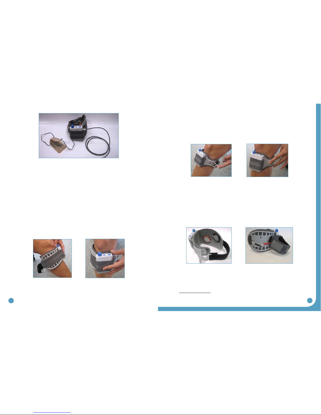
Figure 3: WalkAide Clinician Kit
14 15
2.3 Demo Kit
The Clinician Demo Kit consists of the same equipment found in the Patient Kit. However, the serial
number of the WalkAide unit is listed and tracked as a demo unit. It can be used for trial walking on
any number of patients but cannot be sold to a patient as it becomes a used medical device. (Figure 3)
2.4 WalkAide Bi-Flex Cuff
The WalkAide is designed for single-handed application and removal.It may take a bit of practice
to develop a routine that works best for each person.The WalkAide is applied directly to the leg
and can be easily worn under most clothing.The clinician will find the optimal placement of the
electrodes on the initial visit.The electrode placement will be marked on the inside of the cuff via
Red and Black Electrode Locators and the position should not be moved by the patient.
The cuff must be positioned on the leg correctly to achieve effective and efficient stimulation.Use
the Orange visual indicator as a reference for accurate placement of the cuff.Only use the latch to
secure and remove the WalkAide.TheVelcro strap is adjusted to an optimal level by your clinician at
the initial visit and should not be altered.
For proper skincare and maximum effectiveness,the electrodes should be replaced every 1 to 2
weeks or immediately upon excessive visible wear.When replacing the electrodes,be sure NOT to
alter the placement of the Black and Red Electrode Locators.
Disconnect the black and red leads between the WalkAide and the electrodes then remove the
electrodes from the Electrode Locator.Place new electrodes on the Electrode Locators and feed
the leads through the holes toward the outside of the cuff.The BLACK lead is connected to the
electrode on the BLACK Electrode Locator.The RED lead is connected to the electrode on the RED
Electrode Locator.Feed the excess wires in the strap pouch as indicated in the image below.
Washing Instructions: To wash theWalkAide Cuff fabric liner;first remove the electrodes,and
then remove the liner from the cuff. Do NOT remove the Black and Red Electrode Locators.Make
sure to Hand Wash,do not use bleach and line dry only.
Sizing Note for Clinicians: To achieve the minimum size,the strap can be folded multiple times and
secured using the double-sided Velcro provided.
Figure 4: WalkAide Patient Kit
Figure 5 Figure 6
Figure 7 Figure 8
Figure 9 Figure 10

16 17
2.5 WalkAide Cuff Disposable Liner
The purpose of the Disposable Liner is to serve as a hygienic barrier between patient trials.
Additionally,it can shorten preparation time in follow up visits. Each Disposable Liner must
be cut to fit the patient’s Cuff and the electrodes placement remains on liner for return visits.
Remember to use protective sheet over the electrodes to prevent drying.
5. Once the Electrodes’position is
determined,cut in small holes to
pass the Electrode Wires through.
(Figures 13 & 14)
2. Cut along the Cutlines
to the desired size with
Scissors for Medium and
Small.The Default size is
Large.(Figure 11)
4. Velcro dots secure the
Disposable Liner onto the
Cuff’s existing liner.The grey
fabric side of the Disposable
Liner should face out.
3. Align with the Orange
Visual Indicator on the Cuff’s
Liner.(Figure 12)
1. Write Patient Info Here.
Figure 11 Figure 12
Figure 13 Figure 14
18 19
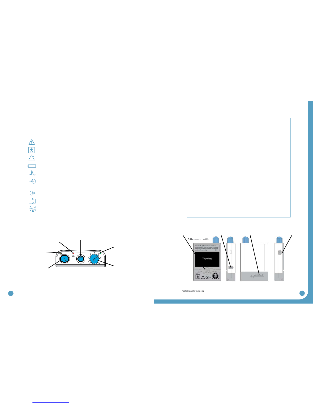
2.6 Symbols and Definitions
Meaning of Symbols
Attention, consult accompanying documents
Type BF Equipment
Indicates Error Signal
Indicates battery location and positioning
Indicates impulse, STIM button
Indicates connector location for Clinician Heel Sensor
and optional Patient Foot Sensor
Indicates input/output connector location for WalkLink
Indicates exercise button
Ionizing radiation (Wireless radio transmitter / Bluetooth)
2.7 WalkAide Controls and Indicators
Alarms:
1. Low Battery: An audible alarm of two long beeps every minute with red and green
blinking lights indicate low power condition. Change battery.
2. Heel/Foot Sensor: An audible alarm of two beeps every two seconds indicates that
Heel/Foot Sensor is not connected, when WalkAide is configured for theHeel/Foot
Sensor. Connect the heel switch or change the mode in WalkAnalyst to Hand / Tilt.
3. Device Error: An audible alarm of four beeps every two seconds with red blinking
light indicates internal fault. Resend the WalkAide Parameters to WalkAide. Turn
unit OFF, wait 5 seconds, turn back ON. Green power light should flash and red alert
gone. If red light remains on contact the distributor. (Bad program checksum)
4. Device Error: An audible alarm of three beeps every two seconds with red and
green blinking lights indicates internal fault. Resend the WalkAide Parameters to
WalkAide. Turn OFF unit, wait 5 seconds, turn back ON. Green power light should
flash and red alert gone. If red light remains on, contact the distributor. (Bad data
checksum)
5. Rapid beeping: Constant beeping with rapid green light indicates the unit was
turned on too quickly to a high level or a new battery was installed without turning
off the device. Just turn the device OFF and back ON.
6. Hibernation mode: A non-audible alarm with red blinking light indicates
hibernation mode. Establish a Bluetooth connection with WalkAnalyst to
automatically clear hibernation mode. If hibernation mode does clear, clear usage
log from standard program usage log link.
Red visual indicator for error
and low battery voltage (4)
Green blinking light indicates
that power is on with
adequate battery power (2)
Figure 15: Top view of WalkAide unit
Amber blinking
light indicates the
presence of STIM (5)
STIM Button (6) Intensity and ON/OFF Knob (1)
Exercise Button (3)
Figure 16: Back, side and front views of WalkAide unit
Output Connector
for Electrode Lead
Cable (7)
WalkLink Connector
[for clinician use only] (10)
Battery Compartment
for standard AA
alkaline battery (9)
Heel [for clinician use only]
or Foot Sensor Connector
[if provided to user] (8)
Back Left side Right sideFront

20 21
3.0 Installation of the WalkAnalyst Program
WalkAnalyst only needs to be installed once in order to run this program. Installation requires
administrator or power user rights.
1. Insert the WalkAnalyst CD or flashdrive in the appropriate drive. The PC may have an external
CD or USB Port. Make sure it is properly connected and operating correctly prior to inserting the
WalkAnalyst CD/flashdrive.
2. The installer should automatically start. Follow the set up instructions that will appear.
3. If the installer does not start automatically, find the appropriate drive icon and open the folder.
For Windows XP double click on the Setup.exe file. For Windows 7 or Vista, right click on Setup.
exe and choose Run as Administrator. Follow the set up instructions that will appear.
4.0 Set-Up Procedures for WalkLink
1. Turn ON your PC
2. Plug in your Bluetooth USB (Recommendation: use the same USB port at ALL times) see Fig 9.
3. Connect WalkAide & WalkLink, then turn ON both devices
4. Start WalkAnalyst
5. Click on Bluetooth on top-right (initial pairing only)
6. Follow Configuration Wizard (initial pairing only)
The WalkAide device sends real time data to and receives parameter changes from the
WalkAnalyst program. In order to avoid connecting a physical cable to the patient, a wireless
solution has been created employing Bluetooth radio technology. This technology allows secure
short-range communication between electronic devices.
mConfiguring initial set-up process (pairing): A link must be created from the computer to
the WalkLink. This is called the ‘pairing process’. Use the guidelines below to accomplish this
process.
4. The WalkAnalyst program will be installed in the Program Files/Innovative Neurotronics
directory unless another directory is selected.
5. Once the program has been installed, an icon will be created on the desktop for quick access.
WalkAnalyst can also be accessed from the Windows start menu. For detailed instruction,
refer to WalkAnalyst Installation& Bluetooth Configuration Guide provided with the
WalkAnalyst Software.
Note: WalkAnalyst installer will detect if Microsoft .NET framework 3.5 installed on your computer.
If approriate framework is not installed, user can find it in the WalkAnalyst installation CD/flashdrive
or Microsoft Download Center. After framework is installed, restart WalkAnalyst installation again
(step 3).
Figure 17: Front and side views of WalkLink unit
Power Indicator
WalkLink STIM button
(Hand Switch)
Low Battery Indicator
Bluetooth
Connection
Indicator
Unpair button
ON/OFF Switch
1
2
Figure 18: Flashing green light
indicates WalkLink is on Figure 19: WalkLink unpair button
Unpair button

22 23
1. Install the Bluetooth Adapter: Bluetooth adapter installation varies based on windows
operating system editions and types of Bluetooth adapters.For detailed instructions
on how to install Bluetooth adapter, refer to the WalkAnalyst Installation & Bluetooth
Configuration Guide.(Figure 20)
2. Prepare the WalkLink Device: The WalkLink device has an embedded Bluetooth
transmitter. Insert four new AA batteries in the device and turn on the power switch,
located on the upper left side. Just above the power switch,there is a recessed unpair
button.To ensure that the device is ready for initial connection, use a ball point pen
and depress this button for one second.Turn the power off, wait ten seconds and
then turn it back on.This step ensures that the device is not connected to any other
machine, and prepares the Walklink to pair itself to the current computer when
installation is complete.
3. Establish a Connection to the WalkLink Device: Start the WalkAnalyst software
by double-clicking on the WalkAnalyst icon found on the computer’s destop.
Alternatively, the WalkAnalyst program can be found at Start > Programs > Innovative
Neurotronics > WalkAnalyst. If previously connected walk link is not detected by
WalkAnalyst the software will launch in the offline mode. Press the Bluetooth
link at top right corner and Bluetooth Connection Wizard will start. (Figure 21)
If the WalkLink device is ON and ready to be configured, press OK.The WalkLink Configuration
Wizard will appear. (Figure 22)
4. Following the steps on the wizard help screen:
4.1 Turn on the WalkLink: If the WalkLink is on, the left hand LED on the face of the
device should show a flashing green light.(Figure 18)
4.2 Unpair the WalkLink: Using the tip of a ballpoint pen, press and hold the unpair
button for three to four seconds. (Figure 19)
4.3 Reset the WalkLink: To reset the WalkLink,turn the power off, wait a few seconds
and turn the power on.
Note: The computer and the WalkLink were previously connected using initial set-up
program: Turn on the WalkLink and open the WalkAnalyst software program. The blue light on
the front of the WalkLink should begin to blink. The WalkAide can be attached to the WalkLink
at any time. The blue light in the upper left hand corner of the WalkAnalyst screen will indicate
a solid connection to the WalkLink, and the green light will indicate a solid connection to the
WalkAide.
Note: Standard method will be applicable with most computers with Microsoft Bluetooth
stack properly working. Otherwise alternate pairing method should be used to pair Walk
Link with the computer using vendor provided software, such as Bluetooth Device, My
Bluetooth Place, BlueSoleil, etc.
Figure 20: Bluetooth Adapter Hardware Installed
Figure 21: Establishing a connection
Figure 22: WalkLink Configuration Wizard
Note: MAC number on page 24
24 25
mAlternate method only: Select COM Port: Make sure alternate method option is
detected. The COM Port Selection field should be displayed. (Figure 25 Alt) If it is not
displayed, press the “Show COM Port Selection”button.
Prior to the selection, establish a serial port communication link to the WalkLink in the
software provided by the bluetooth vendor (example, My Bluetooth Place, IVT/BlueSoleil
software, Bluetooth Device (Microsoft), etc). Now select the COM Port for the dropdown
and press the SAVE button. If the connection is created, the WalkLink device should now
have a blinking blue light (in addition to the green power light). (Figure 16)
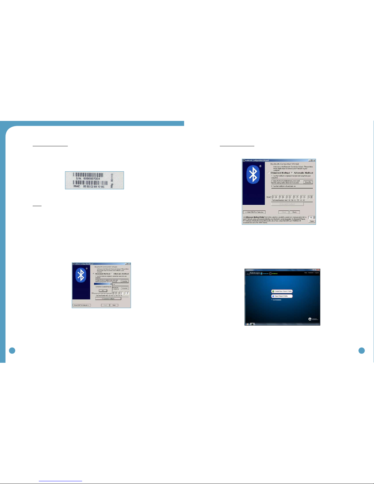
mStandard method only: Enter the WalkLink MAC Address: Make sure standard method
option is detected. Much like a street address or telephone number, each WalkLink
has an address that is used to ensure communication occurs only with that particular
device. The MAC address is located on the label on the back of the WalkLink device,
just below the serial number.
ONLY the final three numbers or letters in the MAC address are entered in the
appropriate boxes on the computer screen, as indicated by the red square in Figure 23.
mConnect: Press the button labeled“5. Connect to WalkLink” to initiate the connection
process. Progress can be tracked below the Bluetooth icon noted by the comments:
Search Underway...,Clearing Memory…, and finally Creating Connection… (Figure 24)
The wizard will try to establish a connection to a WalkLink with the address specified.
The wizard may take a minute or more to complete this process. When finished, a
confirmation message will appear. Press ‘OK’ to launch WalkAnalyst. If the connection
is created,the WalkLink device should now have a blinking blue light (in addition to the
green power light). (Figure 26)
Figure 23: WalkLink barcode label
with serial number and MAC address
Figure 24: Connect to WalkLink Process
Figure 26: Blue Light indicates Bluetooth connection
Figure 25 Alt: WalkLink Configuration Wizard

26 27
The WalkLink device is now connected. Under normal circumstances there should
be no reason to return to the wizard. If adjustments are needed in the future,the
Bluetooth connection is dropped,or WalkAnalyst is unable to find the WalkLink device,
choose the Bluetooth icon in the upper right corner of the screen. Several options
are provided, the most common of which will be to Search for Previously Connected
WalkLinks. (Figure 27)
5.0 Overview of Data Collection and Programming Process
Figure 28 outlines the process used to provide the WalkAide for a new user.
Figure 27: Search for Previously Connected Walklinks
Figure 28: Set up process for WalkAide
Pre-test Activities
Collect personal and medical
history to determine potential
candidacy for FES system.
Assess Walking Data
Assess all three walking trials
and select the trial that is most
representative of the user’s
walking pattern and of the
clinician’s effective timing with
the Hand Switch.
Find Stimulation Points
Test with peripheral nerve
stimulator.
Re-Test Stimulation
Ask user to stand and press the
Hand Switch on the WalkLink
to verify proper positioning of
electrodes and effectiveness of
stimulation intensity.
Collect Final Walking Data
Collect a final walking trial in Tilt Mode after all
initial programming and manual adjustments
have been made. Assess the effectiveness of
this final trial in providing a stim for each step
and for proper timing of the stimulation. Make
manual adjustments as necessary. Continue
to collect walking trials in tilt mode until the
pattern of stimulation is effective and safe for
the user.
Practice Walking
Ask user to walk as usual, while
clinician presses Hand Switch
on WalkLink to generate the
stimulation and address the
foot drop.
Prepare the User
Explain FES systems and
compare to conventional
mechanical interventions
Process Walking Data
Use the Zoom, Autoset and
Optimize functions to create
a unique and individual
walking program, or use Rapid
Programming
Position Electrodes and
Cuff
Determine most effective location
of electrodes and cuff to create
stimulation that provides effective
foot lift during walking.
Initiate User Set-Up
Gather all WalkAide system
equipment and supplies; confirm
Bluetooth connection and create
New File.
Attach Heel Sensor
Position Heel Sensor in user’s shoe,
connect to WalkAide and prepare to
collect load bearing data during initial
walking trials.
Record Walking Trials
Collect at least three initial
walking trials and save data for
clinical assessment.
Patient Education
Discuss the contents of the
WalkAide User Manual with
patient and sign the last page
before final delivery of the
WalkAide system.
28 29
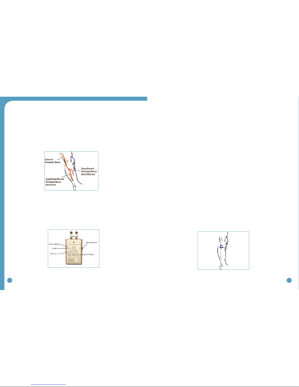
5.1 Testing with the Peripheral Nerve Stimulator
There are two primary purposes of the peripheral nerve stimulator testing procedure. The first is to
determine the viability of the common peroneal nerve and the degree of innervation of the per-
oneus longus (superficial branch) and tibialis anterior (deep branch) muscles. The second purpose is
to identify initial placement of the posterior electrode to produce a ‘balanced’ dorsiflexion and ever-
sion movement of the foot/ankle. (Figure 29)
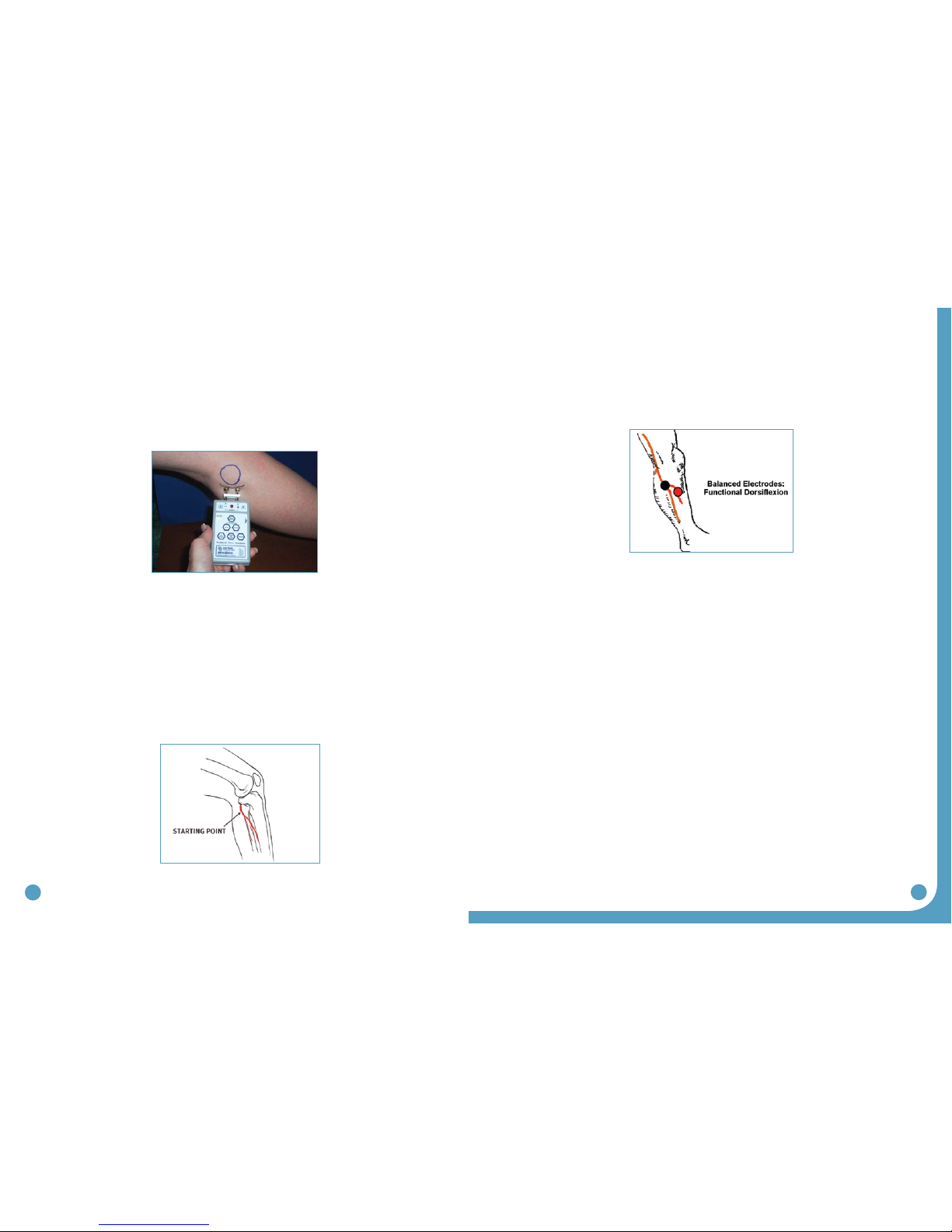
Prepare the peripheral nerve stimulator by pressing: (1) ON, (2) 50 Hz and (3) Twitch; then (4) set
the intensity dial in between 0 and 1. The orange power indicator light will be seen to indicate that
the peripheral nerve stimulator is on. (Extra 9V batteries should always be available) The red light on
the peripheral nerve stimulator will flash when a circuit between the stimulator, the nerve and the
muscle is completed. (Figure 30)
1. Always prepare the user for the testing procedure by providing a thorough explanation
of the process and always ask for continuous feedback during the procedure.
2. The user should be comfortably seated in a chair with the affected leg resting on a low stool.
The leg should be relatively extended, with just slight knee flexion to simulate the position
of the leg at terminal stance during walking, when the stimulation will be initiated. The heel
should be somewhat supported, with the foot close to a neutral alignment.
3. Clean the skin in the area around the head of the fibula with soap and water and wipe dry.
Failure to adequately prepare the skin may cause improper contact and provide less than
ideal stimulation
4. Identify (and mark) the head of the fibula. The common peroneal nerve runs posterior
and distal to the head of the fibula. (Figure 29)
• Thesuperficialbranchinnervatestheperoneuslongustoproduceeversion.
• Thedeepbranchinnervatesthetibialisanteriortoproducedorsiflexion(andinversion
in a non-weightbearing condition).
5. Wet the area around the head of the fibula generously with water. Place one hand on
the lower leg in a position to be able to feel the contraction of both the peroneus
longus and tibialis anterior muscles.
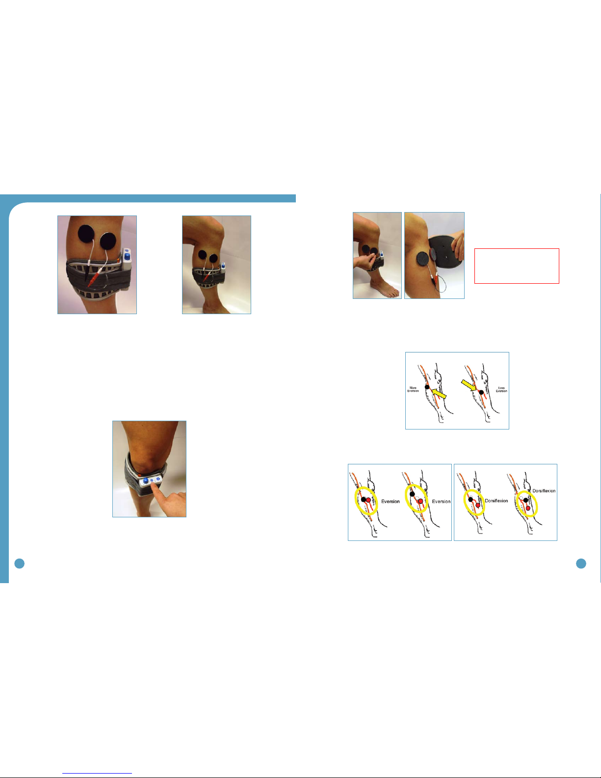
6. Identify the intersection of a line dropped vertically behind the head of the fibula and
horizontally below the head of the fibula. This is a good starting point to test for
viability of the common peroneal nerve. (Figure 31)
Figure 29: Superficial and deep branches of
the common peroneal nerve
Figure 30: Peripheral nerve stimulator Figure 31: Starting point for testing with
the peripheral nerve stimulator
30 31
7. Position the peripheral nerve stimulator against the leg so that the black-based silver
node is posterior and the red-based silver node is anterior. Press the peripheral nerve
stimulator firmly into the leg, keep the stimulator perpendicular to the leg. Gradually
turn up the intensity dial on the peripheral nerve stimulator until muscle contraction is
evidenced. Most often, this will be contraction of the peroneus longus when the
superficial branch of the common peroneal nerve is stimulated. (Figure 32)
8. Slide or shift the peripheral nerve stimulator slightly anteriorly to find the deep branch of the
common peroneal nerve and to produce a contraction of the tibialis anterior muscle. Watch
and feel for any slight twitch of the tibialis anterior muscle. Once the twitch is discovered,
stop sliding the peripheral nerve stimulator and start increasing the intensity level until a
more functional dorsiflexion movement is produced.
9. Balance the eversion and dorsiflexion movements with very slight shifting of the peripheral
nerve stimulator. After determining the most appropriate ‘balance’ point, mark the location
of the posterior black-based node on the leg. This is the starting point for placement of the
posterior electrode. (Figure 33)
The location of the branching of the common peroneal nerve varies between individuals, sometimes
splitting posterior to the head of the fibula and sometimes splitting anterior to the head of the fibula.
Slow and methodical testing of the area will identify the most appropriate starting point for place-
ment of the posterior black electrode. (Figure 34)
5.2 Electrode Placements and Final Preparations for Walking
1. Make sure the WalkAide is turned OFF and attach the electrode lead cable to the back
of the WalkAide, running the cable to the right to fit a right leg and to the left to fit a
left leg. This allows plenty of cable length to attach the electrodes and also prevents
excessive bending or flexing of the electrode lead cable.
2. Attach the WalkAide to the cuff on the medial flattened area. Position the cuff around
the mid-calf region and secure in place below the potential electrode sites. This places
the WalkAide in a convenient location to hook up the electrodes.
3. Moisten the electrode with water. Place the back electrode over the mark identified during
the testing procedure with the peripheral nerve stimulator and the front electrode on the
upper 1/3 of the tibialis anterior muscle belly. (Figure 35)
4. Connect the electrodes to the WalkAide electrode lead cable. Make sure the BLACK lead
(negative) is connected to the BACK electrode and the RED lead (positive) is connected to
the FRONT electrode. (Figure 35)
Figure 32: Initial placement of the
peripheral nerve stimulator
Figure 33: Mark the location of the posterior black based node
to identify the initial placement for the posterior electrode.
Figure 34: The goal is to produce a
functional and balanced dorsiflexion
32 33
5. Turn the WalkAide ON by turning the blue Intensity Knob in a clockwise direction to the
1 (on) position. An audible beep will sound and a green light will flash intermittently to
indicate that the unit is on. ALWAYS start at a low level of intensity and gradually increase
during the testing procedure.
6. While maintaining total contact over the electrodes with one hand, test STIM. This can be
achieved by pressing down on the large blue STIM button on the WalkAide (labeled √), the
Hand Switch on the WalkLink (if it is connected to the WalkAide and if Default Parameters
have been previously sent), or exercise mode to initiate the stimulation. (Figure 37)
7. Once the optimal electrode positions have been found, place Black & Red Markers over the
electrical (Black-Back-Red-Ahead). Turn off the WalkAide, release the cuff strap and properly
align the cuff over and around the pretibial region. (Figure 38A and 38B)
mGenerally, shifting the black electrode more posterior and proximal elicits more eversion;
and shifting the black electrode more anterior and distal elicits more dorsiflexion. (Figure 39)
Anatomical variations are common.
mAnatomical variations may include (Figure 40):
Figure 36: Placement of electrodes, cuff
and WalkAide unit for initial testing
Figure 35
Figure 37: Place unit in exercise mode
Figure 40: Final placement of electrodes relates to individual user requirements
Figure 39: In general, the posterior black electrode
determines the direction of the foot lift
Figure 38A and 38B: Carefully align the cuff over
the electrodes and secure to the leg
Helpful Hints: Electrode
placement determines patient
comfort and direction of foot
movement.

34 35
Recommendations:
m Always begin by identifying the starting point for the black electrode
m Adjust the spacing between the black and red electrodes to achieve the desired function
and contraction of muscle.
m If the contraction is not optimal initially, consider using the Exercise Mode prior to final
placement of the electrodes to “wake up” the neural pathways.
m Make small movements when shifting the electrodes to determine final electrode
placements in order to detect subtle changes in muscle contraction/function.
m Leave the electrodes on the skin until final placement is identified to prevent dissipation
of the water and to maximize user comfort. If the electrodes lose contact with the skin,
rewet and reapply.
m Evaluate functional foot movement during sitting and standing before asking the person
to walk, assuring a safe and effective foot lift for safe walking. Function can differ with
changes in patient position due to movement of the peroneal nerve.
Data Collection:
1. Place the clinician Heel Sensor in the user’s shoe on the affected side and connect its cable to
the WalkAide unit. It is best to have the patient use a firm-soled shoe and walk on a hard tile
floor during the initial data collection procedures. (Figure 41)
2. The WalkLink cable must be connected to the WalkLink unit and the WalkAide for collection
of all walking data.
3. Turn the WalkAide ON and adjust the intensity to the same level determined during initial
fitting.
4. A walking area that allows a minimum of 6 – 8 consecutive steps in walking speed is ideal for
the data collection procedures. A hard tiled floor is best for data collection but firm, low pile
carpeting is acceptable.
5. A full-length Foot Sensor is recommended for the user, it must be ordered in addition to the
Patient Kit. The Foot Sensor must be trimmed to fit appropriately inside the user’s shoe. Take
care not to damage the embedded sensor or the attached wires, and make sure the small
round disc of the Foot Sensor is properly positioned and located directly under the user’s
heel. Use of the Foot Sensor will restrict shoe wear to a closed heel shoe until the user is able
to transition to use of the Tilt Sensor.
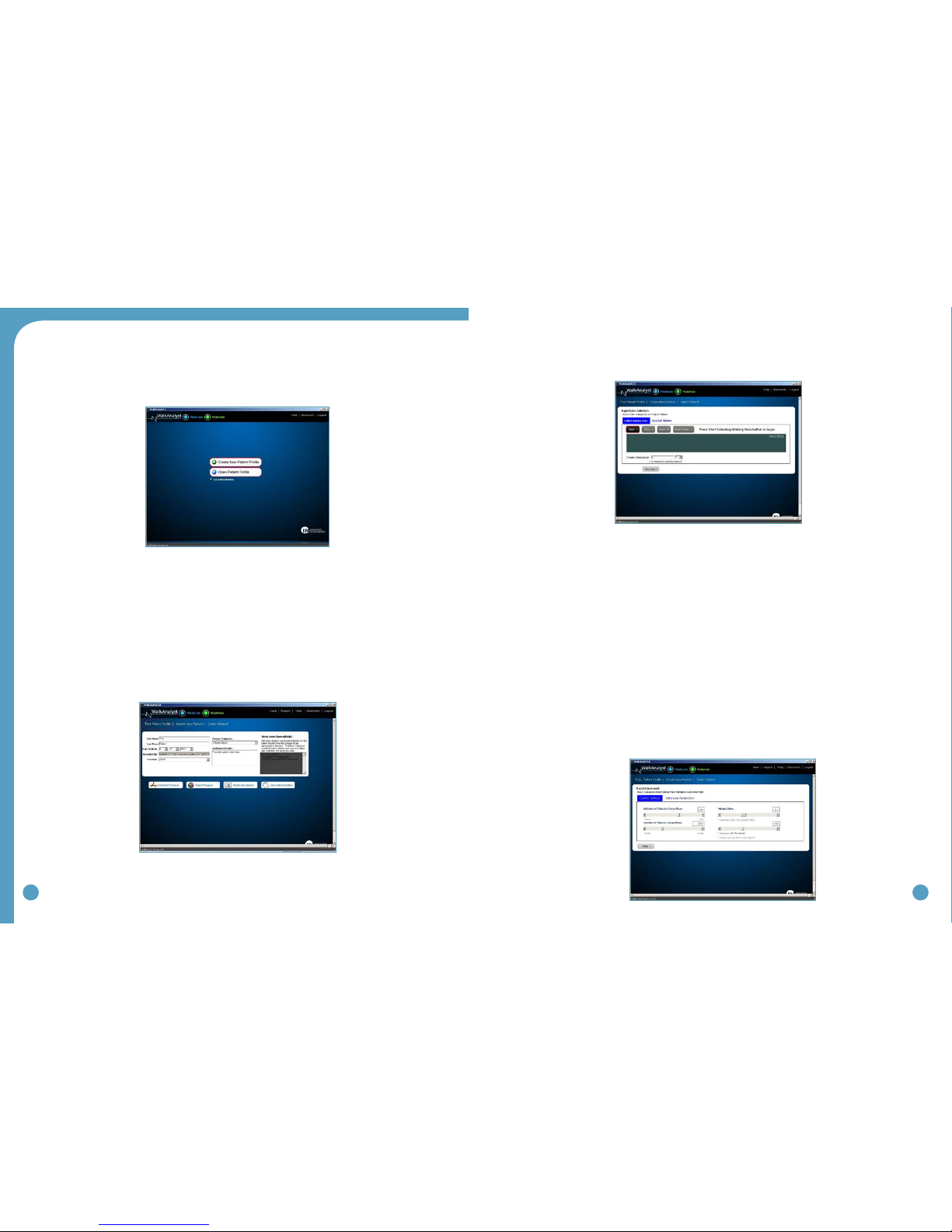
5.3 WalkAnalyst Login
Step 1: Open WalkAnalyst
Step 2: Enter username and password
• Defaultusername:wasystem
• Defaultpassword:clinician
Step 3: Select one of two Options:
• CreateNewPatientProle
• OpenPatientProle
Figure 41: Clinician heel sensor in place
and WalkLink connected
Figure 42:WalkAnalyst Login Page
36 37
Step 4: Select Programming Option
• StandardProgramming–Detailedprogrammingoptionforadvanceclinicians
• RapidProgramming–Simpleprogrammingoption
• RapidAdjustment–Allowsforsimpleadjustmentinexistingprograms
• UserAdministration–Optiontochangepasswordandaddadditionalusers.
Note: When creating a New Patient Profile,upon clicking on any of the above options,a prompt will
indicate when new file is saved.
5.4 Rapid Programming
Step 1: Pressing the Rapid Program button initiates Rapid Programming. Rapid Data
Collection option defaults to collect data in hand mode.
You will be prompted to clear your usage log.If the WalkAide unit is brand new,
clearing the log is recommended. This sets the timer of the WalkAide; Clears
hibernation mode. If you are using a demo unit you can select no.
Easy Gait Option: Option to change the Data Collection options from Hand default to Heel or to
adjust stimulation Comfort level (Recommended for Pediatric or sensitive patients)
Step 2: CollectWalking Data. Click Start and begin collecting walking data. Upon
completion, click Stop.
Zoom:Select your desired walking data by holding Left-click and dragging the
mouse arrow.Upon releasing the Left-clicking you will hear 2 beeps signalling
programming.
Enter zoom distance if the corresponding zoom distance is known;This will calculate
patient’s walking speed. Press Next Step button will send programmed parameter
to WalkAide. WalkAide will operate in till stimulous.
Step 3: Turn on beep on stim and have patient walk with the newly programmed
parameters. Adjust the control parameters based on clinical observation and patient
feedback.
Figure 43:WalkAnalyst Patient Profile Options
Figure 44:Programming Options
Figure 45:Rapid Programming Data Collection
Figure 46:Rapid Adjustment page
Other manuals for WalkAide
1
Table of contents


