Refer to the instructions manual before
installing and using this device.
WARNING: Incorrect installation, adjustment,
replacement, service or maintenance may
result in material damages, injury or death.
Read installation, operation, and
maintenance instructions before installing or
servicing this equipment.
WARNINGS
Installation, modifications and maintenance of
the appliance must be carried out by authorised
personnel in compliance with current safety
standarts.
The manufacturer declines all responsibility for
failure to comply with these obligations.
The instructions contained in this manual give
important regarding security for installing and
maintaining the appliance. The manufacturer
recommends that this manual be carefully stored
in the work zone where it can be consulted by
technicians and workers.
Gas connection of the appliance must be
according to the instructions given in table “T1”.
Disrespect of the instruction given by producer
with the appliance (Use, maintenance, gas
connectin, technical data table and data plate)
may compromise the appliance safety and will
result in immediate loss of the warranty. The
manufacturer declines all responsibility for injury
or damage to persons or things, due to disrespect
of the instructions.
INSTALLATION
Positioning
The appliance should be placed under an exhaust
hood to remove smoke and smell which may
occur during the cooking process.
Position the appliance at least 10 cm from
surrounding walls. This distance may be reduced
if the walls are flameproof or protected by
insulating material.
Assembly
The appliance should be placed on a flat surface
by balancing it due to its four adjustable feet.
Remove the protective nylon on the appliance. If
sticky particles left on the appliance, clean them
with a suitable solvent.
In the case of cantilever installations, refer to the
corresponding instructions.
Joining appliances together in line (Fig. 1)
Place the appliances side by side and level to the
same height.
Join the appliances by use of the special fixing
holes on the side of the fryer.
GAS CONNECTION
The appliance should be connected to gas source
by means of metal pipes with suitable diameter.
A suitable valve should be placed before the
appliance to stop gas flow.
After all connections have been completed, any
probable gas leakage should be controlled.
Confirm that the appliance is suitable for the type
of gas with which it will be supplied. If not, read
the paragraph "Modification for other type of
gas".
All pieces needed for montage will be supplied by
manufacturing company.
Gas flex and gas hose connections must be carried
out in accordance with TS EN 14800 standard.
MODIFICATION FOR OTHER TYPE OF
GAS
The appliance has been adjusted to operate with
20mbar NG(G20). If the appliance will be
operated with any other gas type, the following
steps should be considered.
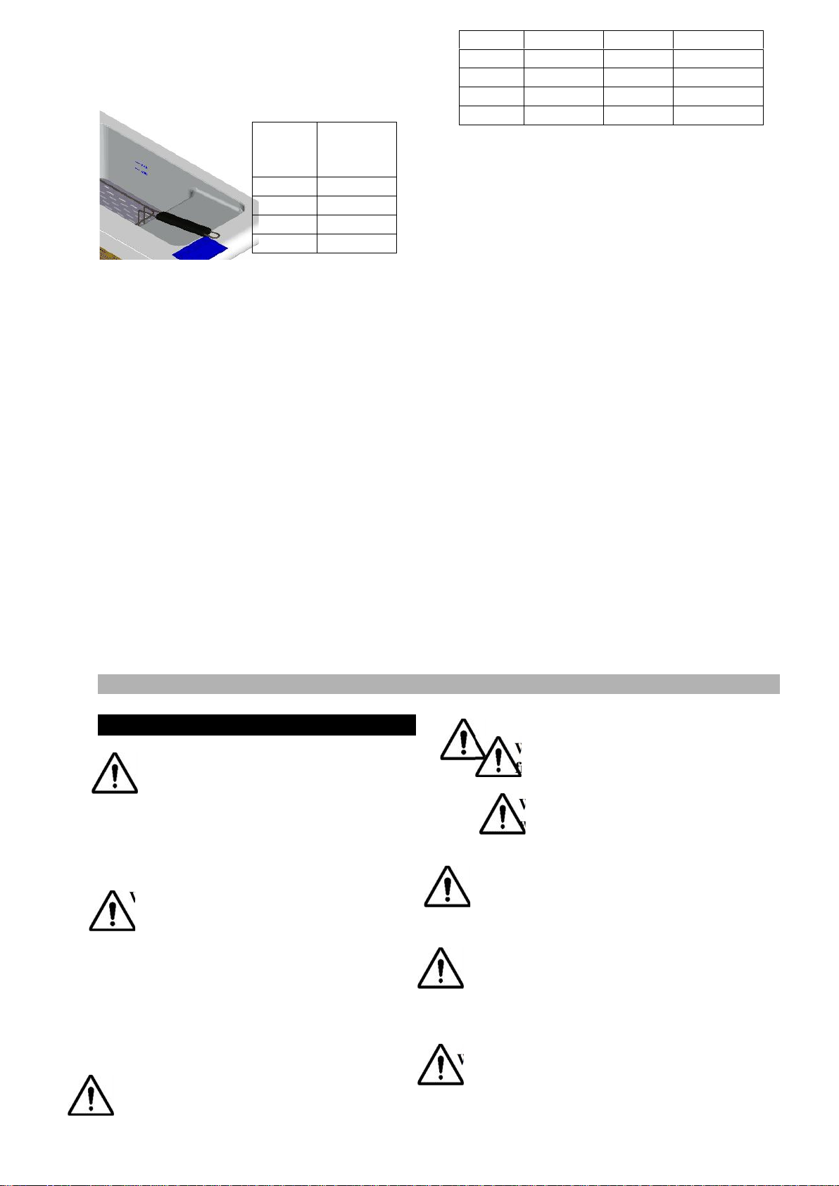
Replacement of burner injector (Figure-2)
Remove the front panel from the appliance.
Unscrew the injector “A” from injector
connection part “C”.
Choose a suitable injector indicated in table “T2”.
Screw the new injector to injector connection part
“B”.
Adjustment of air supply (Figure.2)
• Remove the front panel of the device.
• Turn on the main burner and turn the gas control
knob to the "max. Flame" position.
• Loosen screw "C" hareket and move the injector
fitting "B" ileri back and forth according to the
type of gas to ensure an ideal combustion of the
gas flame.
Replacement of pilot burner injector(Fig-3)
Remove the front panel.
Unscrew the connector "A" and substitute the
injector “B” with that indicated in table “T2”.
Screw in the connector "B".
Adjustment of Main Burner (Figure-4)
Ignite the burner and set the control button to
stage "5".
The burner should operate at the highest stage for
15 minutes then set the button to stage "1". The
flame should be observed while setting the button
from "5" to "1". If the burner extinguishes or the
flame is higher than the normal output, "C" button