8
1. AÇIKLAMA
• Bu kılavuzdaki talimatlar makinanın emniyetli
montajı, kullanımı, temizliği ve bakımı hakkında
önemli bilgiler içerir. Bu nedenle kılavuzu, makinayı
kullanacak kişi ve teknisyenin rahatlıkla ulaşabileceği
bir yerde saklayınız.
• Makinanın montajı, farklı gaz grupları için
dönüşümlerin yapılması ve bakım işlemleri bu
konuda yetkili uzman bir kişi tarafından üretici
firmanın talimatlarına uygun bir şekilde yapılmalıdır.
• Makinanın gaz bağlantısı “Teknik Özellikler”
tablosunda verilen değerlere uygun olarak
yapılmalıdır.
• Üretici firma; kullanım kılavuzuna uymadan yapılan
herhangi bir işlemden, yetkili teknisyenler tarafından
yapılmayan bakım veya teknik müdahalelerden
dolayı insanlara veya eşyalara karşı meydana gelen
nihai zararlardan sorumluluk kabül etmez.
2. MONTAJ
• Cihazı, koku ve duman oluşumunu önlemek için
yeterli havalandırmanın yapılabildiği bir davlumbaz
altına yerleştiriniz.
• Cihaz üzerindeki koruyucu naylonu sıyırarak
çıkarınız. Yüzey üzerinde yapışkan madde artıkları
kalırsa uygun bir çözücü ile temizleyeniz(örneğin
Henkel-Helios).
• Düzgün bir zemin üzerinde 4 adet ayarlanabilir
ayakları ayarlayarak cihazı teraziye alınız.
• Cihazın etrafında yanıcı malzeme olmamasına dikkat
edilmelidir.
3. GAZ BAĞLANTISI
• Cihazı gaz kaynağına uygun kesitli metal boru ile
bağlayınız.
• Gerekli durumlarda gazı kesmek için cihaz girişine
mutlaka bir vana konmalıdır.
• Tüm bağlantılar yapıldıktan sonra, gaz kaçak kontrolu
yapınız.
• Cihazın bağlanan gaz tipine uygun olup olmadığını
kontrol ediniz. Eğer değilse “Farklı Gazlara Çevrim”
bölümüne bakınız.
• Montaj için gerekli tüm parçalar imalatçı firma
tarafından sağlanacaktır.
• Gaz flexi veya gaz hortum bağlantıları TS EN 14800
standardına uygun şekilde yapılmalı.
4. FARKLI GAZLARA ÇEVRİM
• Cihaz 20mbar NG(G20) gazıyla çalışacak şekilde
ayarlanmıştır. Eğer farklı bir gazla çalışacaksa,
aşağıdaki işlemler yapılır :
4.1 - Ocak Brülör Memelerinin Değiştirilmesi
(Şekil-1)
• Izgarayı ve onun altındaki tablayı çıkarın.
• Brülör bağlama civatası “A” yı ve meme grubunu
brülöre bağlayan 2 adet “C” bağlama civatalarını
çıkarın.
• “B” tespit pimi yuvasından çıkıncaya kadar brülörü
kaldırarak çıkarın.
• “D” memesini dışarı çıkarın ve aşağıdaki gaz tipi ve
brülör çapına göre uygun memeyi seçin.
• Brülörü yerine yerleştirin (Bu arada “B” pimi kendi
tespit deliğine sokulur.)
• “A” ve “C” bağlama civatalarını sıkınız.
Sadece kapalı döküm için : (Şekil-2)
• Gaz kontrol düğmesini çıkararak vidaları sökün ve ön
panoyu çıkarın.
• Memeyi tutan ve “A” somununu sökün. “B”
memesini dışarı çıkarın ve aşağıdaki gaz tipi ve
brülör çapına göre uygun memeyi seçin.
4.2 - Ocak/Fırın Pilot Brülörlerinin Ayarlanması
TR
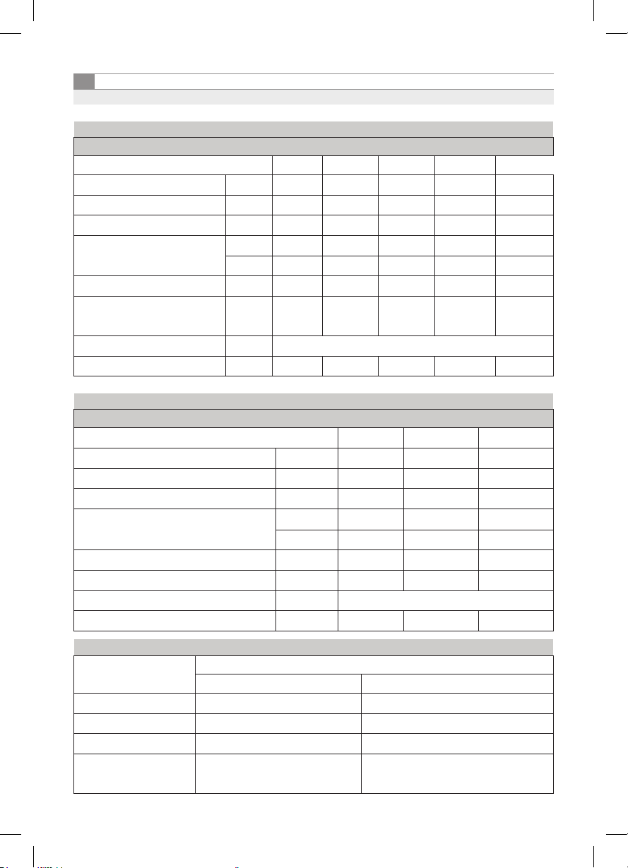
Brülör
Çapı(mm)
Meme Çapı (mm)
LPG (G30/31) Doğal Gaz (G20)
∅ 115 0,90 2,20
∅ 145 1,00 2,60
∅ 215 1,30 3,30