9
INSTALLATION
Positioning
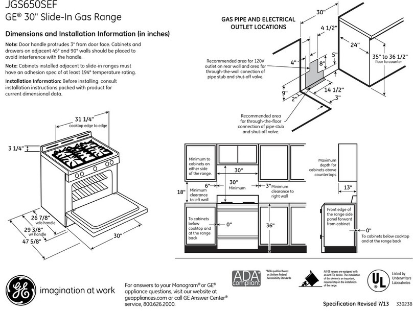
Connection and overall dimensions are given in
the pages of the appendix.
Install the appliance only in sufficiently aerated
premises.
The cookers are type "A" appliances. 'Re cooking
hot plates are type A and B11 appliances.
Position the appliance at least 10 cm from the
adjacent walls. This distance may be reduced
when the walls are incombustible or protected by
thermal insulation.
The appliance is not suitable for built-in
installation.
Assembly (Figure-1)
Remove the protective film from the external
panels. Any adhesive remaining must be removed
with a suitable solvent.
If you will use the appliance with cupboard or
oven, use reference pins to put the appliance on
cupboard/oven and set the balance of unit with
foot(4 pcs.) on flat floor.
If you will use the appliance on support leg
system, use reference pins to put the appliance on
leg system.
If you will use the appliance on working table, use
plastic foot at the bottom of appliance
Do not put any appliance on 7GF302G/GE and
9GF302G/GE model ovens.
In the case of cantilever installations, refer to the
corresponding instructions.
Joining appliances together in line (Fig. 2)
Place the appliances side by side and adjust to the
same height.
Join the appliances by use of the special fixing
holes on the side of the cooktop.
Connection to the gas supply
Before making the connection consult the gas
supplier.
Gas inlet can be made from under or behind
the appliance.
Install a fast closing stopcock in an easily
accessible position upline from the appliance.
Confirm the absence of leaks at the points of
connection.
Confirm that the appliance is suitable for the type
of gas with which it will be supplied. If not, read
the paragraph “Modification for other type of
gas”.
All pieces needed for montage will be supplied by
manufacturing company.
Gas flex and gas hose connections must be carried
out in accordance with TS EN 14800 standard.
MODIFICATION FOR OTHER TYPE OF
GAS
1. Closed Casting models (Figure-2)
Remove the screws by removing the gas control
knob and remove the front panel.
Unscrew and remove the "7" injector from the "8"
injector connecting piece.
Select the new injector suitable for the gas to be
used referring to Table"T1", and fasten to the "8"
injector adapter.
2. For closed burner models
Remove the front panel of the device.
Kindle the main burner and adjust the gas control
knob to "max. flame "
Loosen the screw "C" and ensure ideal
combustion of the flame according to the type of
gas by sliding the "B" sleeve back and forth
according to the type of gas
After the burner burned a few minutes on max.,
adjust control knob to the "min. flames" position.
Meanwhile, the burner should be in a constant
burning.
If the burner flame goes out or it is too
high, in this case low settings must be entered
with the "VM" adjustment screws on gas tap.
(Figure -3)
Flame Features
Well-mixed flame should have a stable inner cone
at its base, should appear in a dark sky blue
colour. Unless the flame gets better weather, the
flame will be yellow and veined. Flame
containing excess air will have short, transparent
and rising internal conical.
If arranged, make sure that no presence of
flashback of flame is available in both hot and
cold burners while burner is running
WARNING: If a different gas conversion has
been done in the equipment, affix an adhesive
label suitable for the gas used on a place of the
device to be seen.
SETTING UP
Control of operation of gas devices
Operation the appliance in accordance with the
instructions for use, check the correct lighting of
the burners, cheek the appliance for gas leaks and
make sure the gas exhaust system functions
correctly.
If necessary, consult the " Typical Malfunctions"
below.
