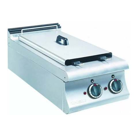
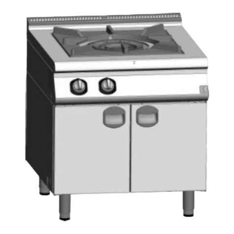
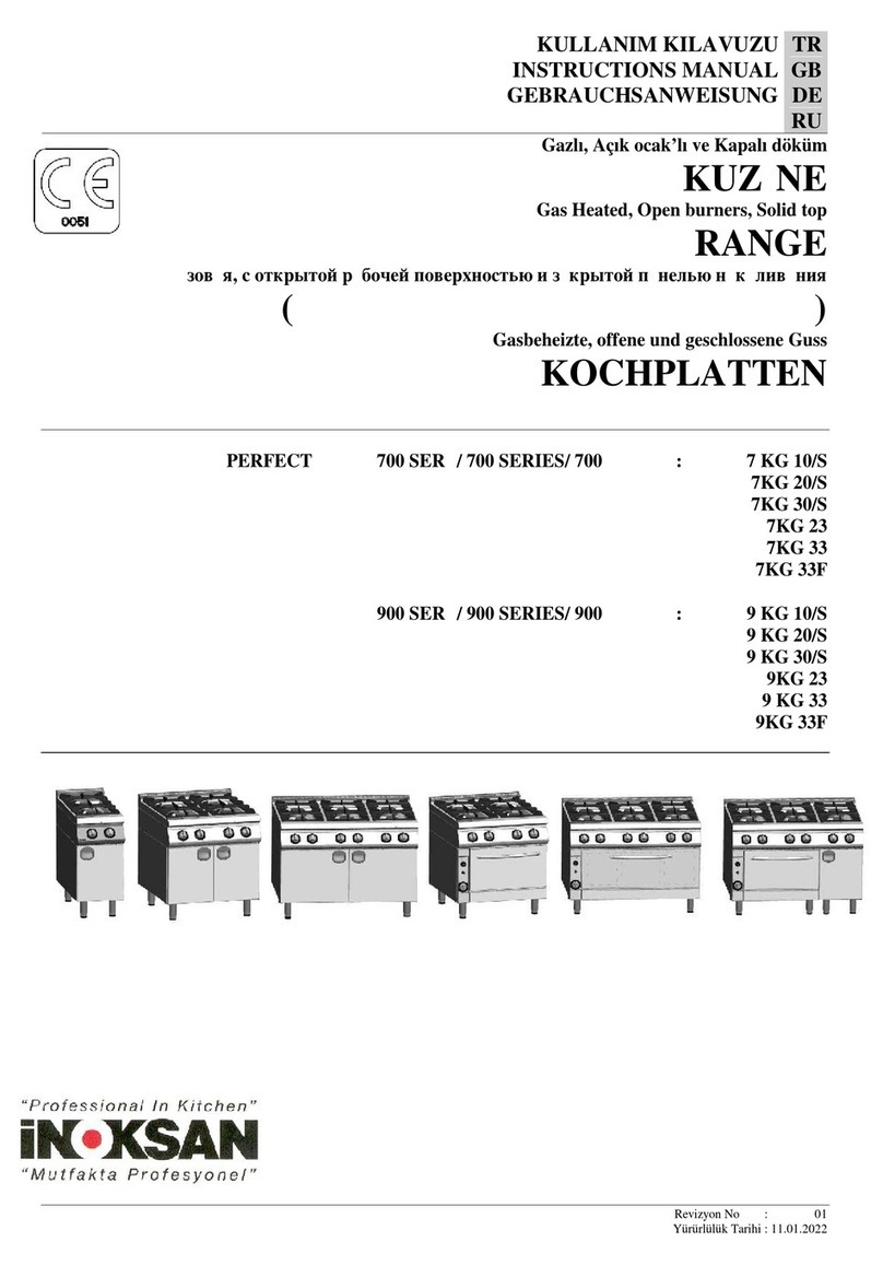
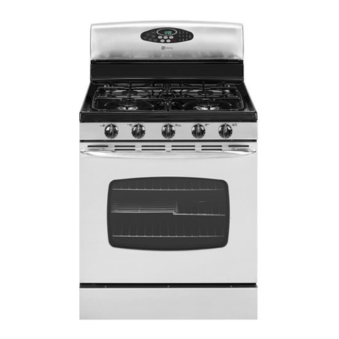
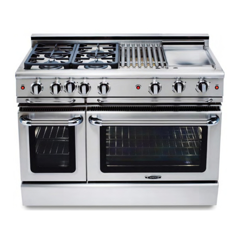
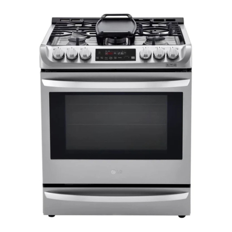
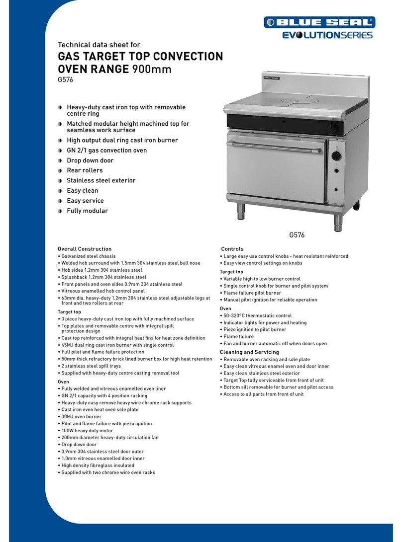
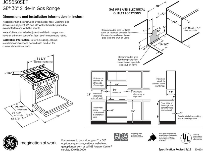
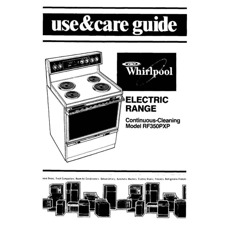
Inoksan PERFECT 7KG201 Series User manual

KULLANIM KILAVUZU
INSTRUCTIONS MANUAL
РУКОВОДСТВО ПО ЭКСПЛУАТАЦИИ
GEBRAUCHSANWEISUNG
TR
GB
RU
DE
Gazlı, Açık ocak’lı ve Kapalı döküm
KUZİNE
Gas Heated, Open burners, Solid top
RANGE
Газовая, с открытой рабочей поверхностью и закрытой панелью накаливания
ПЛИТА (ЖАРОЧНАЯ ПОВЕРХНОСТЬ)
Gasbeheizte, offene und geschlossene Guss
Kochplatten
PERFECT 7-9 KG21
Revizyon No : 00
Yürürlülük Tarihi : 07.03.2018

2

3
Şekil-1 / Figure-1
Şekil-2 / Figure-2

4
Şekil 3 – Figure 3
TEKNİK ÖZELLİKLER / TECHNICAL DATA
700-900 SERİ KUZİNELER / 700-900 SERIE RANGES
MODEL
7KG201*
9KG201*
Genişlik / Width
800
800
800
Derinlik / Depth
730
900
730
Yükseklik / Height
230
230
230
Brülör / Burner
1
1
2 2
130
130
75 100
Isı Kapasitesi / Heat Capacity
17
17
19
Enjektör Çapı Ø(mm)
2,25
2,25
1,50 2,10
0,90 1,30
Gaz Girişi / Gas Inlet
Inch
3/4"
Net Ağırlık / Net Weight
Kg
74
90
*: Kapalı Döküm modeller / Solid top models
T1
Ülke / Country
Gaz
Gas
Basınç
Pressure
Enjektör / Nozzle
Açık döküm / Open burner
Kapalı döküm
Solid top
Fırın
Oven
mbar
mm
Ø75
Ø100
Ø130
Ø130
8 kW
AT, ES, IT, BE
FI, PT, CH, FR
SE, DE, GB, LU
DK, IE, GR, TR
G20
G20
20
20
Brülör enjektörü*
Pilot enjektörü**
1,38
0,40
1,90
0,40
2,30
0,40
2,00
0,40
2,10
0,40
DK, IE, LU, ES
IT, GR, FI, NO
NL, FR, PT, GB
SE, TR, HU
G30/31
G30
G31
28-30/37
28-30
28-30
Brülör enjektörü*
Pilot enjektörü**
0,93
0,22
1,20
0,22
1,50
0,22
1,30
0,22
1,40
0,22
AT, CH, DE,
HU
G30
G31
30
37
Brülör enjektörü*
Pilot enjektörü**
0,82
0,22
1,05
0,22
1,30
0,22
1,16
0,22
1,25
0,22
* : Burner nozzle ** : Pilot burner nozzle
V
M

5
T2
Gaz
Gas
Basınç
Pressure
(mbar)
Açık döküm
Open burners
Kapalı döküm
Solid top
Fırın
Oven
Ø75
Ø100
Ø130
Ø130
Qn
kW
3,5
6
9
7
8
G20
20
Gaz tüketimi
Gas consumption
m3/h
0,37
0,64
0,95
0,74
0,85
G30
28-30
Kg/h
0,28
0,48
0,70
0,55
0,63
T3
MODEL
Σ Qn
Gaz tüketimi /
Gas consumption
kW
G20
G30
G31
m3/h
Kg/h
7KG100
9,5
1,01
0,76
0,93
7KG200
19
2,02
1,52
1,86
7KG300
28,5
1,01
0,76
0,93
7KG200 + 7GF200G *
27
2,87
2,15
2,63
7KG300 + 7GF300G *
36,5
3,88
2,91
3,56
9KG100
15
1,59
1,18
1,44
9KG200
30
3,18
2,36
2,88
9KG300
45
4,77
3,54
4,32
9KG200 + 9GF200G *
38
4,03
2,99
3,65
9KG300 + 9GF300G *
53
5,62
4,17
5,09
7KG201 / 9KG201
17
0,74
0,55
0,67
9KG201 + 9GF200G *
15
1,59
1,18
1,44
: Fırınlı / with oven
T4
P mbar
GAZ / GAS
G20
G30
G31
Nominal
20
29
37
Minimum
17
25
30
Maximum
25
35
45
T5
Ülke / Country
Kategori / Category
Gaz / Gas
Basınç / Pressure (mbar)
BE
I 2E+
G20
20
BE
I 3+
G30/G31
28/37
BE, GB
I 3B
G30
30
CY, IS, MT, RO
I 3B/P
G30
G31
30
CY, IS, MT, RO
I 3B/P
G30
G31
30
37
BE, GB
I 3P
G31
37
FR
II 2E+3+
G30/G31
30/37
FR
II 2E+3B/P
G20
G30
G31
20
30
37
FR
II 2E+3B/P
G20
G30
G31
20
30
37

6
PL
II 2E3P
G20
G31
20
37
DE
II 2ELL3B/P
G20
G30
G31
20
30
37
CH, CZ, ES, GB, GR, IE,
IT, PT
II 2H3+
G20
G30/G31
20
28-30/37
PT
II 2H3B
G20
G30
20
30
DK, EE, FI, GR, IE, IT, LT,
LU,LV, NO, SE, SI, SK,
RO, TR
II 2H3B/P
G20
G30
G31
20
30
37
AT, CH, CZ, GR, LU
II 2H3B/P
G20
G30
G31
20
30
37
HU
II 2H3B/P
G30
G31
30
37
HU
II 2H3B/P
G30
G31
30
37
CZ, ES, GB, GR, IE, IT, LU,
LV, PT, SI
II 2H3P
G20
G31
20
37
HU
II 2HS3B/P
G30
G31
30
37
HU
II 2HS3B/P
G30
G31
30
37
NL
II 2L3B/P
G30
G31
30
37
TR
MONTAJ TALİMATLARI
AÇIKLAMA
Bu kılavuzdaki talimatlar makinanın emniyetli
montajı, kullanımı, temizliği ve bakımı hakkında
önemli bilgiler içerir. Bu nedenle kılavuzu,
makinayı kullanacak kişi ve teknisyenin rahatlıkla
ulaşabileceği bir yerde saklayınız.
Makinanın montajı, farklı gaz grupları için
dönüşümlerin yapılması ve bakım işlemleri bu
konuda yetkili uzman bir kişi tarafından üretici
firmanın talimatlarına uygun bir şekilde
yapılmalıdır.
Makinanın gaz bağlantısı “Teknik Özellikler”
tablosunda verilen değerlere uygun olarak
yapılmalıdır.
Üretici firma; kullanım kılavuzuna uymadan
yapılan herhangi bir işlemden, yetkili
teknisyenler tarafından yapılmayan bakım
veya teknik müdahalelerden dolayı insanlara
veya eşyalara karşı meydana gelen nihai
zararlardan sorumluluk kabül etmez.
MONTAJ
Yerleştirme (Şekil-1)
Cihazı, koku ve duman oluşumunu önlemek
için yeterli havalandırmanın yapılabildiği bir
davlumbaz altına yerleştiriniz.
Cihazı, aşırı ısı artışlarını önlemek için yan ve
arka duvarlardan min. 10cm uzağa
yerleştiriniz.
Cihaz üzerindeki koruyucu naylonu sıyırarak
çıkarınız. Yüzey üzerinde yapışkan madde
artıkları kalırsa uygun bir çözücü ile
temizleyiniz (örneğin Henkel-Helios).
Cihaz eğer dolap yada fırın üzerinde
kullanılacaksa referans pimleri yardımı ile
cihazı dolap/fırın üzerine yerleştiriniz ve
düzgün bir zemin üzerinde 4 adet ayarlanabilir
dolap/fırın ayaklarını ayarlayarak teraziye
alınız.
Cihaz, alt kaide sistemi üzerinde
kullanılacaksa referans pimleri yardımı ile
cihazı alt kaide üzerine yerleştiriniz.
Cihaz eğer herhangi bir tezgah üzerinde
setüstü olarak kullanılacaksa altına mutlaka
plastik ayak takınız.
7GF302G/GE ve 9GF302G/GE model üst
tablalı fırınlar üzerine cihaz koymayınız.
Cihaz eğer diğer cihazlarla yan yana monte
edilecekse aşağıdaki talimatları takip ediniz.

7
Cihazların hat şeklinde birbirine
bağlanması (Şekil-2)
Cihazı diğer bir cihazın yanına yerleştirin ve
yüksekliğini aynı seviyede olacak şekilde
ayarlayınız.
Cihazları, üst yan tarafında bulunan bağlantı
deliklerini kullanarak birbirine bağlayınız.
Gaz Bağlantısı
Cihazın gaz bağlantısını yetkili servis
elemanına yaptırınız.
Gaz girişi, cihazın arkasından yada altından
yapılabilir.
Acil durumlarda hızlı bir şekilde gazı
kesebilmek için kolay ulaşılabilir bir yere gaz
vanası monte edilmelidir.
Tüm bağlantılar yapıldıktan sonra, bağlantı
noktalarında gaz kaçak kontrolu yapınız.
Cihazın bağlanan gaz tipine uygun olup
olmadığını kontrol ediniz. Eğer değilse "Farklı
Gazlara Çevrim" bölümüne bakınız.
Montaj için gerekli tüm parçalar imalatçı firma
tarafından sağlanacaktır.
Gaz flexi veya gaz hortum bağlantıları TS EN
14800 standardına uygun şekilde yapılmalı.
FARKLI GAZLARA ÇEVRİM
Cihaz 20mbar NG(G30) gazıyla çalışacak şekilde
ayarlanmıştır. Eğer farklı bir gazla çalışacaksa
aşağıdaki işlemler yapılmalıdır. Gerekli
enjektörler ve yapışkanlı etiketler cihazla birlikte
bir torba içinde verilmiştir.
Kapalı Döküm modellerde
Cihazın ön panelini çıkarın.
Ana brülörü yakın ve gaz kontrol düğmesini
"max. alev" konumuna alın.
"C" vidasını gevşetin ve "B" manşonunu gazın
cinsine göre ileri geri hareket ettirerek gaz
alevinin ideal yanmasını sağlayın.
"C" vidasını tekrar sıkın.
Brülör birkaç dakika max. yandıktan sonra kontrol
düğmesini "min. alev" konumuna getinin. Bu
arada brülör sabit bir yanmada olmalıdır.
Eğer brülör alevi sönerse veya çok yüksekse, bu
durumda gaz musluğu üzerindeki "VM" ayar
vidası ile düşük ayar girişi yapılmalıdır.(Şekil-3)
Alev Özellikleri
İyi karışımlı bir alev, tabanında kararlı bir iç
koniye sahip, koyu gök mavisi renginde
gözükmelidir. Alevin iyi hava alamaması
durumunda, alev sarı ve damarlı olacaktır. Fazla
hava içeren alev; kısa, şeffaf ve yükselen bir iç
koniğe sahip olacaktır.
Ayarlama yapıldığında, hem sıcak hemde soğuk
brülörlerde brülör çalıştırılırken alev geri
tepmesinin bulunmadığından emin olun.
UYARI : Eğer cihazda farklı bir gaza
dönüşüm yapıldı ise mutlaka kullanılan gaza
uygun yapışkanlı etiketi cihazın görülebilir bir
yerine yapıştırınız.
KULLANIM ÖNCESİ
Gaz tertibatının çalışmasının kontrolü
Cihazı kullanım kılavuzunu göre çalıştırın,
brülörlerin doğru olarak yandığını ve gaz
kaçaklarının olup olmadığını kontrol ediniz.
Eğer gerekirse "Olası Problemler" kısmına
bakınız.
Nominal Isıl Gücün Kontrolü
Cihazın başka bir gaza çevrim yapılması
durumunda yada herhangi bir bakım faaliyeti
sonrası ısıl gücü kontrol ediniz.
Cihazın nominal ısıl gücü "T3" tablosunda
verilmiştir.
Kullanılan gaza uygun enjektörler monte
edildiğinde ve uygun basınçta çalıştırıldığı
takdirde cihaz nominal ısı verir. Giriş basıncı
kontrolü için "Gaz giriş basıncı kontrolü" kısmını
okuyunuz.
Gaz giriş basıncı kontrolü
Gaz giriş basıncını ölçmek için minimum 0,2mbar
ölçümlü manometre kullanın.
Ocak için üst kontrol panelini ve fırın için fırın
kontrol panelini çıkarın. Basınç tutucu vidayı
sökerek manometreyi takın.
Cihaz çalışırken ölçüm yapın.
Manometreyi sökün ve Basınç tutucu vidayı
yerine takın.
UYARI : Eğer gaz giriş basıncı “T4”
tablosundaki değerler içinde değilse cihazı
kapatın ve yetkili servise haber verin.
OLASI PROBLEMLER / ÇÖZÜMLERİ
Pilot brülör ateşlemiyor yada zor ateşliyor
Gaz giriş basıncı yetersizdir.
Enjektör veya borular tıkanmıştır.
Gaz musluğu bozulmuştur.
Pilot brülör çalışma sırasında sönüyor.
Termokupl bozulmuştur, gaz musluğu bağlantısı
kopmuştur.
Gaz musluğu bozulmuştur.
Brülör ateşlemiyor yada zor ateşliyor
Gaz giriş basıncı yetersizdir.
Enjektör tıkanmıştır.
Gaz musluğu bozulmuştur.

8
YEDEK PARÇALARIN DEĞİŞTİRİLMESİ
Cihaz üzerinde yapılan her bakım/onarım faaliyeti
sonrası mutlaka gaz kaçak kontrolü yapınız.
Brülör, pilot brülör, termokupl, brülör
ateşleme parçaları
Üst kontrol paneli çıkarın, ızgaraları, brülör
kafalarını ve yağ tepsilerini çıkarın ve parçayı
yenisi ile değiştirin.
Gaz musluğu
Üst kontrol paneli çıkarın ve parçayı yenisi ile
değiştirin.
Gaz kontrol vanası, piezoelektrik ateşleme
butonu (fırın)
Dikey fırın kontrol panelini çıkarın ve parçayı
yenisi ile değiştirin.
Brülör, pilot brülör, termokupl, brülör
ateşleme parçaları (fırın)
Dikey ve alt fırın kontrol panellerini çıkarın ve
parçayı yenisi ile değiştirin.
KULLANIM VE BAKIM
TALİMATLARI
UYARILAR
Cihaz profesyonel kullanım için tasarlanmıştır ve
sadece bu konuda eğitim almış kişiler tarafından
kullanılmalıdır.
Cihaz yiyecek pişirme amacına yöneliktir, bunun
dışında herhangi bir amaç için kullanmayınız.
Cihazda herhangi bir arıza meydana gelirse gaz
giriş vanasını kapatınız.
Sadece üretici firma onaylı yetkili servis elemanı
ile kontak kurunuz ve sadece orijinal yedek parça
kullanınız.
KULLANIM
2. Kapalı döküm modellerde :
Gaz kontrol düğmesini "pilot ateşleme"
konumuna getirin. Düğmeye basın ve aynı
zamanda Ateşleme butonuna basarak pilot yanana
kadar 2-3 kıvılcım çıkmasını sağlayınız. Düğmeyi
yaklaşık 15sn. basılı tutun. Düğme bırakıldıktan
sonra, pilot yanmaya devam etmelidir. Eğer
yanmazsa tüm işlemi tekrarlayınız.
Pilotun ateşlenmesi manuel olarakta yapılabilir.
Gaz kontrol düğmesini pilot ateşleme konumunda
basılı tutarken, kapalı düküm ortasındaki diski
kaldırarak pilotu bir çakmak yardımı ile
ateşleyiniz.
Ana brülörü yakmak için, düğmeyi pilot brülörü
yakma konumundan istediğiniz alev konumuna
(min. yada max. alev) çevirin.
UYARI (Sadece kapalı döküm modeller için)
Bu cihazın özelliği üst dökümündeki sıcaklığın
farklı yayılımıdır. Platinanın ortasında sıcaklık
çok yüksek, kenarlara doğru daha azdır. Bu
nedenle, çabuk pişirme için ortada, yavaş pişirme
için kenarlarda pişirme yapılmalıdır.
Her türlü pişirme tavada veya diğer tip mutfak
kaplarında yapılmalıdır. Direkt döküm üzerinde
pişirme yapılmamalıdır.
TEMİZLEME VE BAKIM
Cihazda bakım yada temizlik faaliyetlerine
başlamadan önce gaz girişini mutlaka kapatınız.
Cihazı ılık sabunlu suya batırılmış bez ile tam
soğumadan siliniz.
Cihazın yüzeyinde çizik yapabilecek temizlik
maddelerini ve araçlarını kullanmayınız.
Gerekirse kimyasal temizleyiciler kullanınız.
Eğer cihaz uzun süre çalışmayacaksa paslanmaz
yüzeyleri vazelinleyin, ayrıca bulunduğu yeride
havalandırılmış olarak bırıkmak gerekir.
Periyodik olarak ocakları temizleyin ve yiyecek
artıklarını ocak portlarından çıkartın.
Cihazınız arızalandığı taktirde yetkili servisi
arayınız. Ehliyetsiz kişilerin cihaza müdahalesine
izin vermeyiniz.
Cihazın düzgün ve güvenilir çalışması için gaz
valflerinin belirli peryotlarla temizlenmesi ve
yağlanması yetkili servis elemanına
yaptırılmalıdır.
Fırının uzun süre verimli çalışması ve harhangi
bir bakım problemi ile karşılaşmamanız için
hergün aşağıda açıklandığı gibi temizlenmesi
gerekir.
Fırını yaklaşık 75-800C'ye kadar ısıtın.
Fırının içine, ızgaralara, fırın tabanına vs. uygun
bir yağ sökücü(köpüksüz) püskürtünüz.
Fırın kapısını kapatın ve 20-30 dk. bekleyiniz.
Daha sonra tekrar kapıyı açınız.
Fırın içinden ızgaraları çıkarıp yıkayınız
Fırın içini ılık sabunlu suya batırılmış bır sünger
ile veya uygun sıvı deterjanla temizleyip
kurulayınız.
Izgaraları yerlerine koyduktan sonra fırın içinin
daha iyi kuruması için kapısını kapatıp 2-3 dk.
çalıştırınız.

9
GB
INSTALLATION INSTRUCTIONS
CONFORMITY TO REGULATIONS
AND LAWS
The system and the installation of the equipment
must be performed in conformity with current
regulations.
WARNING
The installation, adjustment and maintenance of
the appliance must be carried out by qualified and
authorised installers, in conformity with current
safety regulations.
The manufacture declines all responsibility if this
obligation is not respected.
INSTALLATION
Positioning
Connection and overall dimensions are given in
the pages of the appendix.
Install the appliance only in sufficiently aerated
premises.
The cookers are type "A" appliances. 'Re cooking
hot plates are type A and B11 appliances.
Position the appliance at least 10 cm from the
adjacent walls. This distance may be reduced
when the walls are incombustible or protected by
thermal insulation.
The appliance is not suitable for built-in
installation.
Assembly (Figure-1)
Remove the protective film from the external
panels. Any adhesive remaining must be removed
with a suitable solvent.
If you will use the appliance with cupboard or
oven, use reference pins to put the appliance on
cupboard/oven and set the balance of unit with
foot(4 pcs.) on flat floor.
If you will use the appliance on support leg
system, use reference pins to put the appliance on
leg system.
If you will use the appliance on working table, use
plastic foot at the bottom of appliance
Do not put any appliance on 7GF302G/GE and
9GF302G/GE model ovens.
In the case of cantilever installations, refer to the
corresponding instructions.
Joining appliances together in line (Fig. 2)
Place the appliances side by side and adjust to the
same height.
Join the appliances by use of the special fixing
holes on the side of the cooktop.
Connection to the gas supply
Before making the connection consult the gas
supplier.
Gas inlet can be made from under or behind
the appliance.
Install a fast closing stopcock in an easily
accessible position upline from the appliance.
Confirm the absence of leaks at the points of
connection.
Confirm that the appliance is suitable for the type
of gas with which it will be supplied. If not, read
the paragraph “Modification for other type of
gas”.
All pieces needed for montage will be supplied by
manufacturing company.
Gas flex and gas hose connections must be carried
out in accordance with TS EN 14800 standard.
MODIFICATION FOR OTHER TYPE OF
GAS
1. Closed Casting models (Figure-2)
Remove the screws by removing the gas control
knob and remove the front panel.
Unscrew and remove the "7" injector from the "8"
injector connecting piece.
Select the new injector suitable for the gas to be
used referring to Table"T1", and fasten to the "8"
injector adapter.
2. For closed burner models
Remove the front panel of the device.
Kindle the main burner and adjust the gas control
knob to "max. flame "
Loosen the screw "C" and ensure ideal
combustion of the flame according to the type of
gas by sliding the "B" sleeve back and forth
according to the type of gas
After the burner burned a few minutes on max.,
adjust control knob to the "min. flames" position.
Meanwhile, the burner should be in a constant
burning.
If the burner flame goes out or it is too
high, in this case low settings must be entered
with the "VM" adjustment screws on gas tap.
(Figure -3)
Flame Features
Well-mixed flame should have a stable inner cone
at its base, should appear in a dark sky blue
colour. Unless the flame gets better weather, the
flame will be yellow and veined. Flame
containing excess air will have short, transparent
and rising internal conical.

10
If arranged, make sure that no presence of
flashback of flame is available in both hot and
cold burners while burner is running
WARNING: If a different gas conversion has
been done in the equipment, affix an adhesive
label suitable for the gas used on a place of the
device to be seen.
SETTING UP
Control of operation of gas devices
Operation the appliance in accordance with the
instructions for use, check the correct lighting of
the burners, cheek the appliance for gas leaks and
make sure the gas exhaust system functions
correctly.
If necessary, consult the " Typical Malfunctions"
below.
Control of nominal thermal power
The appliance's nominal heat input must always
be checked following installation and conversion
to a different gas supply, and also after servicing.
The appliance's nominal heat input is indicated in
“T3” Table.
The nominal heat input is correct when the
appliance is fitted with the appropriate injectors
for the type of gas used and the inlet pressure is as
specified in Table “T4”. To check the inlet
pressure, follow the instructions indicated in the
section "Control of gas supply pressure".
Control of gas supply pressure
To measure the gas supply pressure use a
manometer with a minimum definition of 0.2
mbar.
Remove the upper control panel(for the cooktop)
and then the oven control panel (for the oven
burners). Remove the screw “PP” on the pressure
connection and connect the manometer to it.
Ignite the burners and measure the inlet pressure.
The pressure reading must correspond with the
ratings shown in table “T4”. If not, switch off the
appliance and contact your local Gas Supply
Authority immediately.
Disconnect the manometer and retighten the
screw “PP” in pressure connection.
TYPICAL MALFUNCTIONS
Difficulty or impossibility of lighting pilot
burner
Insufficient gas supply pressure.
The gas line or injector is clogged.
The gas tap is faulty.
Pilot burner goes out during use
The thermocouple is faulty, insufficiently heated
or incorrectly connected to the gas tap.
The gas tap is faulty.
Difficulty or impossibility of pilot burner
Insufficient gas supply pressure.
The injector is clogged.
The gas tap is faulty.
Difficulty or impossibility of setting gas oven
temperature
Gas valve defective.
Thermostat defective.
REPLACEMENT OF SPARE PARTS
Always cheek for gas leaks after carrying out
maintenance work or repairs on the appliance.
Burners, Pilots, Thermocouples, Burner
lighting sparkers of cooking hob and hot plate
burners
Remove the upper control panel, grilles, burner
heads and trays and replace the component.
Gas taps, Piezoelectric lighters of cooking hob
Remove the upper control panel and replace the
component.
Gas valves, Piezoelectric lighter of gas oven
Remove the vertical control panel of the oven and
replace the component.
Burners, Pilot, Thermocouple, Burner lighting
sparker of oven
Remove the vertical and lower control panels of
the oven and replace the component.
INSTRUCTIONS FOR USE AND
MAINTENANCE
WARNINGS
This appliance is intended for professional use
and must only be used by trained personnel. This
appliance is exclusively designed to cook food.
Any other use shall be deemed improper.
The use of the steak griddle on the grilles is
permitted only on the small burners.
The installation, the modification for another type
of gas must be carried out by qualified and
authorised installers.
If the appliance breaks down, close the gas shut-
off valve upstream of the appliance.
Only contact the technical service centre
authorised by the manufacturer and only use
original spare parts.
The manufacture declines any responsibility if
these obligations are not respected.
Read this booklet with attention and keep it
carefully for the lifetime of the product. Before
using the appliance, clean carefully all surfaces
which may have contact with food.

11
OPERATION
Cooking hob and hot plate burners
The pilots of the open burners must be lit
manually (e.g. with a match).
The pilot burner of the cooking hot plate is
always equipped with piezoelectric lighting.
The control knobs of the taps of the cooking hob
have the following positions :
- Off
- Pilot Ignition
S- Minimum flame
SS - Maximum flame
Lighting cooking hob and hot plate burners
Press and turn the knob to the position.
Press the knob down fully and light the pilot (by
means of the piezoelectric lighter if fitted).
Maintain the knob pressed down for about 20
seconds, before releasing it. If the pilot goes out
repeat the operation.
Turn the knob to any position between Sand SS.
Turning off cooking hob and hot plate burners
To turn off the burner, turn the knob to position
. To turn off the pilot, press and turn the knob
to position .
IMPORTANT : (Only for hot plate models)
The main characteristic of this appliance is
uneven heat distribution on the upper cast. The
heat degree in the middle of the plate is maximum
but the heat decreases at the edges. Thus, fast
cooking can be performed at the centre of the
plate and sides of the plate are ideal for slow
cooking.
Frying pans or similar utensils should be used for
frying or cooking process. Never cook on the cast
directly.
Never pour cold liquid onto the hot plate.
CLEANING AND MAINTENANCE
Before carrying out any cleaning operation close
the gas valve.
Clean the stainless steel surfaces daily with water
and ordinary non-abrasive detergents, rinse well
and dry carefully. Do not use steel wool or
products containing chlorine.
Do not use sharp abjects which can scratch and
damage steel or coated surfaces.
Do not use corrosive products to clean the floor
under the appliance.
Do not clean the appliance with jets of water.
If the equipment will not be operated for a long
time, apply a thin layer of vaseline on the
stainless steel surfaces of the appiance and it
should stay in a properly ventilated room.
Cleaning the cookers periodically and remove the
food particles from the connection parts of the
cooker.
In case of any failure at the appliance, call the
authorized technical service. The appliance
should be examined by professional technical
staff.
The gas valves of the appliance should be cleaned
and lubricated periodically for a reliable and
regular operation of the appliance.
Cleaning the interior of the oven :
Daily cleaning of the interior of the oven avoids
maintenance problems in the future. Use a
suitable degreasing spray product (not foaming)
for cleaning even in the "hidden" zones.
Heat the oven to 75-800C.
Spray the degreasing solution throughout the
interior of the oven, on the grilles, the grille
supports and the oven floor.
Close the oven door and allow the product to
react for about 20-30 minutes.
Open the oven door carefully, paying attention to
the eyes and the skin.
Remove from the interior of the oven the grilles
and the floor and wash separately.
Clean and rinse the oven interior with a sponge
using tepid soapy water and/or normal liquid
detergents, drying afterwards.
Remount the internal parts and dry further by
turning on the heating for a few minutes.
This manual suits for next models
1
Table of contents
Languages:
Other Inoksan Range manuals

Inoksan
Inoksan PERFECT 700 Series User manual

Inoksan
Inoksan 700 Series User manual

Inoksan
Inoksan PERFECT 700 Series User manual

Inoksan
Inoksan 1KG100L/R User manual

Inoksan
Inoksan PERFECT 700 Series User manual

Inoksan
Inoksan PERFECT 9KG 21 User manual

Inoksan
Inoksan 7KE100 User manual

Inoksan
Inoksan 7 KG 10/S User manual

Inoksan
Inoksan 1KA052 User manual

Inoksan
Inoksan PERFECT 700 Series User manual