InoTec SCAMAX 2600 User manual

SCAMAX®2600/4000 Tech. Manual 06/2002 T-1
Service Manual
Document Scanner
SCAMAX®2600/4000
As at 04.06.2002 (SB)

SCAMAX®2600/4000 Tech. Manual 06/2002 T-2
Table of Contents
Technical Manual Part T
1INTRODUCTION................................................................................................................................... 4
1.1 SCANNER MODELS, OPTIONS AND ACCESSORIES .............................................................................. 4
1.2 TECHNICAL DATA ............................................................................................................................. 5
1.3 COMPLIANCE WITH REGULATIONS AND STANDARDS: .......................................................................... 6
2SYSTEM COMPONENTS..................................................................................................................... 8
2.1 SCAMAX 2600 WITH VIDEO INTERFACE ........................................................................................... 8
2.2 SCAMAX 2600 WITH SCSI INTERFACE ............................................................................................ 8
2.3 SCAMAX 2600 WITH GREYSCALE INTERFACE .................................................................................. 9
3SCANNER COMPONENTS AND FUNCTIONS................................................................................. 11
3.1 CCD-LINEAR-CAMERA ................................................................................................................... 15
3.1.1 Camera types........................................................................................................................ 17
3.1.2 Camera Faults ...................................................................................................................... 18
3.1.2.1 Changing Camera Board Type 2+3 ................................................................................................. 18
3.1.2.2 Changing Camera Board Type 0 ..................................................................................................... 19
3.1.2.3 Changing the CCD Linear Sensor ................................................................................................... 19
3.1.2.4 Camera Adjustment for SCAMAX®2600 Type 3 ............................................................................. 21
3.1.2.5 Camera Adjustment for SCAMAX®2600 Type 0. ............................................................................ 24
3.1.2.6 Camera Adjustment for SCAMAX®4000 Type 2 ............................................................................. 25
3.2 CONTROLLER-BOARD REV. B ......................................................................................................... 26
3.3 EXCHANGING THE CONTROLLER BOARD .......................................................................................... 29
3.4 DTPLUS BOARD ............................................................................................................................. 30
3.5 I/O BOARD..................................................................................................................................... 33
3.6 ULTRASOUND DOUBLE-FEED DETECTOR ......................................................................................... 35
3.7 FOOTSWITCH ................................................................................................................................. 36
3.8 ENDORSER .................................................................................................................................... 36
3.8.1 Printhead............................................................................................................................... 36
3.8.2 Photocell ............................................................................................................................... 37
3.8.3 Processor Board ................................................................................................................... 37
3.8.4 Endorser Settings ................................................................................................................. 39
3.8.4.1 Print Density for Text/Barcodes (Druckdichte/BcDichte%) .............................................................. 40
3.8.4.2 Character Distance (CharAbstand) .................................................................................................. 41
3.8.4.3 Thickness for Text/Barcodes (Fettdruck/BcFettdruck) ..................................................................... 42
3.8.4.4 Barcode Lines Ratio (BcBalkenVerh.) .............................................................................................42
3.8.4.5 Endorser Counter (PagiNummerH/L)............................................................................................... 43
3.8.4.6 Time & Date (Zeit Datum) ................................................................................................................ 43
3.8.4.7 Print Position Time (KopfStbyZeit)................................................................................................... 43
3.8.4.8 Cleaning the Print Head (Kopfreinigung) .........................................................................................43
3.8.4.9 Print Head Voltage (InkHead Spng)................................................................................................. 44
3.8.5 Change Endorser Settings.................................................................................................... 44
3.9 POWER SUPPLY ............................................................................................................................. 47
3.9.1 Mains Power Switch Unit ...................................................................................................... 47
3.9.2 Mains Transformer................................................................................................................ 48
3.9.3 Switching Power Supply ....................................................................................................... 48
3.10 LAMP UNIT ................................................................................................................................. 50
3.10.1 Rectifier Board ...................................................................................................................... 50
3.10.2 Electronic Lamp Ballasts ...................................................................................................... 50
3.10.3 Fluorescent Lamps ...............................................................................................................50
3.11 OPERATOR PANEL ...................................................................................................................... 51
3.12 OPTICAL COMPONENTS UNIT....................................................................................................... 53
3.13 PAPER TRANSPORT .................................................................................................................... 54
3.13.1 Input Hopper with Drive Motor .............................................................................................. 54
3.13.2 Diagnosing Paper Input Hopper Faults ................................................................................ 57
3.13.2.1 General Faults ................................................................................................................................. 57

SCAMAX®2600/4000 Tech. Manual 06/2002 T-3
3.13.2.2 Condition dependent Faults with GAL 2.2 ....................................................................................... 58
3.13.2.3 Condition dependent Faults with GAL 2.3 ....................................................................................... 59
3.13.3 Paper Feed with Separation System .................................................................................... 60
3.13.4 Rubber Roller Pairs (two) ..................................................................................................... 63
3.13.5 Paper Output Path ................................................................................................................ 63
3.13.6 Output Hopper ...................................................................................................................... 64
3.13.7 Drive Mechanism with Stepper Motor................................................................................... 65
3.14 DESCRIPTION OF SCAN ROUTINE FLOW ....................................................................................... 68
Spare Parts List Part E
Service Program Part S

SCAMAX®2600/4000 Tech. Manual 06/2002 T-4
1 INTRODUCTION
The SCAMAX 2600 is a bitonal document scanner. It is designed to be used in document conversion
projects of medium volume requiring medium speed. The scanner is driven from a PC connected to it.
This PC also receives the scanned images and processes them further as required.
The SCAMAX 4000 is a colour document scanner. It is identical in construction to the SCAMAX 2600 ,
except that it is equipped with a colour camera.
1.1 Scanner Models, Options and Accessories
The scanners are currently available in the following Models:
Description Part Number
SCAMAX 2600 Simplex Video, B/W with one scan unit for single sided
scanning and video interface
s2600010
SCAMAX 2600 Duplex Video, B/W with two scan units for double sided
scanning and video interface
s2600020
SCAMAX 2600 Simplex SCSI, B/W with one scan unit for single sided
scanning and SCSI interface
s2600030
SCAMAX 2600 Duplex SCSI, B/W with two scan units for double sided
scanning and SCSI interface
s2600040
SCAMAX 4000 Simplex Video, Colour with one scan unit for single sided
scanning and video interface
s4000010
SCAMAX 2600 Duplex Video, Colour with two scan units for double sided
scanning and video interface
s4000020
Options:
Greyscale interface (SCAMAX 2600 only)
8 Bit; 256 Greyscales
s0000055
DTplus-Board (SCAMAX 2600 only)
To scan difficult, low contrast documents
s0000500/1
Endorser
Prints text, numbers or dates on backside of documents
s2600200
Acid resistant paper rollers
For self-carbonising (impregnated) paper
s2500130
Accessories:
Purpose built work desk s0000055
Optical Filter #60 green (SCAMAX 2600 only) s9000030
Optical Filter #40 red/orange (SCAMAX 2600 only) s9000021
Optical Filter #90 red (SCAMAX 2600 only) s9000020
Optical Filter #81 blue (SCAMAX 2600 only) s9000010
Feeder extension for A3 documents s2500122
Foot Switch (Paper separation On/Off) s9000100
Anti-Static Brush for output hopper s2500125
SCSI-Cable (50 Pin) high density s9020100
SCSI-Cable (68 Pin) high density s9020110
White Calibration Paper (10 sheets) s9100000
Cleaning Kit s9100010
Vacuum Cleaner s9100020

SCAMAX®2600/4000 Tech. Manual 06/2002 T-5
1.2 Technical Data
- Scanner type: CCD array camera
- Number of scan units:
- 1 scan unit for single sided scanning
- 2 scan units for simultaneous scanning of front and back page
- Resolutions: 200, 240 (SCAMAX2600 only), 300 and 400 dpi
- Document widths: 26 mm - 320 mm
- Document lengths: from 60 mm upward
- Document thickness: various, can be set for each stack or single sheet
- Document feed: automatic from stack or single sheet hand feed
- Stack height: max. 50 mm
- Double Feed Detection: document length check and ultrasound sensor
- Video Port out to PC: V24, video digital, bitonal
optional: video with 256 greyscales (8 bit greyscale)
with
- Control Port to PC: serial, 9 pin, RS232
or:
- SCSI 2 Port to PC: 50 pin, high density
with
- serial interface to service PC
- Binarisation method:
- Standard unit 1. with fixed threshold
and
2. with one-dimensional auto-threshold
- with Dtplus board: with two-dimensional auto-threshold

SCAMAX®2600/4000 Tech. Manual 06/2002 T-6
- Scan speed (at 200 dpi resolution):
- A4 portrait:
- 75 sheets per minute (simplex)
150 pages per minute (duplex)
- A4 landscape:
- 90 sheets per minute (simplex)
180 pages per minute (duplex)
- Electrical requirements:
230 V, 50 Hz, 1,0 A
115 V, 60 Hz, 2,0 A
- Dimensions (width, height, depth):
510 mm, 365 mm, 650 mm
- Weight: 39 kg
- Endorser: the optionally fitted endorser
facilitates printing of free-dorm text, date, time and sequence number
on the back of documents
- Environmental requirements:
- room temperature: 10° to 35°C.
- relative humidity: 30% to 80% without condensation
- Noise level: less than 70 dB
1.3 Compliance with Regulations and Standards:
The scanners Scanner SCAMAX 2600/4000 comply with the regulations and standards that form the
basis of the CE compliance declaration that follows:

SCAMAX®2600/4000 Tech. Manual 06/2002 T-7
SCAMAX®2600/4000 Tech. Manual 06/2002 T-8
2 SYSTEM COMPONENTS
2.1 SCAMAX 2600 with video interface
Documents are illuminated and scanned inside the SCAMAX 2600. The picture information is digitised
and then sent to the external PC as an 8-bit parallel bitonal video signal for each side (front and back
respectively) via the video interface. Compression, image manipulation and storage 9in TIFF-G4 format
takes place in the PC.
Scan module 1 is used to scan the front of each document.
Scan module 2 (present in the duplex scanner model) is used to scan the back of each document.
For difficult documents, like handwriting or coloured paper with low contrast, a DTplus board can be
installed for each scan module. This enhances image quality greatly.
Image information is transmitted digital bitonal (black&white) from the scanner’s video interface to the
video board (f. ex. HISCAN or dunord board) in the scan PC. A separate control cable for communication
purposes is fitted.
The PC’s scan controls the video board via appropriate drivers, which in turn controls the scanner.
2.2 SCAMAX 2600 with SCSI interface
In a SCAMAX 2600 with SCSI interface the bitonal image data and all commands are transmitted via a
SCSI cable.
The scan PC must be fitted with a SCSI controller (f.ex. ADAPTEC 2940 AU). The scan application
(client) controls the scanner via the Twain or ISIS driver supplied.
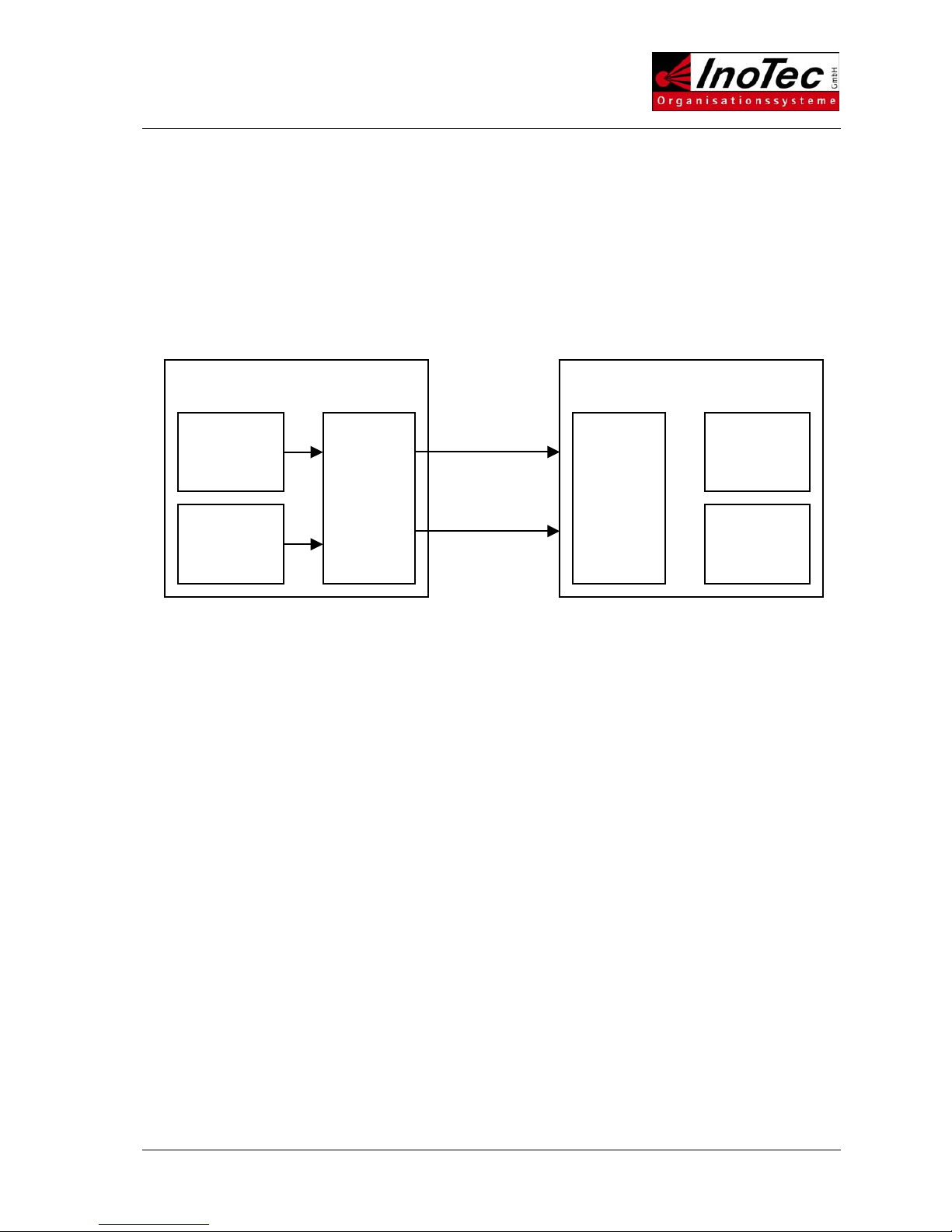
Scanner S26/S40 Scan PC
Scanner
module 1
Controller
Board
&
Video-
interface
Scanner
module 2
Scanner
Interface
Driver
Application
Video
V 24
8 bit
p
arallel
SCAMAX®2600/4000 Tech. Manual 06/2002 T-9
It is possible to control the SCAMAX 2600 via SCSI commands without using the Twain or ISIS driver.
Since the command set of the SCSI interface is by and large compatible with other manufacturers it is
relatively easy to generate a generic driver without great programming effort.
2.3 SCAMAX 2600 with Greyscale interface
For special application the SCAMAX 2600 can be fitted with a greyscale interface. The greyscale
interface passes image information in 8-bit form (256 grey levels) to the scan PC.
Scanner
module
front page
Scanner
module
reverse
page
Grey scale
interface
Controller
Board
Output video
8 bit grey scale
front page
Output video
8 bit grey scale
reverse page
8 bit
grey scale
8 bit
grey scale
8 bit
grey scale
8 bit
grey scale
Output
video bitonal
front page
Output
video bitonal
reverse page
Scanner S26/S40 Scan PC
Scanner
module 1
SMART
SCSI
Interface
Scanner
module 2
SCSI
Controller
TWAIN
or ISIS
Driver
Application

SCAMAX®2600/4000 Tech. Manual 06/2002 T-10
The scan module for the front page of the document transmits the image information in 8-bit format, i.e.
with 256 grey levels.
In the case of a duplex scanner the scan module for the back page simultaneously transmits the image
information in 256 grey levels as well.
The greyscale interface passes the greyscale image information for the front and back page via a
separate port to the scan PC.
At the same time the same image information is passed to the controller board. It converts the images to
bitonal (black&white) format for the front and back respectively and transmits it separately to the scan PC.
As can be seen in the drawing, one port each for bitonal and greyscale output exists for the front page.
These are connected to the PC’s scanner interface (dunord-Board). For the back page identical twin ports
exist. These are connected to the second scanner interface in the PC.
If the SCAMAX 2600 has a DTplus-Board fitted for each scan module that board comes with an
integrated greyscale interface. Should greyscale images be required it is possible to fit a plug connection
on each board (special option) to lead to outside port to transmit the greyscale signal to the PC.

SCAMAX®2600/4000 Tech. Manual 06/2002 T-11
3 SCANNER COMPONENTS AND FUNCTIONS
The SCAMAX 2600/4000 scanner consists of the following main elements:
The paper transport system – it pulls sheets of paper into the scanner, transports them through the
machine and deposits them in the output hopper. It consists of input hopper, which is adjustable for single
sheet feed or stack feed, paper separation unit, transport mechanism and output hopper.
The illumination unit.
The optical system consisting of two mirrors plus a lens with colour filter.
The scan module 1, scanning the front of each document, is present in all SCAMAX scanners.
The scan module 2, scanning the back of each document, is only found in duplex models.
The controller board – controls all process in the machine.
The I/O board – converts TTL signals from the controller board into the signals required by the various
‚users’, such as motors. It also converts outputs from sensors, such as photocells and switches, into TTL
signals.
The operator panel – facilitates basic operation of the scanner, except for scan commands and internal
settings.
The power supply unit – supplies the necessary voltages for the entire machine.
The ultrasound double feed detector.
Optionally fitted elements are:
One DTplus board for each scan module, which significantly enhance images from difficult documents.
The greyscale interface.
The endorser - consisting of printer unit, endorser board and photocell. Used to print date, time, and so
on onto the back of each document during the scan process.
The following page shows a cross section of the SCAMAX 2600/4000 document scanner:

SCAMAX®2600/4000 Tech. Manual 06/2002 T-12

SCAMAX®2600/4000 Tech. Manual 06/2002 T-13
The principal of operation is as follows:
A single sheet or a stack of documents is placed in the input hopper. A photocell detects the presence of
document/s.
When the scan PC issues a scan command the machine pulls in the single sheet or top sheet of the stack
via the feed roller. The sheet travels through two guide plates till a rubber roller pair grips it. The sheet
reaches the scan area and is then grabbed by a second pair of rubber rollers. Subsequently, the sheet is
transport around a guide plate by yellow transport belts upwards and forward till it is deposited into the
output hopper.
In the scan area the sheet is illuminated by one or two fluorescent lamps, simplex or duplex. The lamps
are offset to each other to minimise ‚print-through’. The light reflected from each side of the sheet
contains the image information for the front and back respectively. Since the sheet is in continuous
motion each line is scanned in succession.
The reflected light hits a mirror that projects the light to a second mirror. The second mirror projects the
light to the lens, which sits in front of the CCD array.
The CCD converts the light containing the image information into an analogue electrical signal, which is
digitised and possibly binarised in the next processing step before being transferred to the PC.
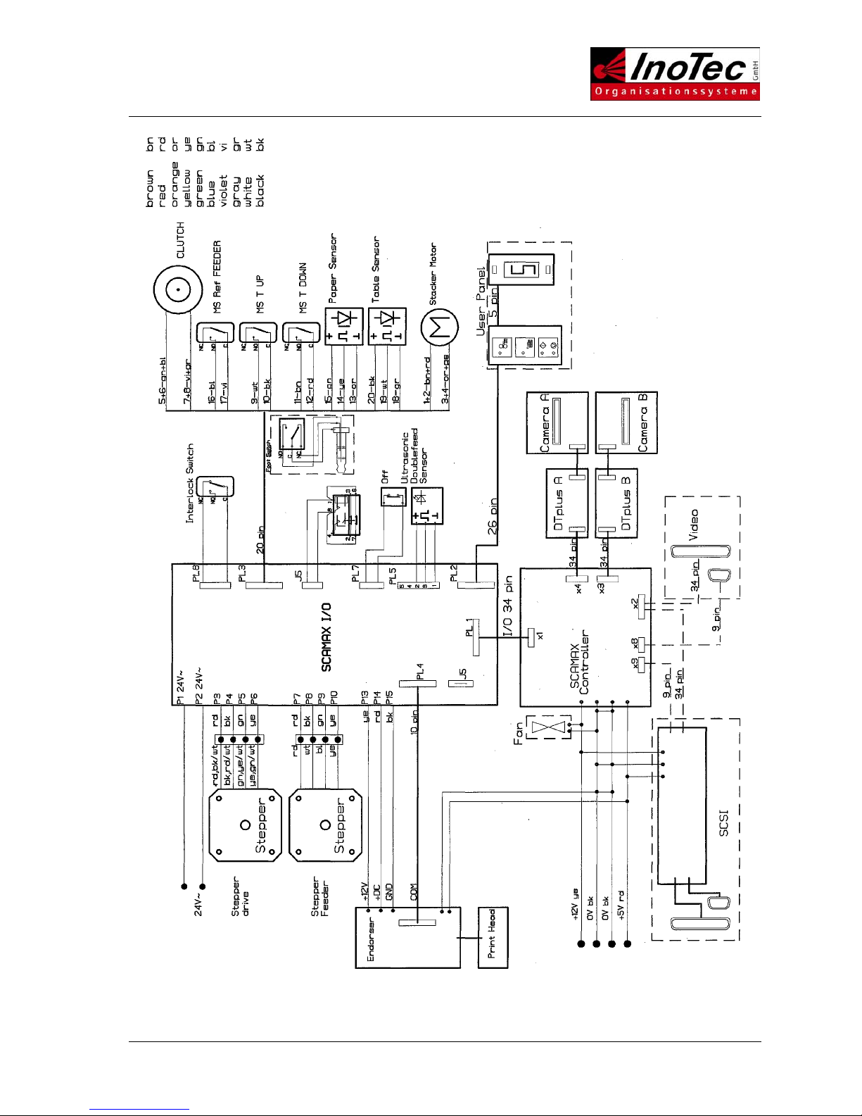
The following page shows an electrical block diagram:
SCAMAX®2600/4000 Tech. Manual 06/2002 T-14
SCAMAX®2600/4000 Tech. Manual 06/2002 T-15
3.1 CCD-Linear-Camera
The CCD linear camera consists of a lens unit mounted on an aluminium plate and a CCD linear sensor
with associated electronics components fixed in a metal housing, which is attached to the aluminium
plate.
The document to be scanned is illuminated in the scan area. The CCD linear sensor captures the
reflected light containing the image information, after it has been refracted by two mirrors and passed
through the lens.
CCD stands for Charge Coupled Device. It is an electronic component containing capacitor elements
arranged in parallel. The capacitors convert the amount of light received into electrical current, the voltage
generated being proportional to the amount of light detected. An analogue-to-digital converter translates
the charge for each pixel into an 8-bit digital value.
This process takes place at very high speed, the clock speed being 20 MHz. This means that each
second an enormous amount of image information is read and output, i.e. 20 megapixels for bitonal and
60 megapixels for colour (20 for each channel red, green, blue).
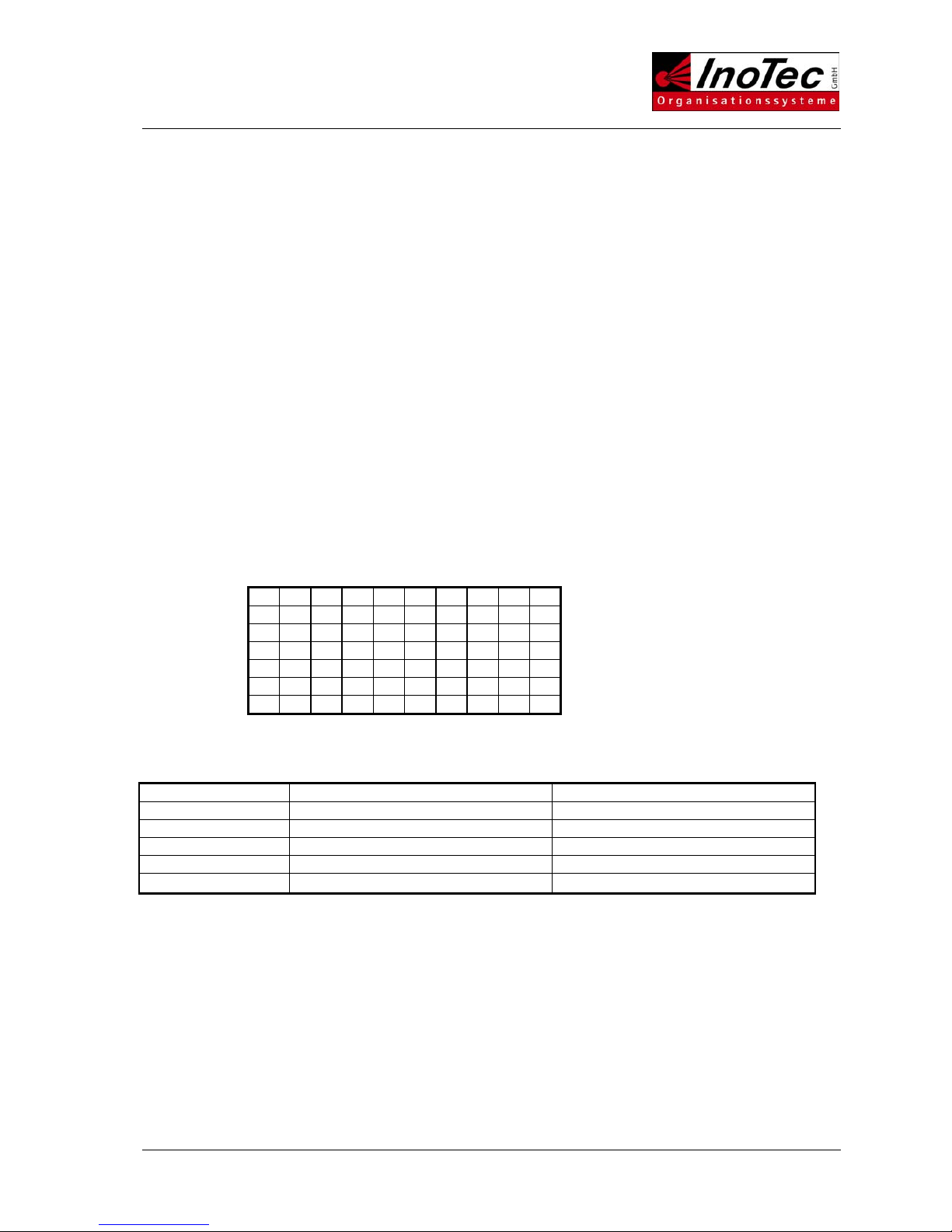
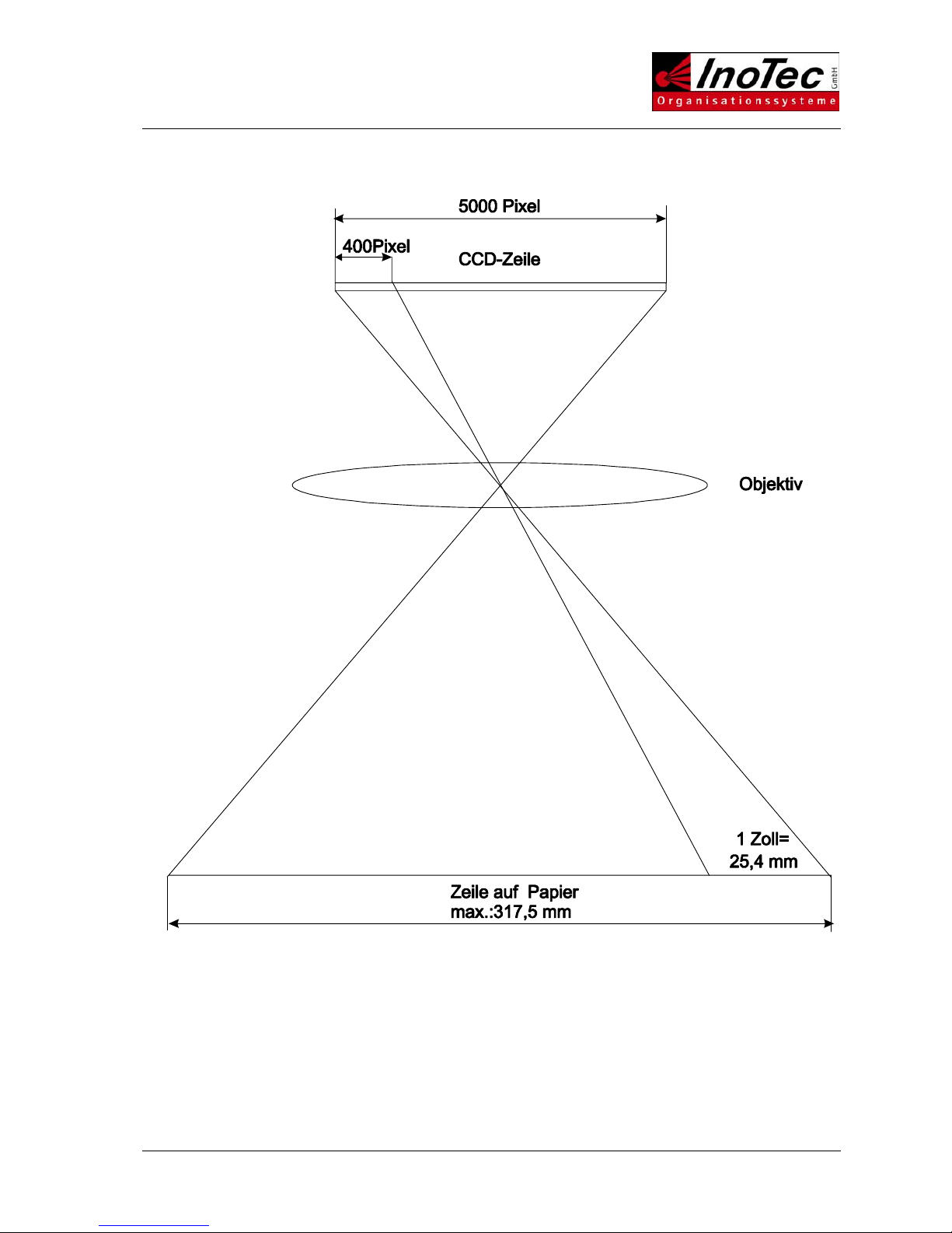
The CCD used has 5000 light sensitive pixel elements. This number is sufficient to scan an A4 page in
portrait mode (3,700 pixel) or an A3 in portrait mode (4,670 pixel) at an optical resolution of 400 dpi (dots
per inch).
It is necessary to set the optical reduction in such a way that a width of 1 inch (25.4 mm) covers exactly
400 pixels on the CCD chip (see illustration next page).
For lower resolutions the pixel elements shown in the table below are deactivated:
400 dpi X X X X X X X X X X
300 dpi X X X X X X X X
240 dpi X X X X X X
200 dpi X X X X X
The scan speed (paper transport speed) is automatically adjusted according to the resolution selected.
200 dpi requires only half the number of lines, thus the paper can be transported at double the speed.
SCAMAX 2600 SCAMAX 4000
Resolution in dpi Paper transport speed in m/min. Paper transport speed in m/min.
200 29,3 27,5
240 24,4 X
300 19,6 18,3
400 14,7 13,8
SCAMAX®2600/4000 Tech. Manual 06/2002 T-16
Illustration of optical reduction

SCAMAX®2600/4000 Tech. Manual 06/2002 T-17
The reading of the CCD linear sensor and conversion into digital values described above takes place on
two channels. One channel each for odd and even pixels. With colour two channels are used for each
colour.
A shielded ribbon cable is connected to the CCD board (two for colour), which provides the connection to
the controller board and for colour also to the video interface.
Both mechanical and electronic adjustments are accomplished by using the service program.
3.1.1 Camera types
Two different types of CCD linear cameras are used for the SCAMAX®2600/4000 scanners.
SCAMAX®2600:B&W CCD linear camera Type 0
B&W CCD linear camera Type 3
SCAMAX®4000: Colour CCD linear camera Type 2
CCD linear camera Type 0
CCD linear camera Type 3 CCD linear camera Type 2

SCAMAX®2600/4000 Tech. Manual 06/2002 T-18
3.1.2 Camera Faults
The service program is used to determine whether a camera is faulty. The program can display the
camera status. If the camera status is shown as OK it is possible that the camera sends wrong data or no
data at all. This fact would be shown by an unexpected curve formation, heavy noise or absence of a
channel. If a problem is diagnosed it will not be immediately obvious whether it is caused by the camera
board and/or the CCD sensor. Therefore, several solutions present themselves. In the majority of cases
an exchange of the camera board will yield the result desired. This methodology has the advantage of
retaining the optical alignment of the camera.
3.1.2.1 Changing Camera Board Type 2+3
Switch off Scanner!
All activities have to undertaken in accordance with current ESD regulations!
Remove the two screws of the EMV camera housing and lift lid.
Pull the post connector from the board (1x for SCAMAX®2600 and 2x for SCAMAX®4000) and un-screw
the four plastic nuts.
Using a pair of pliers pull the board backwards out of the housing by the earth straps. Ensure the board is
pulled squarely out of the housing; otherwise the CCD sensor's contact pins will be bent.
Carefully insert the new board and fasten using the plastic nuts.
Front Back
Camera-EMV-Housin
g
Earth straps Plastic nuts

SCAMAX®2600/4000 Tech. Manual 06/2002 T-19
Replace the post connector and switch the scanner on. The next step is to set CCD sample delay, which
calculates and adjusts run time differences of the various components, using the service program. To set
the CCD sample delay insert a sheet of white calibration paper in portrait mode into the scanner and
transport it past the roller pair. Press the "D" key and follow the menu instructions. When finished insert
the sheet in landscape mode and perform a white calibration ("M" key).
If the service program's camera signal display does not show an improvement re-insert the original
camera board and exchange the CCD sensor as described under 1.1.2.3 instead.
3.1.2.2 Changing Camera Board Type 0
The difference to the procedure described under 1.1.2.1 is that the camera type 0 has two boards
mounted on top of each other. The board having the potentiometers is mounted on the CCD board, it can
simply be pulled off. The CCD board is fastened with four nuts (M3) and have to be unscrewed prior to
removal of the board. When fitting the new boards ensure that they sit squarely one on top of the other.
The camera signals are to be adjusted as described under 1.1.2.5.
3.1.2.3 Changing the CCD Linear Sensor
All activities have to undertaken in accordance with current ESD regulations!
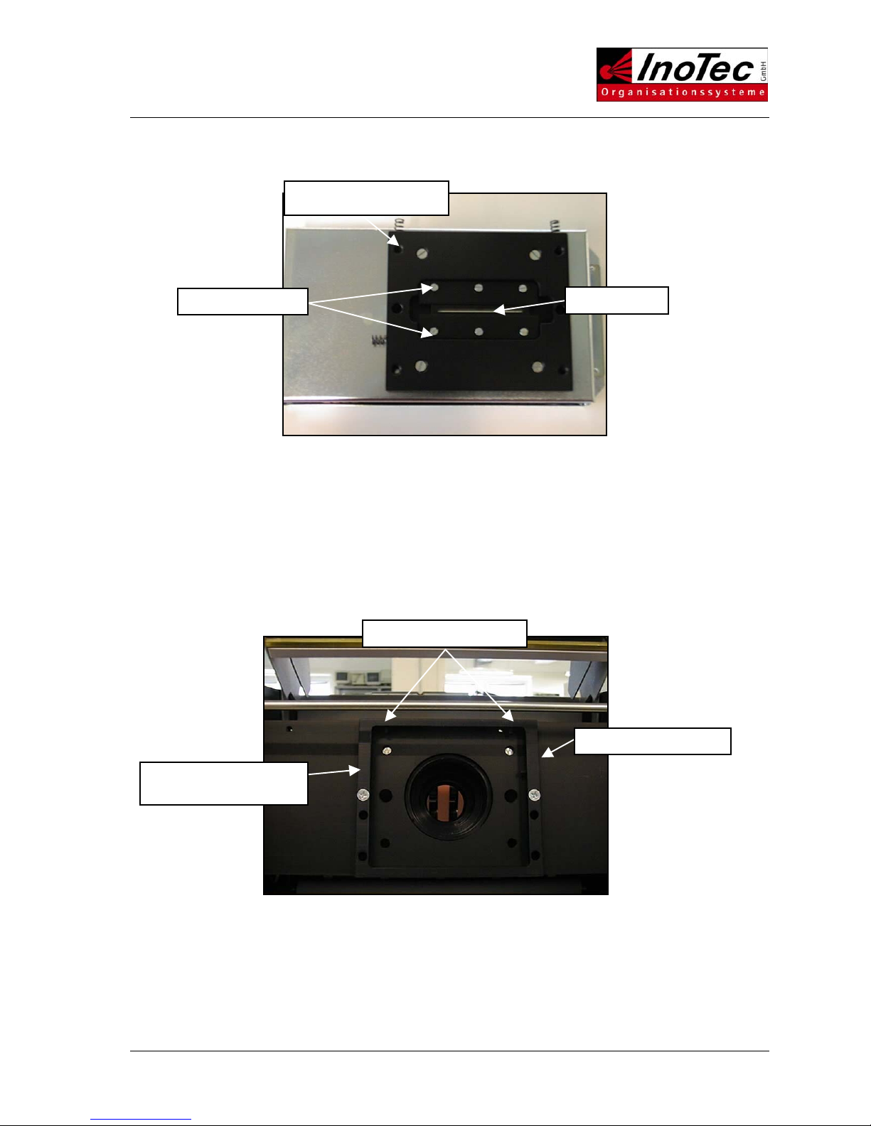
To change the CCD sensor it is necessary to remove the entire camera unit (consisting of: board. EMV
housing, board mounting plate and CCD sensor) from the scanner. Unscrew the fixing bolts (M4x10) and
remove the EMV housing with board mounting plate.
Front
Fixing bolts
Back
SCAMAX®2600/4000 Tech. Manual 06/2002 T-20
Unscrew the IC support plates and mark the position of the CCD sensor on the board mounting plate.
Plug the new CCD sensor into the IC socket on the board and align to the previously marked position.
CAUTION! Check polarity.
Fasten IC support plates. The new CCD sensor must be absolutely free from dust and grease. Clean it.
Insert the complete camera unit into the adjustment frame, ensuring the springs are forward. Check that
springs are not bent. Compress the springs sufficiently to ensure the board mounting plate seats properly
behind the set-screws. Fasten fixing bolts, then undo them again a quarter of a turn. The camera should
now be movable within the adjustment frame.
Set-screw ( C )
Set-screws (A+B)
Camera adjustment
frame
CCD sensor
Board mounting plate
IC support plates
This manual suits for next models
1
Table of contents
Other InoTec Scanner manuals


Popular Scanner manuals by other brands


Colortrac
Colortrac SMARTLF SCAN User instructions

Canon
Canon imageFORMULA DR-1210C Brochure & specs

Brother
Brother DS-620 user guide

Fujitsu
Fujitsu ScanSnap iScanner fi-6010N Cleaning instructions

Scanivalve
Scanivalve DSA3217-PTP Series Operation and service manual

Microtek
Microtek ScanMaker V6USL installation guide