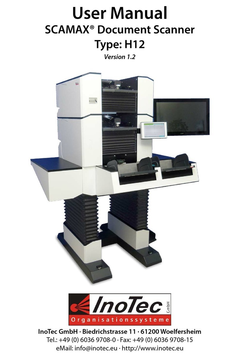
InoTec SCAMAX H12 User manual

User Manual
SCAMAX® Document Scanner
Type: H12
Version 2019.12
InoTec GmbH .Biedrichstrasse 11 .61200 Woelfersheim
Tel.: +49 (0) 6036 9708-0 .Fax: +49 (0) 6036 9708-15
eMail: info@inotec.eu .http://www.inotec.eu

Table of Contents User Manual H12 / SCAMAX® 8x1 - Version 2019.12
Page 2 of 136
Table of Contents
1. Introduction..........................................................11
1.1. Safety instructions .................................................11
1.2. Specic Danger Spots...............................................11
1.2.1. Unmarked Danger Spots ......................................11
1.2.1.1. Covers ..............................................11
1.2.1.2. Dust Exposure .......................................12
1.2.1.3. Dual Input Hopper ...................................12
1.2.1.4. Input tray ...........................................12
1.2.2. Marked Danger Spots ........................................12
1.2.2.1. General Danger Spot .................................12
1.2.2.2. Danger Spot Seize/Entangle ...........................13
1.2.2.3. Danger Spot Crush/Jam 1 .............................13
1.2.2.4. Danger Spot Crush/Jam 2 .............................14
1.2.2.5. Danger Spot Crush/Jam 3 .............................14
1.2.2.6. Danger Spot Electrical Voltage .........................14
2. General description ..................................................15
2.1. SCAMAX® upgrade concept 801/811/821 ..............................16
2.2. Extensions/options .................................................16
2.2.1. Dual Input Hopper ...........................................16
2.2.2. HighSpeed Stacker Arm ......................................16
2.2.3. 2nd Output Hopper ..........................................16
2.2.4. Imprinter HD ................................................16
2.2.5. Straight Through Paper Path Elevation ..........................17
2.2.6. Extension kits for over-sized documents ........................17
2.3. Device Views ......................................................18
2.3.1. Front Views .................................................18
2.3.1.1. Basic Model .........................................18
2.3.1.2. Expansion Stage (Dual Input Hopper / 2nd Output Hopper) ......19
2.3.2. Rear View ...................................................19
2.3.3. Interior Scan Plane ...........................................20
2.3.4. View Imprinter ..............................................20
3. Startup Operation ....................................................21
3.1. Scope of Delivery ..................................................21

Table of Contents User Manual H12 / SCAMAX® 8x1 - Version 2019.12
Page 3 of 136
3.2. Setting Up the Device...............................................22
3.3. Relocating the unit .................................................22
3.4. Connecting the Device ..............................................22
3.4.1. Power Supply / Main Switch ...................................23
3.4.2. USB3 Port for Scan Jobs.......................................23
3.4.3. USB Ports for Input Devices or Data Storage .....................23
3.4.4. Network Connection for Batch Transfer .........................23
3.4.5. Connecting the External Image Display (optional) ................24
3.5. Switching the Device On and O / Initialization After Start ...............24
3.6. Installation of Drivers ...............................................25
3.6.1. USB Device Driver............................................25
3.6.2. TWAIN™ Driver ..............................................25
3.6.3. ISIS-compatible Driver (MS61) .................................26
4. Capacitive Touchscreen...............................................27
4.1. Division of the Display Surface .......................................27
4.1.1. Status ......................................................27
4.1.2. User........................................................27
4.1.3. Info ........................................................28
4.1.4. Navigation Bar ..............................................28
4.1.5. Display Area ................................................28
4.1.6. Tool Bar ....................................................28
4.2. Operation Methods.................................................29
4.2.1. Input Fields .................................................29
4.2.2. Color Picker Dialog ...........................................30
4.2.3. Event List ...................................................31
4.3. Scan Processing....................................................32
4.3.1. Division of Scan Screen .......................................32
4.3.1.1. Stream Information. . . . . . . . . . . . . . . . . . . . . . . . . . . . . . . . . . . 32
4.3.1.2. Sheet Information ....................................32
4.3.1.3. Output Information ..................................33
4.3.1.4. Counter Information..................................33
4.3.1.5. Button Bar ..........................................33
4.3.1.5.1. Modifying Quick-Access Buttons .............33
4.3.2. Job and Prole Selection ......................................34
4.4. User Settings ......................................................35

Table of Contents User Manual H12 / SCAMAX® 8x1 - Version 2019.12
Page 4 of 136
4.5. Job Management (Administrator Rights required!)..........................36
4.5.1. General ....................................................37
4.5.2. Prole Selection .............................................37
4.5.3. Counters ...................................................37
4.5.4. Index File ...................................................38
4.6. Prole Management (Administrator Rights required!)........................39
4.6.1. General.....................................................40
4.6.1.1. Privilege Level .......................................40
4.6.1.2. Access Function Buttons ..............................40
4.6.1.3. Quick-Access Buttons .................................40
4.6.2. Image ......................................................42
4.6.2.1. Image Presettings ...................................42
4.6.2.1.1. Enable Moiré Filter .........................42
4.6.2.1.2. Gamma Correction .........................43
4.6.2.1.3. White Background .........................43
4.6.2.1.4. Add/Remove Borders .......................43
4.6.2.1.5. Resize Image ..............................44
4.6.2.2. Color Dropout .......................................44
4.6.2.2.1. Separate Channel...........................44
4.6.2.2.2. Dropout Setting 1-3.........................45
4.6.2.2.3. Fill Color ..................................46
4.6.2.2.4. Dropout at ................................46
4.6.2.3. Resolution ..........................................46
4.6.2.4. Delete Image(s) at ....................................47
4.6.2.5. Front/Rear Side Settings ..............................47
4.6.2.5.1. Color .....................................47
4.6.2.5.2. Gray ......................................49
4.6.2.5.3. Bitonal ...................................49
4.6.2.5.4. Stream Control ............................52
4.6.2.5.5. Blank Page Detection .......................55
4.6.3. Input/Output ...............................................56
4.6.3.1. Paper...............................................56
4.6.3.1.1. Format Selection ...........................56
4.6.3.1.2. Paper Path Elevation ........................57
4.6.3.2. Input ...............................................57
4.6.3.2.1. Feeder Mode ..............................58
4.6.3.2.2. Separation ................................58
4.6.3.2.3. Feeder Capacity ............................58
4.6.3.2.4. Camera Threshold ..........................58
4.6.3.3. Output .............................................58
4.6.3.3.1. Switch Out1/Out2 at ........................59
4.6.3.3.2. Output to Tray 1/2 at .......................59

Table of Contents User Manual H12 / SCAMAX® 8x1 - Version 2019.12
Page 5 of 136
4.6.3.3.3. Current Output to Tray 1/Tray 2/Rear at ........59
4.6.3.3.4. Next Output to Tray 1/Tray 2/Rear at ..........59
4.6.3.3.5. Switch Front/Rear at ........................59
4.6.3.4. Orientation .........................................60
4.6.3.4.1. Paper Input Orientation .....................60
4.6.3.4.2. Output Image Orientation ...................60
4.6.3.4.3. Additional Back Orientation..................60
4.6.3.4.4. Text Orientation ...........................60
4.6.3.5. Deskew ............................................61
4.6.3.5.1. Edge Threshold ............................61
4.6.3.5.2. Deskew Fill Color ...........................61
4.6.3.5.3. Advanced Settings..........................61
4.6.4. Scanner ....................................................62
4.6.4.1. Double Feed Detection ...............................62
4.6.4.1.1. Activate/Deactivate.........................62
4.6.4.1.2. Stop at Input...............................63
4.6.4.1.3. Reaction at Detection .......................63
4.6.4.1.4. Show DF Images ...........................63
4.6.4.1.5. Continue after Delete .......................63
4.6.4.1.6. Sensor Conguration .......................64
4.6.4.2. Control Settings .....................................64
4.6.4.2.1. Scan Speed ................................65
4.6.4.2.2. Use High Speed Stacker Arm .................65
4.6.4.2.3. Output Hopper Sensor Range ................65
4.6.4.2.4. Input Hopper Down ........................65
4.6.4.2.5. Sheet Not Valid until Output .................65
4.6.4.2.6. Scan Pause at ..............................66
4.6.4.2.7. Shorter Than/Longer Than ...................66
4.6.4.2.8. Optimized Gap/Additional Feeding Gap .......66
4.6.4.2.9. Manual Feed Lag ...........................66
4.6.4.3. Patch Decoder Settings ..............................67
4.6.4.3.1. Read on . . . . . . . . . . . . . . . . . . . . . . . . . . . . . . . . . . . 67
4.6.4.3.2. Read Area .................................67
4.6.4.3.3. Threshold .................................67
4.6.4.3.4. Required Tracks at Input .....................68
4.6.4.3.5. Veried Detection at Input...................68
4.6.4.3.6. Delete Patch Code Sheets....................68
4.6.4.4. Barcode Settings .....................................68
4.6.4.4.1. Read on . . . . . . . . . . . . . . . . . . . . . . . . . . . . . . . . . . . 69
4.6.4.4.2. Barcode Types .............................69
4.6.4.4.3. Threshold .................................69
4.6.4.4.4. Trigger Value ..............................69

Table of Contents User Manual H12 / SCAMAX® 8x1 - Version 2019.12
Page 6 of 136
4.6.5. Counters ...................................................70
4.6.5.1. Counter Settings .....................................70
4.6.5.1.1. Counter Value .............................70
4.6.5.1.2. Description ................................70
4.6.5.1.3. Counter Increment. . . . . . . . . . . . . . . . . . . . . . . . . . 71
4.6.5.1.4. Counter Reset..............................71
4.6.5.1.5. Trigger Value. . . . . . . . . . . . . . . . . . . . . . . . . . . . . . . 71
4.6.6. Annotations ................................................71
4.6.6.1. Imprinter Front/Back .................................71
4.6.6.1.1. Enable/Disable Imprinter ....................72
4.6.6.1.2. Print Text ..................................72
4.6.6.1.3. Print Margin ...............................74
4.6.6.2. BatesStamp Front/Back ...............................75
4.6.6.2.1. Load Settings ..............................75
4.6.6.2.2. Enable/Disable BatesStamp ..................75
4.6.6.2.3. Print Text ..................................75
4.6.6.2.4. Font ......................................76
4.6.6.2.5. Background ...............................76
4.6.6.2.6. Positioning ................................76
4.6.7. Interfacing .................................................76
4.6.7.1. Enable Length Control ................................77
4.6.7.2. Error Handling on Scanner. . . . . . . . . . . . . . . . . . . . . . . . . . . . . 77
4.6.7.3. Wait for Paper .......................................77
4.6.8. Rules .......................................................77
4.6.8.1. Rule Denition.......................................78
4.6.8.2. Actions .............................................78
4.6.8.3. Conditions ..........................................79
4.6.8.4. Complex Rules .......................................80
4.6.8.4.1. Hierarchical Rules ..........................81
4.7. Administration (Administrator Rights required!).............................82
4.7.1. User Management ...........................................82
4.7.2. Calibration ..................................................83
4.7.2.1. Gain Calibration .....................................83
4.7.2.2. White Calibration ....................................83
4.7.2.3. OS Calibration .......................................83
4.7.2.4. US Calibration .......................................83
4.7.3. Option Management .........................................84
4.7.4. Time Settings ...............................................84
4.7.5. Scanner Settings.............................................84
4.7.5.1. System Language ....................................85
4.7.5.2. Inactivity Timeout ....................................85
4.7.5.3. Input/Output Hopper Down ...........................85

Table of Contents User Manual H12 / SCAMAX® 8x1 - Version 2019.12
Page 7 of 136
4.7.5.4. Ink Imprinter Front/Back ..............................85
4.7.6. Export/Import - Updates ......................................85
4.7.6.1. Job/Prole Export ...................................85
4.7.6.2. Job/Prole Import ...................................86
4.7.6.3. Export all/last Logles ................................87
4.7.6.4. Scanner Info Export ..................................87
4.7.6.5. Start Update ........................................87
5. Scanning Documents.................................................88
5.1. Preparation of Documents...........................................88
5.2. Einstellen der Arbeitshöhe ..........................................88
5.3. Operation of the Input System .......................................89
5.3.1. Paper Separation Adjustment .................................89
5.3.2. Friction Linings Types ........................................89
5.4. Input Hopper ......................................................90
5.4.1. Input Plate ..................................................90
5.4.2. Setting Options Paper Input ..................................90
5.4.3. Using the Single Input Hopper .................................91
5.4.4. Using the Dual Input Hopper ..................................92
5.5. Scan Plane ........................................................93
5.5.1. Scan Background ............................................93
5.5.2. Paper Passage Setting ........................................93
5.6. Paper Output ......................................................94
5.7. Output Hopper ....................................................95
5.7.1. Setting Options Output Hopper ...............................95
5.7.2. HighSpeed Stacker Arm ......................................96
5.7.3. HighSpeed / Open Output Mode ...............................97
5.7.4. Use of One Output Hopper ....................................98
5.7.5. Use of Two Output Hoppers ...................................99
5.7.6. Using the Rear Output Tray ....................................99
5.7.6.1. Straight Through Paper Path..........................100
5.8. Start / Stop of the Scanner..........................................101
5.8.1. Start / Pause the Scan Process ................................101
5.8.2. Quick-Stop of the Scanner....................................101
6. Opening the Scanner ...............................................102
6.1. Opening/Closing the Scan Plane ....................................102

Table of Contents User Manual H12 / SCAMAX® 8x1 - Version 2019.12
Page 8 of 136
6.2. Opening/Closing the Output Hopper(s) ..............................103
6.2.1. ... with One Output Hopper...................................103
6.2.2. ... with Two Output Hoppers ..................................103
6.3. Removing/Attaching the Cover Output Hopper........................104
6.4. Opening/Closing the Intermediate Drive Unit .........................104
6.5. Removing/Attaching the Base Cover .................................105
6.6. Removing/Inserting the Rear Output Pressure Unit ....................105
7. Cleaning and Maintenance ..........................................106
7.1. Cleaning Accessory ................................................106
7.2. Cleaning/Maintenance of the Paper Input ............................107
7.2.1. Cleaning the Feeder Roller Friction Linings-.....................107
7.2.2. Replacing the Feeder Roller Friction Linings ....................108
7.2.3. Cleaning the Separation Roller Friction Linings .................109
7.2.4. Replacing the Separation Roller Friction Linings ................109
7.3. Cleaning/Maintenance of the Scan Plane .............................109
7.3.1. Cleaning the Ultra Sonic Sensors ..............................110
7.3.2. Cleaning the Scan Areas .....................................110
7.3.3. Vacuum Cleaning Below the Scan Plane ........................110
7.3.4. Maintenance/Replacement of the Paper Guide Springs ..........111
8. Imprinter ............................................................112
8.1. Imprinter Front (Before Scanning) ...................................112
8.2. Imprinter Back (After Scanning) .....................................112
8.3. Ink Cartridge of the Imprinter .......................................113
8.3.1. Installation/Change of an Ink Cartridge ........................113
8.3.2. Capacity of the Ink Cartridges ................................114
8.4. Choice of Print Position ............................................115
9. Disruptions..........................................................116
9.1. Warning Messages ................................................116
9.1.1. Scanner Open (Warning 100) ...................................116
9.1.2. (2nd) Output Hopper Open (Warning 101/102) ....................117
9.1.3. Roller Assembly Incorrectly Installed (Warning 103) ...............117
9.1.4. (2nd) HS Stacker Arm in Wrong Position (Warning 104/105) .........117
9.1.5. Cartridge Imprinter Front/Back Undetected (Warning 106/107) ......117

Table of Contents User Manual H12 / SCAMAX® 8x1 - Version 2019.12
Page 9 of 136
9.1.6. Calibration in Progress (Warning 108) ............................117
9.1.7. (2nd) Output Tray Full (Warning 109/110) .........................118
9.1.8. Base Cover Opened (Warning 111) ..............................118
9.1.9. Cover Output Hopper (Top) Opened (Warning 112/113) ............118
9.1.10. Changing Straight Through Paper Path (Warning 114) .............118
9.1.11. Test Scan Mode is active (Warning 125) ..........................118
9.1.12. Rear Output Active (Warning 127) ...............................119
9.1.13. Imprinter Front/Back Low On Ink (Warning 128/129)................119
9.1.14. Roller Assembly Not Installed (Warning 130) ......................119
9.1.15. Input Tray(s) Not Installed Properly (Warning 133) .................119
9.2. Error Messages ...................................................120
9.2.1. Scanner Opened While Scanning (Error 200)......................120
9.2.2. (2nd) Output Hopper Open (Error 201/202) .......................121
9.2.3. Roller Assembly Incorrectly Installed (Error 203) ..................121
9.2.4. (2nd) HS Stacker Arm in Wrong Position (Error 204/205) ............121
9.2.5. Cartridge Imprinter Front/Back Undetected (Error 206/207) .........121
9.2.6. (2nd) Output Tray Full (Error 208/209) ...........................121
9.2.7. Paper Jam at Paper Input (Error 210) ............................122
9.2.8. Paper Jam at Scan Area (Error 211/237/238/239/240) ................122
9.2.9. Paper Jam at Rear Output Area (Error 212) .......................122
9.2.10. Paper Jam at Lower/Upper Transport Path (Error 213/214) ..........122
9.2.11. Paper Jam Before (2nd) Paper Output (Error 215/216) ..............123
9.2.12. Paper Jam Inside (2nd) Output Tray (Error 217/218) ................123
9.2.13. Paper Jam Inside (2nd) Output Tray (Error 219/220) ................123
9.2.14. Double Feed Detected (Error 221)...............................123
9.2.15. Button Quick-Stop Pressed (Error 222) ...........................124
9.2.16. Switch Input Hopper Failed (Error 223) ..........................124
9.2.17. Calibration Failed (Error 224) ...................................124
9.2.18. Paper Inside Paper Input (Error 225).............................124
9.2.19. Paper Inside Scan Area (Error 226) ..............................124
9.2.20. Paper Inside Rear Output Area (Error 227) .......................125
9.2.21. Paper Inside Upper/Lower Transport Path (Error 228/230)...........125
9.2.22. Paper Inside (2nd) Output Area (Error 229/231)....................125
9.2.23. Input Tray(s) Not Installed Properly (Error 232) ....................125
9.2.24. Base Cover Opened (Error 233) .................................126
9.2.25. Cover Output Hopper (Top) Opened (Error 234/235) ...............126
9.2.26. Sheet Overlength (Error 236) ...................................126

Table of Contents User Manual H12 / SCAMAX® 8x1 - Version 2019.12
Page 10 of 136
9.2.27. Stepper Driver Overheated (Error 241)...........................126
9.2.28. Patch Detection Inconsistency (Error 242) ........................126
9.2.29. Error while Opening/Closing the Scan Plane (Error 243) ............127
9.2.30. Imprinter Front Wrong Value (Error 245) .........................127
9.2.31. Export Media Not Found (Error 246/251/270) ......................127
9.2.32. Import File Not Found (Error 247) ...............................127
9.2.33. Import File Version Incompatible (Error 248)......................127
9.2.34. Name Clash at Import (Error 249) ...............................128
9.2.35. Reference Unresolved at Import (Error 250) ......................128
9.2.36. Linak Error Detected (Error 252) ................................128
9.2.37. Linak Uncalibrated (Error 253)..................................128
9.2.38. Double Feed at Paper Input Detected (Error 254)..................128
9.2.39. Barcode Check Digit Wrong (Error 255) ..........................129
9.2.40. Barcode Too Long (Error 256)...................................129
9.2.41. Double Feed Detected Too Late (Error 257) .......................129
9.2.42. User Unknown (Error 266) .....................................129
9.2.43. Wrong Password (Error 267)....................................129
9.2.44. Roller Assembly Not Installed (Error 271) ........................130
9.3. Internal Warning/Error Messages > 800...............................130
9.4. Hardware Error Messages > 900 .....................................130
9.5. Image Disruptions.................................................131
9.5.1. Poor Image Quality..........................................131
9.5.2. Lines in the image ..........................................131
10. Attachments ........................................................132
10.1. Technical Specication.............................................132
10.2. Scan Speeds 801 / 811 / 821 - A4/Letter...............................134
10.3. Contact Information ...............................................134
10.4. Warning/Error Code Table ........................................135

Introduction User Manual H12 / SCAMAX® 8x1 - Version 2019.12
Page 11 of 136
1. Introduction
This manual contains information about the correct handling of SCAMAX® document scanners, type
H12 . This type includes the models 801, 811 and 821.
Additional models and special editions with a dierent conguration are possible.
All models are identical in design. If a specic model is not explicitly mentioned in this manual, the
description covers all models alike. In order to exclude operating errors, before you start working with
the SCAMAX® scanner, the pertinent safety precautions in this manual are to be observed.
This manual only describes the operation of SCAMAX® H12 type scanners and the integrated software
interface. The operation of external scanning software and the scanning computers used with them
from other manufacturers can be found in the respective manuals.
1.1. Safety instructions
The unit may only be connected to a grounded outlet.
Removing of housings using tools is only permitted for trained technicians and authorized experts.
Under normal conditions the removing of housings isn’t necessary.
Risk due to moving parts! Keep ngers and other body parts away.
1.2. Specic Danger Spots
While running, moving or opening and closing the unit, specic danger spots can arise which are
partially marked with warning decals and described in the following chapters. All gures are based
on a unit with full expansion (Dual Input Hopper and 2nd Output Hopper), as certain danger spots are
only existing with those modules.
1.2.1. Unmarked Danger Spots
1.2.1.1. Covers
The scanner may only be operated with closed covers (see chapter 6.3./6.5.). Magnetic switches at
all relevant positions prevent from operation with opened covers. When reaching into the covered
area, a small risk of pinching and grazing remains, due to exposed parts of the transport mechanism.
WARNING
All paragraphs with WARNING indicate that injury to the operator may be possible in case of
non compliance.
CAUTION
All paragraphs with CAUTION point out that non-observance can cause damage to the device
under certain circumstances.
WARNING
As an non-observance of the subsequent described danger spots can result in substantial
injuries, unconditional attention should be paid to all related notes and handling instructions.

Introduction User Manual H12 / SCAMAX® 8x1 - Version 2019.12
Page 12 of 136
1.2.1.2. Dust Exposure
Dependent on age, condition and the previous storage of the scan documents the dust exposure can
increase in the immediate vicinity of the scanner. If symptoms like tussive or mucosal irritations sud-
denly occur in coherence to such a material, an adequate ventilation should be ensured. In extreme
cases a suitable inhalation protection must be used.
1.2.1.3. Dual Input Hopper
The Dual Input Hopper isn’t blocked anymore and can be moved manually if the scanner is powered
o. Because of that, the Dual Input Hopper must be dismounted or protected against unwanted
shifting by appropriate means while moving or transporting the unit.
While running the scanner with a Dual Input Hopper the lateral movement range may not be blocked.
Non-observance can result in crush or jam injuries.
During the lateral movement of the Dual Input Hopper in case of a refe-
rence move or an Input Tray switching, its center bridge moving along the
housing edges. The distance between the center bridge and the edges is
big enough to prevent jams. Nevertheless, a small risk remains at this point.
1.2.1.4. Input tray
Inside the Input Tray of the Paper Input laterally slotted holes are existing
where the plate of the Input Tray is guided. The slight width of the slotted
holes prevent jams. Nevertheless, a small risk remains at this point.
1.2.2. Marked Danger Spots
Areas with increased risk potential are identied with the following warning icons directly bonded
to the unit.
1.2.2.1. General Danger Spot
This warning icon indicates a general or not specied danger spot which can contain
dierent possible causes of risk.
In the present case the warning
icons are placed behind the Gaiters
of the present Output Hoppers and
should indicate that the scanner
may not be driven with an open
Gaiter, as rotating parts or crushing
zones are unprotected and result in
a higher risk of injuries.

Introduction User Manual H12 / SCAMAX® 8x1 - Version 2019.12
Page 13 of 136
1.2.2.2. Danger Spot Seize/Entangle
The beside warning icon indicates to the risk of seize or entangle, which is caused by
the fast rotating Input Rollers or Paper Transport Rollers in case of this scanners. Besi-
de the risk to grab with the ngers into the rotating rollers, it is oering a higher risk
to entangle long hairs or similar parts in it.
As the Transport Area is inside the
scanner and the unit can’t be driven
in an open condition or with mis-
sing covers, only the Paper Input,
means the Feeder Roller Assembly,
and the front Transport Rollers of
the Paper Output in the Output
Hoppers are pointed as danger
spots. While the Paper Transport
is running, it is not allowed to grab
into the moving areas and long
parts (hairs, chains, ties, etc.) which
can entangle into the rollers must
kept away from it.
1.2.2.3. Danger Spot Crush/Jam 1
This warning icon indicates to the possible risk of crush or jam body parts while open
or close the dierent scanner parts (see chapter 6.). While opening the scanner parts,
the danger spots are located at the rear side of the scanner inside the wedge-shaped
housing notches above the Rear Paper Output and between the two Output Hoppers.
While closing the scanner parts, the areas between the surfaces which overlaps in
closed condition are more relevant.

Introduction User Manual H12 / SCAMAX® 8x1 - Version 2019.12
Page 14 of 136
1.2.2.4. Danger Spot Crush/Jam 2
This warning icon indicates to the possible risk of crush or jam body parts if the Rack
Gaiters has been released. In this case metal braces between the Lifting Columns are
exposed, which are normally covered by this Gaiters. While lower the scanner by its
Height Adjustment there will exist a higher risk of crush or shear o body parts.
1.2.2.5. Danger Spot Crush/Jam 3
Also this warning icon is related to the Height Adjustment of the scanner and indicates
to the possible risk of crush or jam the body while lower the scanner. Because of the
heavy weight of the unit it’s not allowed to lower the scanner while anybody is under-
neath the unit.
1.2.2.6. Danger Spot Electrical Voltage
The beside warning icon indicates to an area of electrical voltage. In the actual case it
points to the housing of the Power Supply which is normally covered by the right hand
Rack Gaiter. This housing may only be opened by a trained technician while the scan-
ner is not connected to a power cord.

General description User Manual H12 / SCAMAX® 8x1 - Version 2019.12
Page 15 of 136
2. General description
The SCAMAX® H12 type scanners are designed for daily document processing in large volumes. They
are among the most powerful and exible high volume scanners that are oered on the market.
The integrated motorized height adjustment moves the console machine to the desired working
height of the user if necessary, and thus allows an optimized workplace ergonomics.
An internal proprietary scan client guarantees autonomous scanning using all available equipment
functions at maximum speed. The resulting images are exported outside together with associated
metadata in a dened manner. The available drivers allow easy integration into any existing scanning,
workow and archiving system.
The scanning is done one or double sided, with a selectable scan between 75 and 600 dpi.
The models are equipped with a Gigabit Ethernet port to export the scan data of the internal scan
client and a USB 3.0 SuperSpeed port to control the scanner using Twain™ driver or ISIS-compatible
MS61 driver.
The scanners have a Single Input Hopper with a capacity up to 1,000 sheets, making it possible to scan
documents in batch mode. Optionally, the device can also be equipped with a Dual Input Hopper.
This doubles the feeder capacity and enables continuous processing.
The integrated and controllable ultrasonic sensors reliably detect unintended double feeding, even
with changing sheet thickness, and can react dierently to it.
All settings for paper handling are made on the scanner.The documents are processed in unchanged
sequence and generally also output in the same manner. The existing "Straight" Through Paper Pass
with rear ejection and the possibility of extension with a second Output Hopper, paper output can
also be controlled based on project. Sorting out of individual control sheets is also possible.
The sensors in the paper transport path, in the case of a paper jam, ensures that the transport is stop-
ped in fractions of a second. Damage to the documents can be largely avoided.
By the capacitive touch screen, the conguration and operation of the scanner has become even easier.
With today's conventional controls, projects and proles can be easily set up. Unique icons, full text
aids and full text error messages guarantee a safe and logical operation of the scanner.
The scanners are factory equipped with two imprinters. These print a line of text either on the front
or back of documents, with freely selectable information such as date, time, project name and a
serial number.

General description User Manual H12 / SCAMAX® 8x1 - Version 2019.12
Page 16 of 136
2.1. SCAMAX® upgrade concept 801/811/821
The H12 scanner type supports the exible upgrade system developed by InoTec GmbH. Through
this the document scanner can be optimally adapted to changing production volumes by upgrading
the scanning speed.
By specifying time limits, also providing temporary upgrades to carry out tests or to intercept occur-
ring performance peaks is possible.
The middle number in the model name stands for the enabled speed level. The model 801 thus
constitutes the basic model with a throughput of up to 160 pages per minute (ppm), while the
model 811, the average speed maximum 220 ppm and the model 821 provides the highest speed
of maximum 300 ppm.
All speed information relating to the scanning of A4 documents in landscape mode with a resolution
of 200 or 300 dpi.
Additional models and special editions with a dierent conguration are possible.
2.2. Extensions/options
Similar to the speed, the H12 scanner type can optionally be extended in other areas. The previously
known or planned extensions are listed below.
2.2.1. Dual Input Hopper
In order to enable continuous processing and thereby increase the eciency of the scanning work-
station, a Dual Input Hopper (see chapter 2.3.1.2.) can be used instead of a Single Input Hopper. This
has two adjacent Input Trays with a capacity of 1,000 sheets each, which are alternately executed. In
order for the scan operator to have the option to ll the empty Input Tray with documents, without
having to interrupt the scanning process.The project-based conguration ability and the use of these
Dual Input Hopper is described in chapter 5.4.4.
2.2.2. HighSpeed Stacker Arm
Since paper develops its own momentum during transport at high speed, a special stacking arm was
developed for handling the Highspeed Output Mode, which not only specically intercepts ejected
sheets, but also controls the lowering of the output tray and registers jams during the output to ensure
an optimized and as trouble-free as possible paper output. Since it features integral speed manage-
ment, the same HighSpeed Stacker Arm can be used with all three scanner models.
2.2.3. 2nd Output Hopper
To reect on the benets of the aforementioned Dual Input Hopper also in the output area, the H12
type can be equipped with a 2nd Output Hopper (see chapter 2.3.1.2.).The project-based conguration
possibility and the use of this second shelf is described in the chapters 4.6.3.3.1. and 5.7.5.
2.2.4. Imprinter HD
The two imprinters supplied in standard congurations (Kapitel 2.3.4.) may be replaced with an optio-
nal HD variant. Apart from oering three dierent print quality settings, HD imprinters are capable of
printing up to four lines simultaneously, in varying font sizes. Also, they can produce bar codes based
on three dierent bar code types. For more information, please refer to chapter 8.

General description User Manual H12 / SCAMAX® 8x1 - Version 2019.12
Page 17 of 136
2.2.5. Straight Through Paper Path Elevation
Should scan material be processed, by which the thickness signicantly exceeds the bounds of a
document, for example, closed envelopes with multiple inlaid sheets, the possibility exists with this
option to gradual increase the straight-through paper path by more than 100%. For more information,
please refer to chapter 5.7.6.1..
2.2.6. Extension kits for over-sized documents
If you need to process documents longer than A3, extension kits are available for the input hopper(s)
(see chapter 5.4.2.) and for the front output hopper(s) (see chapter 5.7.1.). The rear output hopper can
be replaced with an optional, sloping version (see chapter 5.7.6.), which is variable in size and capable
of accepting documents of up to 62 cm in length

General description User Manual H12 / SCAMAX® 8x1 - Version 2019.12
Page 18 of 136
2.3. Device Views
As illustrated in the gure on the left, the devices of the H12 type
consist schematically of a Scanner Upper Section (red area) and a
Scanner Lower Section (green area).
The location of the main components and function groups and their
names are shown in the gures in the following chapters.
2.3.1. Front Views
As the devices of the H12 type can be extended by adding options, we show below the front view of
the smallest as well as the full expansion stage.
2.3.1.1. Basic Model
Output Hopper
Touchscreen
Capacitive
Output Tray
Shelf Left
Single Input Hopper
CPU Mount
Shelf Right
Monitor Arm
Input Tray

General description User Manual H12 / SCAMAX® 8x1 - Version 2019.12
Page 19 of 136
2.3.1.2. Expansion Stage (Dual Input Hopper / 2nd Output Hopper)
2.3.2. Rear View
Subsequently, the rear view of a model of the Full Expansion Stage.
2nd Out-
put Hopper
Output
Hopper
Output Tray
2nd Out-
put Tray
Shelf Left
Touchscreen
Capacitive
Dual Input
Hopper
Input Tray
Left/Right
Shelf Right
Monitor Arm
CPU Mount
Cover 2nd
Output
Hopper
Cover Out-
put Hopper
Rear Out-
put Tray
Base Cover
Interface Bar

General description User Manual H12 / SCAMAX® 8x1 - Version 2019.12
Page 20 of 136
2.3.3. Interior Scan Plane
Below the image of the opened scanner with view of the Scan Plane.
2.3.4. View Imprinter
The images that follow clarify the positions of the two standard imprinters available
Roller Assembly
Separation Roller
Document In-
put Detection
PreScan
Print Area
Front Scan Area
Rear Scan Area
Rear Scan
Background
Ultra Sonic
Double Feed Detection
Ultra Sonic
Double Feed Detection
Front Scan
Background
Imprinter Back
Imprinter Front
Other manuals for SCAMAX H12
1
Table of contents
Other InoTec Scanner manuals
Popular Scanner manuals by other brands
Wasp
Wasp WDI4600 Product reference guide

Fujitsu
Fujitsu S510M - ScanSnap - Document Scanner Quick installation guide

Instascan
Instascan FaceScan1000 Instructions for use

Datalogic
Datalogic Magellan 3300HSi Quick reference guide

Hasselblad
Hasselblad Flextight 848 user guide
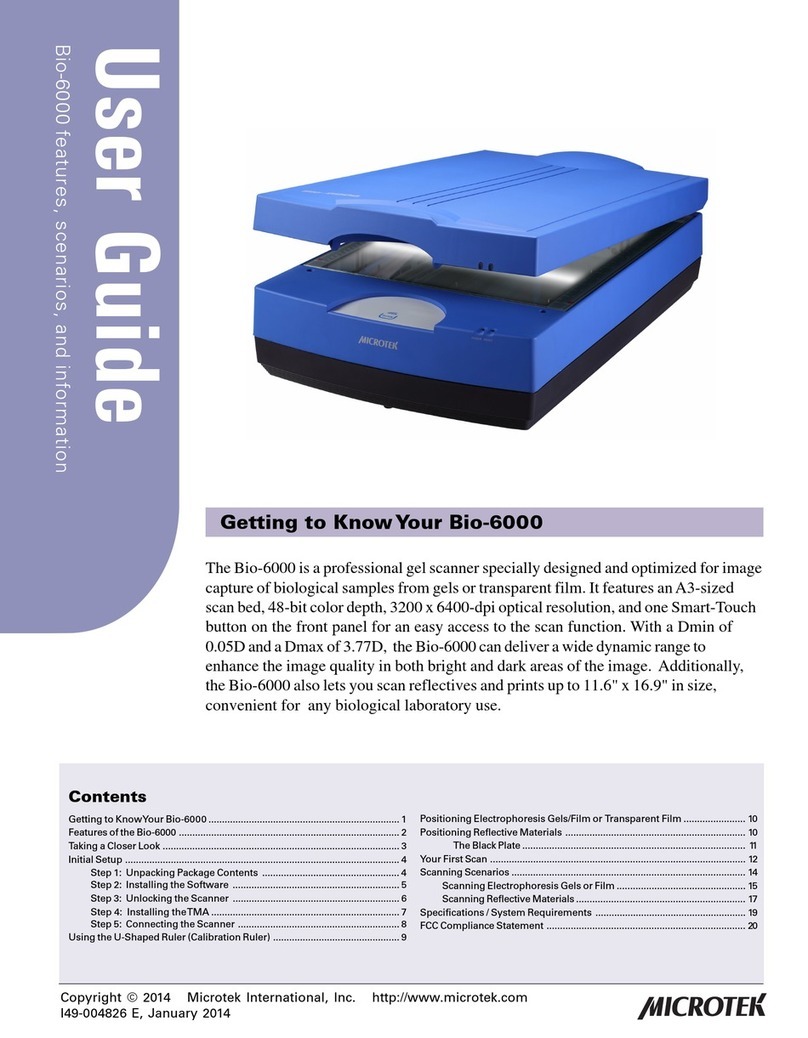
Microtek
Microtek Bio-6000 user guide
