manuals.online logo
Brands
  1. Home
  2. •
  3. Brands
  4. •
  5. Inovance
  6. •
  7. Controllers
  8. •
  9. Inovance H0U Series User manual

Inovance H0U Series User manual

1
H0U Series PLC User Manual
Thank you for purchasing the H0U series programmable logic controller (PLC) independently developed by
Inovance Control Technology Co., Ltd. Read the manual carefully to be familiar with the product features
and be able to use the product safely.
This manual describes the specication, features and usage of the H0U series PLC. For the developing
environment and design method of user programs, see the H0U Series PLC Programming Manual and the
H1U/H2U Series PLC Instruction & Programming Manual issued by Inovance.
The H0U series PLC has the following features:
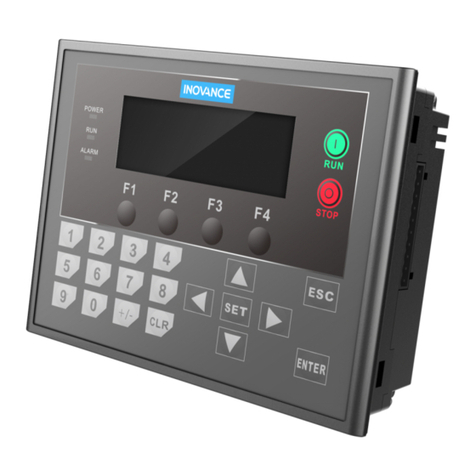
◆It integrates PLC and TOD programs and allows programming of control logics & display interface.
◆It supports all the instructions of the H1U and the CAN communication protocol.
◆It reaches the user memory space of 8k steps and the maximum capacity of the user TOD programs of
56 KB.
◆It has two independent communication ports (COM1, COM2), making it act as master or slave.
◆It supports 6-channel high-speed inputs and 2-channel high-speed outputs (only transistor output).
◆It supports display in both simplied Chinese and English, and switchover between the two languages
online.
◆It has a total of 25 functional keys, whose functions can be dened freely.
◆It allows you to download the PLC and TOD programs via AutoShop and HTodEditor.
Safety Information and Precautions
DANGER
◆Provide a safety circuit outside the PLC in the application so that the control system can still work safely
even if external power failure or PLC fault occurs. Take the following aspects into considerations in the
design:
◆In the external circuit of the PLC, an emergency stop circuit, a protection circuit, an interlock circuit
of forward/reverse rotation operation, and position upper/lower limit interlock circuit are necessary to
prevent equipment damage
◆To ensure safe running of the equipment, external protection circuit and safety mechanism must be
designed for the output signals that may cause serious accidents.
◆When the CPU of the PLC detects an abnormality of its own system, all outputs may be cut off. When
a failure occurs on the controller circuit, related outputs may be out of control. Thus, an appropriate
external circuit must be designed to ensure normal running of the equipment.
◆When the output units such as relay or transistor are damaged, related outputs will be out of control
and be continuously kept ON or OFF. Return the AC drive with damaged output unit to Inovance for
repair.
◆The PLC is designed for indoor electric environment. A lightning protection device must be installed for
the power supply system, so that lightening overvoltage is not applied on terminals of the PLC, avoiding
damage to the equipment.
■During Installation
WARNING
◆Install the PLC in places free from dust, oil smoke, conducting dust, corrosive gas, combustible gas,
high temperature, condensation, wind & rain, vibration and shock. In addition, electric shock, fire,
malfunction may also cause damage and deterioration to the equipment.
◆During screw hole processing and wiring, ensure that no metal filing and cable end falls into the
ventilation hole of the controller, because such stuff may causes a re, fault, or malfunction.
◆After installation of the newly purchased PLC is complete, ensure that there is no foreign stuff on the
surface of ventilation. Failure to comply may result in poor cooling effect during running, which may
lead to a re, fault or malfunction.
◆The installation and wiring must be secure and reliable. Poor contact may cause malfunction.
■In Design
2
■At Wiring
DANGER
◆Ensure that all power supplies are cut off before installation or wiring.
◆During screw hole processing and wiring, ensure that no metal lings or cable end drops into ventilation
holes of the controller. Failure to comply may result in a re, fault or malfunction.
◆Perform wiring or plug/remove the cable connector only after power-off. Failure to comply may result in
electric shock or damage to the circuit.
WARNING
◆Don’t provide external power supply to terminal 24+ of the main unit or expansion unit.
◆Use shielded cables for high-frequency signal input/output in applications with severe interference to
enhance anti-interference capacity of the system.
■During Running and Maintenance
DANGER
◆Connection or removal of the communication cable, cables of the extension card and cables of the
control unit can be performed only after power-off. Failure to comply may result in damage to the
equipment or malfunction.
◆The operations such as online modication, forcible output, RUN and STOP can be performed only
after you read the manual and guarantee safety.
WARNING
◆Treat scrapped PLC as ordinary industrial waste.
Product Information
■Designation Rules
H0U-0808 MRT -XP
3 4 5 6 7 821 9
-6AT
10
1: Product information H: Inovance controller
2: Series No. 0U: TOD+PLC integrated controller
3: Input points 08: 8 inputs
4: Output points 08: 8outputs
5: Module classication M: Main module of general-purpose controller
6: Output type R: Relay, T: Transistor
7: Output type Mixed output
8: Reserved for future expansion
9: CPU type XP: NXP-type CPU
10: Special function 6AT (standard): built-in analog extension card;
6ATC (customized): built-in analog extension card and CAN card; CAN (customized): built-in CAN card
■Basic Parameters
The following table describes the basic parameters of the H0U series PLC.
PLC Model Total
I/Os
I/O Features Communication
interface
Built-in
Analog
Card
Total
Inputs
High-Speed
Inputs
Total
Outputs
High-Speed
Outputs
Output
Type
H0U-0808MR-XP
16 8 2 x 60 kHz
4 x 10 kHz 8
- Relay
2 x RS485
1 x USB -
H0U-0808MRT-XP 2 x 100 kHz Transistor
H0U-1616MR-XP 32 16 2 x 60 kHz
4 x 10 kHz 16 - Relay
H0U-1616MRT-XP 2 x 100 kHz Transistor
H0U-0808MR-XP-
6AT 16 8 2 x 60 kHz
4 x 10 kHz 8
- Relay
2 x RS485
1 x USB 6AT
H0U-0808MRT-XP-
6AT 2 x 100 kHz Transistor
H0U-1616MR-XP-
6AT
32 16 2 x 60 kHz
4 x 10 kHz 16
- Relay
H0U-1616MRT-XP-
6AT 2 x 100 kHz Transistor
Note
Total frequencies of high-speed inputs do not exceed 70 kHz.
The following table describes the functions of the built-in extension cards.
Extension
Card
Model
Analog Input Analog Output Temperature Detection CAN
Communication
6AT
Voltage: -10 to +10 V
Current: 4–20 mA
Current: -20 to +20 mA
They are switched over
via soft component.
Voltage: -10 to +10 V
Current: 4–20 mA
Current: 0–20 mA
They are switched
over via soft
component.
A total of three terminals
are available, supporting
2-channel temperature
detection and also PT100
and TC detection, which are
switched over via software.
-
6ATC
Voltage: -10 to +10 V
Current: 4–20 mA
Current: -20 to +20 mA
They are switched over
via soft component.
Voltage: -10 to +10 V
Current: 4–20 mA
Current: 0–20 mA
They are switched
over via soft
component.
A total of three terminals
are available, supporting
2-channel temperature
detection and also PT100
and TC detection, which are
switched over via software.
One CAN
communication port
supporting CANlink
protocol
CAN - - -
One CAN
communication port
supporting CANlink
protocol
■General Specications
The following table describes the general specications of the H0U series PLC.
Environment Parameters
Use Condition Transportation
Condition
Storage
Condition
Type Parameter Unit
Climate condition
Ambient
temperature
Low temperature °C -5 -40 -40
High temperature °C 55 70 70
Humidity Relative humidity % 95
(30°C ± 2°C)
95
(40°C ± 2°C) -
Air pressure Low pressure kPa 70 70 70
High pressure kPa 106 106 106
Mechanical stress
Sine
vibration
Shift mm 3.5 (5–9 Hz) - -
Acceleration m/s2 10 (9–150 Hz) - -
Random
vibration
Acceleration
spectral density
m2/s3
(dB/Oct) -5–20 Hz: 1.92 dB
20–200 Hz: -3 dB -
Frequency range Hz - 5–200 -
Vibration direction - - X/Y/Z -
Shock Type - - Half-sine -
Acceleration m/s2 - 180 -
Dip Dip height m - 1 -
The following gure shows the installation dimensions of the H0U series PLC.
200 mm
146 mm
42 mm
Fixed
bolt hole
Front view Side view
3
Mechanical Design
Cut-out dimensions
(191 + 1) x (131 + 1) 138
192
Rear view
137
191
VESA mounting holes
4-M4
75.0
37.5
Unit: mm
The following gure shows the structure of the H0U series PLC.
Mounting
holes
J7
J2 J3 J4 J5 J6
J8
J9
Indicators
User-defined keys
Common keys
Display
J1
Common keys
The following table describes the structure of the H0U series PLC.
Terminal Terminal Name Terminal Terminal Name
J1 Output terminals (Y0 to Y7) J2 Power supply interface
J3 Serial communication port (RS485) J4 Input terminals (X0 to X7)
J5 Input terminals (X10 to X17) J6 USB client (Type B)
J7 Used for extended CAN function J8 Interface for built-in analog
extension card
J9 Output terminals (Y10 to Y17)
■Hardware Wiring
The following gure shows the wiring of the H0U series PLC.
H0U-1616MR Wiring
485+
485-
485+
485-
Y2
Y1
Y0
COM0
Y5
Y4
COM1
Y3
Y7
Y6
Y12
Y11
Y10
COM2
Y15
Y14
COM3
Y13
Y17
Y16
485+
485-
24V+
24V-
X0
X1
X2
X3
X4
X5
X10
X11
X12
X13
X14
X15
X16
X17
X6
X7
24V
GND
PE
COM1 COM2 COM0
1 18
V+
I+
VI-
V+
I+
VI-
IN1 IN2 CH1 CH2
L+
(L+) L-
(L-) I-
L+
(L+) L-
(L-) I-
OUT1 OUT2
V+
I+
VI-
V+
I+
VI-
8
ON
+24V CANH GND CANL 0V
1 2 3 4 5 6 7
■Communication Ports
The H0U series PLC has four communication ports as standard configuration. COM0, COM1 and
COM2 are standard RS485 communication interfaces. COM0 is used for user program downloading,
commissioning and monitoring. COM1 and COM2 are free interfaces and support the Modbus protocol, N:N
protocol, parallel protocol, HMI protocol, PC link protocol, RS instruction and Modbus instruction. The other
one is USB interface, which has the same function as COM0.
■Power Supply Specication
The H0U series PLC adopts the DC/DC power supply.
The input voltage of the DC/DC power supply is 24 V. The outputs are +5V/+24VDD/GND and +5V/COM
respectively. +5V/+24VDD/GND provides power supply to the digital circuits and relays of the H0U, while
+5V/COM provides power supply to transistor in the mixed output.
The DC/DC power supply adopts self-excitation to generate pulse width modulation (PWM) square wave
and uses TL431 for feedback. The power supply voltage of the main circuit is +5V/GND.
The following table describes the power supply specication of the H0U series PLC
Item Voltage (V) Current
(mA) Power (W)
Input 19.2–28.8 - -
Output
+5V 4.5–5.5 800 400
+24VDD 18.5–26.5 150 3.6
+5V 4.5–5.5 100 0.50
Total output power 8.1
■Input Specication
For the X terminals, the rated input voltage is 24 VDC. Relative to COM (0V), the X terminals is OFF when
the input voltage is below 4.0 V, is ON when the input voltage is above 15.0 V and is not xed when the
input voltage is 4.0–15.0 V. On the condition of rated input voltage of 24 VDC, the input current is 4–6 mA.
Item High-speed Inputs
X0 to X5 General Inputs
Signal input mode Sink input
Electrical
parameters
Input voltage 24 VDC
Input
impedance 3.3 kΩ 4.3 kΩ
Input ON Input current > 4.5 mA Input current > 4.5 mA
Input OFF Input current < 1.5 mA Input current < 1.5 mA
Filter function Hardware lter The other I/O terminals except X0 to X7are hardware lter. The
lter time is about 10 ms.
High-speed function
The maximum frequency counted at X0 and X1 reaches up to 60
kHz. The maximum frequency counted at X2 to X5 reaches up to
10 kHz. The total frequency is not higher than 60 kHz.
■Output Specication
For the Y terminals, the output mode is dry-contact. The output is active (state “1”) when the terminal is ON
and is inactive (state "0") when the terminal is OFF.
The 250 VAC reinforced insulation must be satisfied between the relay outputs and the logic circuit of
the PLC. In addition, the 250 VAC reinforced insulation must be satised between the output terminals of
different common terminals.
Item Relay Output Transistor Output
Circuit voltage 250 VAC, 30 VDC below 5–24 VDC
Circuit insulation Relay mechanical insulation Optically coupling insulation
Action indication Output contact closing Contact closing when optically
coupling is driven
Leakage current at open circuit - < 0.1 mA/30 VDC
Minimum load 2 mA/5 VDC 5 mA (5–24 VDC)
Maximum
output
current
Resistive load
2 A for a point
8 A for 4 points in a group sharing
a common terminal
8 A for 8 points in a group sharing
a common terminal
0.5 A for a point
0.8 A for 4 points
1.6 A for 8 points
Inductive load 220 VAC, 80 VA High-speed outputs: 7.2 W/24 VDC
Others: 12 W/24 VDC
ON response time 20 ms (max.) High-speed outputs: 10 us
Others: 0.5 ms
OFF response time 20 ms (max.)
High-speed output frequency - 100 kHz per channel (max.)
Output common terminal Each group shares a common terminal COM. The groups are insulated.
Fuse protection -
Note
When some or all transistors in each group are with load, the average current for each channel must not exceed
0.2 A. The maximum current for a single channel must not exceed 0.5 A.
■Internal Equivalent Circuit
The following gure shows the internal equivalent circuit of relay output. Output terminals are divided into
several groups, with each group electrically isolated. The output contacts of different groups are connected
to different power circuits.
H0U-1616MR-XP internal
equivalent circuit
24 VDC power
supply
Power supply of the
internal logic circuit
Logic processing
circuit
Output drive circuit
Output group 0
Output group 3
COM0
Y0
Y1
Y2
Y3
COM3
Y14
Y15
Y16
Y17
The following gure shows the internal equivalent circuit of mixed output of transistor and relay. Output
terminals are divided into several groups, with each group electrically isolated. The output contacts of
different groups are connected to different power circuits. Transistor output can be applied only to 24 VDC
load circuit.
H0U-1616MRT-XP
internal equivalent circuit
Power supply of the
internal logic circuit
5 VDC power
supply
Logic processing
circuit
Output drive circuit
24 VDC
power supply
Output group 0:
transistor output
Output group 1-3:
relay output
COM0
Y0
Y1
Y2
Y3
COM3
Y14
Y15
Y16
Y17
Electrical Design
456
The following gure shows the internal equivalent circuit of PLC signal input. The user circuit is connected
to the internal PLC circuit via wiring terminals. Sink input wiring is always used for H0U.
User signal wiring
All signal input devices
24 VDC auxiliary
power supply
Logic
processing
circuit
Internal equivalent circuit of
PLC main module
24V
0V
24V+
24V-
X0
X1
X2
Xn
For the inductive load connected to the AC circuit, use the RC instantaneous voltage snubber circuit for the
external circuit. For the inductive load connected to the DC circuit, add a ywheel diode, as shown in the
following gure.
24V+
24V+
AC-L
Y1
Y10
Y3
24V-
24V-
AC-N
1N40 04
Inductive load
Inductive load
Inductive load
1N40 04
R C
R = 200 Ω, 2 W
C = 0.022 uF, 250 VAC
Freewheel diode
Freewheel diode
■Basic Specications of the Integrated Equipment
1. Text specications
Item Specications
Display
property
Display area 192 x 64
LCD type Yellow green background, dark blue character
Background light Yellow green LED background light
Language English/Chinese
Physical
dimensions 130 x 65 mm
Display size 104 x 39 mm
Weight 105 g
Power supply 3.3 V
Storage Flash 56 KB
2. PLC specications
Item Specications
Program execution mode Cycling scanning
Programming mode Ladder logic diagram, instruction list, SFC
Processing speed 0.26 ns (basic instruction)
Retentive at power failure Flashrom retentive
User program capacity 8 k steps
I/O points 8 inputs 8 outputs, 16 inputs 16 outputs
High-speed processing
capability 2-channel high-speed counting, 2 pulse output
Communication function RS485/USB communication
■Description of Keys on the Operation Panel
1. Key setting
The operation panel consists of 25 keys. The functions of the keys are the same as those of the HMI.
2. Functions of the keys
Key Name Function Description
ESC
On the default interface, press this key to enter the main menu.
When an alarm occurs, press this key to returns to the interface before
occurrence of the alarm.
In the menu mode or parameter edit mode, press this key to return to the
previous operation or give up the current operation.
SET
When an editable register parameter exists and allows edition, press this key to
enter the editing mode.
In the parameter editing mode, press this key to give up editing of this parameter
and go to the next parameter. If there is no next parameter to be edited, the
editing mode will be exited.
If there is no editable parameter or the parameters do not allow edition, pressing
this key is invalid.
Down
In the menu control, if there is a cursor line, press this key to move the cursor
down to the next cursor line. If a parameter is being set, press this key to
increase the value where the cursor is located by 1.
Up
In the menu control, if there is a cursor line, press this key to move the cursor
up to the previous cursor line. If a parameter is being set, press this key to
decrease the value where the cursor is located by 1.
Left If there is a cursor during parameter or item setting, press this key to move the
cursor left.
Right If there is a cursor during parameter or item setting, press this key to move the
cursor right.
Conrm
In the menu mode with a cursor line, press this key to go to the next-level menu
or view parameter information of the selected item.
In the parameter editing state, press this key to conrm edition of the parameter
and enter the editing state of the next parameter.
Numbers
0–9 Press these keys to enter the corresponding number when setting parameters.
+/- Press this key to set the positive or negative value of the data.
CLR Press this key to clear the setting.
Note
Besides the default functions, basic function keys can also be used as user-dened keys, and you can dene their
functions by using the background software.
3. User-dened keys
Another six user-defined keys are available, including F1 to F4, RUN, and STOP. You can define the
functions of these keys by using the background software. The functions include coil setting, page skip, and
register setting.
4. Indicators
The H0U has four indicators, as described in the following table.
Indicator State Description
POWER OFF There is no power supply.
Steady ON The system is powered on.
RUN OFF The H0U is partially stopped.
Steady ON The H0U is partially running.
ALARM OFF The system is in normal state without fault,
or the faults have been rectied.
Steady ON The system is faulty with alarm.
Standby indicator N/A N/A
■H0U Soft Component
The use of soft components of the H0U series PLC is the same as that of the H1U series PLC.
■PLC Instruction List
The basic PLC instructions of H0U are the same as those of H1U.
Warranty Agreement
1. The warranty period of the product is 2 years (refer to the barcode on the equipment). During the
warranty period, if the product fails or is damaged under the condition of normal use by following the
instructions, Inovance will be responsible for free maintenance.
2. Within the warranty period, maintenance will be charged for the damages caused by the following
reasons:
a. Improper use or repair/modication without prior permission
b. Fire, ood, abnormal voltage, other disasters and secondary disaster
c. Hardware damage caused by dropping or transportation after procurement
d. Improper operation
e. Trouble out of the equipment (for example, external device)
3. If there is any failure or damage to the product, please correctly ll out the Product Warranty Card in
detail.
4. The maintenance fee is charged according to the latest Maintenance Price List of Inovance.
5. The Product Warranty Card is not re-issued. Please keep the card and present it to the maintenance
personnel when asking for maintenance.
6. If there is any problem during the service, contact Inovance’s agent or Inovance directly.
7. This agreement shall be interpreted by Shenzhen Inovance Technology Co., Ltd.
Product Warranty Card
Customer
information
Add. of unit:
Name of unit:
P.C.:
Contact person:
Tel.:
Product
information
Product model:
Body barcode (Attach here):
Name of agent:
Failure
information
(Maintenance time and content):
Maintenance personnel:
Service Department, Shenzhen Inovance Technology Co., Ltd.
Address: Block E, Hongwei Industry Park, Liuxian Road, Baocheng No. 70 Zone, Bao’an
District, Shenzhen P.C.: 518101
Website: www.inovance.cn
Programming Reference
789

Other manuals for H0U Series

2

This manual suits for next models

11

Other Inovance Controllers manuals

Inovance Monarch NICE300new Series User manual

Inovance

Inovance Monarch NICE300new Series User manual

Inovance H0U-88B1G Troubleshooting guide

Inovance

Inovance H0U-88B1G Troubleshooting guide

Inovance H1U-0806MT User manual

Inovance

Inovance H1U-0806MT User manual

Inovance Easy501 User manual

Inovance

Inovance Easy501 User manual

Inovance MD500 Series User manual

Inovance

Inovance MD500 Series User manual

Inovance Easy320 User manual

Inovance

Inovance Easy320 User manual

Inovance Easy 301 User manual

Inovance

Inovance Easy 301 User manual

Inovance MD500 Series User manual

Inovance

Inovance MD500 Series User manual

Inovance AC800 Series User manual

Inovance

Inovance AC800 Series User manual

Inovance AM403 Series User manual

Inovance

Inovance AM403 Series User manual

Inovance inovance User manual

Inovance

Inovance inovance User manual

Inovance H0U Series User manual

Inovance

Inovance H0U Series User manual

Inovance H3U Series User manual

Inovance

Inovance H3U Series User manual

Inovance CAN200 Series User manual

Inovance

Inovance CAN200 Series User manual

Inovance Easy521 User manual

Inovance

Inovance Easy521 User manual

Inovance AM600 Series User manual

Inovance

Inovance AM600 Series User manual

Inovance H5U Series User manual

Inovance

Inovance H5U Series User manual

Inovance IS620P Series User manual

Inovance

Inovance IS620P Series User manual

Inovance MD310 Series User manual

Inovance

Inovance MD310 Series User manual

Inovance NICE1000 User guide

Inovance

Inovance NICE1000 User guide

Inovance H3U Series User manual

Inovance

Inovance H3U Series User manual

Inovance H3U Series Owner's manual

Inovance

Inovance H3U Series Owner's manual

Inovance AC700 Series User manual

Inovance

Inovance AC700 Series User manual

Popular Controllers manuals by other brands

Actreg ADA SERIES Assembly & Maintenance Instructions

Actreg

Actreg ADA SERIES Assembly & Maintenance Instructions

Johnson Controls VMA1200 Series Mounting and wiring instruction

Johnson Controls

Johnson Controls VMA1200 Series Mounting and wiring instruction

Wulfsberg C-5000 installation manual

Wulfsberg

Wulfsberg C-5000 installation manual

ThermoPro NP17-12 Pro MANAUL FOR SAFITY AND USE

ThermoPro

ThermoPro NP17-12 Pro MANAUL FOR SAFITY AND USE

Texas Instruments DRV8833 manual

Texas Instruments

Texas Instruments DRV8833 manual

ABB Relion 620 Series installation manual

ABB

ABB Relion 620 Series installation manual

Vertiv Liebert EXL 31 Installer/user guide

Vertiv

Vertiv Liebert EXL 31 Installer/user guide

EFI E-85 Installation and service guide

EFI

EFI E-85 Installation and service guide

SEA USER 1 - 24v DG R1 manual

SEA

SEA USER 1 - 24v DG R1 manual

Messana mZone installation guide

Messana

Messana mZone installation guide

Daikin RoCon+ HP Series operating instructions

Daikin

Daikin RoCon+ HP Series operating instructions

Megadodo Simulation Games DecaMove manual

Megadodo Simulation Games

Megadodo Simulation Games DecaMove manual

YASKAWA MP2300Siec Hardware manual

YASKAWA

YASKAWA MP2300Siec Hardware manual

Eurotronic CZW-250 operating instructions

Eurotronic

Eurotronic CZW-250 operating instructions

LOVATO ELECTRIC RGK600 instruction manual

LOVATO ELECTRIC

LOVATO ELECTRIC RGK600 instruction manual

haso HA1005 Installation and use instruction

haso

haso HA1005 Installation and use instruction

Oceanic Systems NMEA2000 5971 Installation and operation manual

Oceanic Systems

Oceanic Systems NMEA2000 5971 Installation and operation manual

Emerson Asset Management Tag Installation, operation and maintenance manual

Emerson

Emerson Asset Management Tag Installation, operation and maintenance manual

manuals.online logo
manuals.online logoBrands
  • About & Mission
  • Contact us
  • Privacy Policy
  • Terms and Conditions

Copyright 2025 Manuals.Online. All Rights Reserved.