INRODA PUMA User manual
PUMA
SUBSOILER
INSTRUCTIONS MANUAL
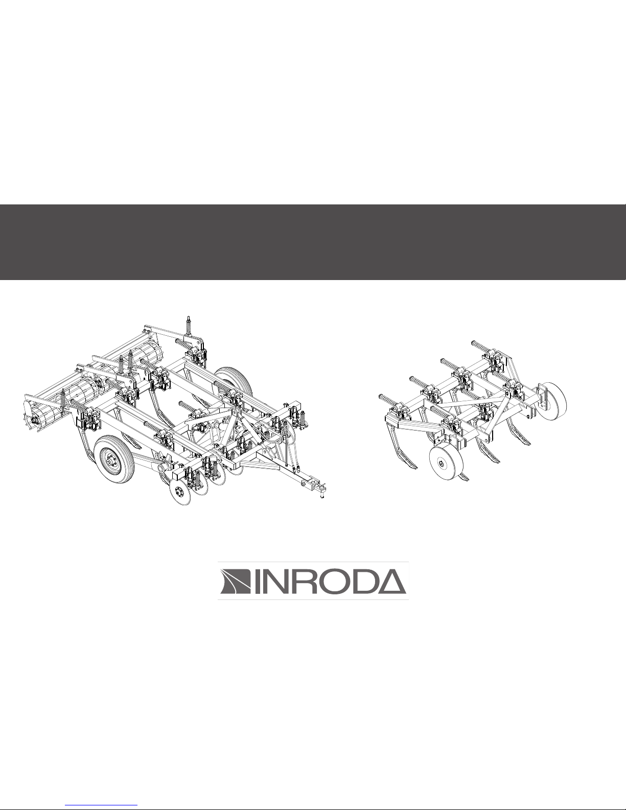
PUMA H

01
01 - Introduction
- Warranty certifi cate
02 - Parts:
- Subsoiler Puma
- Subsoiler Puma H
03 - Safety Rules
- Transport over truck
04 - Technical features:
05 - Assembly
- Assembly of ground wheel on the frame
- Wheel Assembly
- Rear roller Assembly
- Coulter Blade assembly
- Hydraulic system assembly
- Drawbar assembly
- Shanks assembly
06 - Hitch:
- Hitching the Subsoiler in the tractor
- Puma H Hitch Procedure
- Puma H Alignment Procedure
- Puma H Leveling Procedure
07 - Adjustment and operations:
- Depth Adjustment for Subsoiler Puma
- Depth Adjustment for Subsoiler Puma H
- Pressure Adjustment in auto-return Device
- Spacing between shanks Puma H
- Coulter Blade adjustment
- Rear Roller Subsoiler Puma
- Operations
08 - Maintenance:
- Lubrication
- Operations maintenance - Problems During the Subsoilers Works
- Operations maintenance - Problems With Hydráulics System
- Lubrication point
- Tyres infl ations
- Subsoiler transport
10 - Clear procedure
11 - Spare parts
12 - Identifi cation
TABLE OF CONTENT
2
3
4
5
6 - 7
8
9
10
10
10
11
11
12
12
13 - 14
15
15
16
16
17
17
18
18
19
19
20
21
21
22
23
24
25
25
26
26
26

02
INTRODUCTION
This manual is an important part of your machine provided by INRODA
Indústria de Roçadeiras Desbravador Avaré Ltda and should remain with
the machine when you sell it.
Reading your operator’s manual will help you and others avoid personal
injury or damage to the machine. Information given in this manual will pro-
vide the operator with the safest and most effective use of the machine.
Knowing how to operate this machine safely and correctly will allow you to
train others who may operate this machine.
The dealer will delivery the equipments and explain about safe working,
maintenance technical support and provide further details about the terms
and conditions of the warranty.
To obtain performance of the warranty, the original purchaser must re-
quest warranty service from a distributor authorized to sell the product to
be serviced .
Following the instructions of this manual and correct maintenance it will
provide a long years of trouble-free from your implement.

03
WARRANTY CERTIFICATE
INRODA Indústria de Roçadeiras Desbravador Avaré Ltda., as manufacturer warrants all parts, (except those referred to below), of the product
described in this manual to be free from defects in materials and workmanship during the period of 6 (six) month from the invoice date to the first
purchaser following the rules bellow :
WARRANTY COVER
The warranty will cover defective parts not subject to normal wear and tear will be repaired or replaced at our option during the warranty period
when the use follow the content of this manual.
To requesting the warranty is necessary show the warranty certificate and invoice with all fields filled in observance of the warranty rules.
WARRANTY VOID CONDITIONS
This warranty does not apply to equipment or parts that have been subjected to improper or unauthorized installation or alteration and modifica-
tion, misuse, negligence, accident, overloading, overspeeding, improper maintenance, repair or storage so as, in our judgment, to adversely affect its
performance and reliability;
Failure to follow recommended operating and maintenance procedures, including maintenance in dealer unauthorized by the manufacturer, also
voids warranty
Maintenance and replacement of parts by not genuine INRODA parts;
Project changes also void the warranty;
Incomplete or incorrect filling of the warranty certificate.
THE WARRANTY DOES NOT COVER:
Damages caused by accidents;
Part damaged by the normal wear unless problems from defects in materials and workmanship.
Fluids and lubricate oil;
Transportation charges on product submitted for repair or replacement under this warranty must be borne by purchaser.
GENERAL CONDITIONS
All equipment and parts replaced under this warranty will become the property of the manufacturer, INRODA;
The warranty of parts replaced are limited of the equipment warranty period above described.
Delay in warranty services does not provide right to reimbursement, indemnification or extending the warranty
04
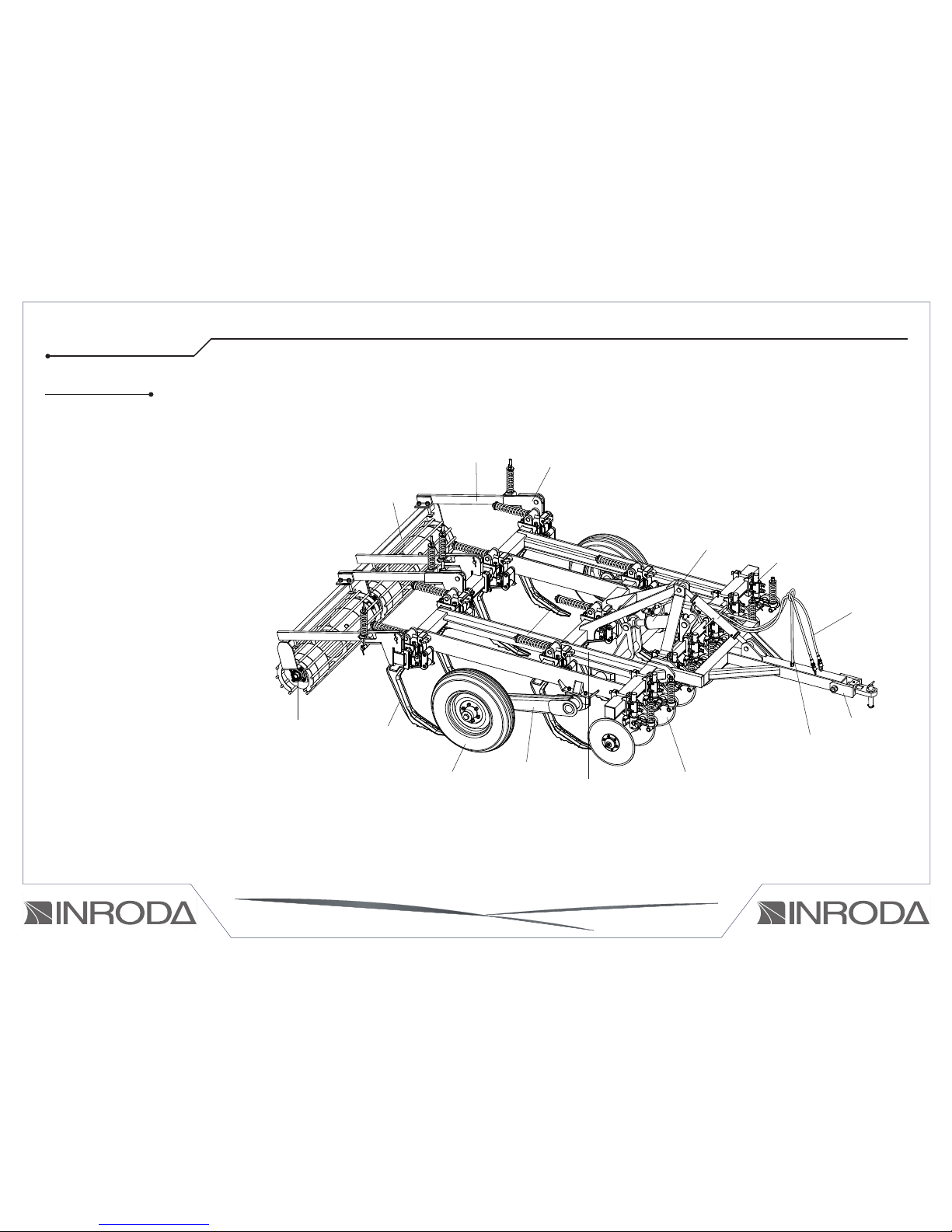
01 - Complete auto-return shank
02 - Complete Wheel
03 - Complete wheel articulation support
04 - Frame
05 - Hydraulic hose support
06 - Hydraulic hoses
07 - Rear roller bearing
08 - Drawbar adjuster
09 - Drawbar hitch device
10 - Rear roller
11 - Complete coulter blade
12 - Attachment rear roller support
13 - Hydraulic cylinder
14 - Rear roller oscillation bar
02 - PARTS
13
14
07
05
12
08
DRAWING 01
09
06
09
04
14
01
02 03 11
10
SUBSOILER PUMA
This manual suits for next models
1
Table of contents
Other INRODA Farm Equipment manuals

Popular Farm Equipment manuals by other brands

Schaffert
Schaffert Rebounder Mounting instructions

Stocks AG
Stocks AG Fan Jet Pro Plus 65 Original Operating Manual and parts list

Cumberland
Cumberland Integra Feed-Link Installation and operation manual

BROWN
BROWN BDHP-1250 Owner's/operator's manual

Molon
Molon BCS operating instructions

Vaderstad
Vaderstad Rapid Series instructions


