Inscape Data LinkPower PIS6095 User manual

Updated 08/01/2019
LinkPower PIS6095
2.5Mbps 2-Port Gigabit 802.3bt High-
Power PoE Injector
USER MANUAL
Inscape Data Corporation
2012 Hartog Drive
San Jose, CA 95131
U.S.A.
© Copyright 2023, Inscape Data Corporation, All Rights Reserved. LinkPower and Inscape Data
are trademarks of Inscape Data Corporation
Disclaimer: While every effort is made to ensure the information given is accurate, Inscape Data
Corporation does not accept liability for any errors or mistakes which may arise. All information and
specifications are subject to change without notice.

LinkPower PIS6095 Outdoor 30W Gigabit PoE Injector
Page 2 of 19
Certification
Inscape Data Corporation certifies that this product met its published specifications at time of
shipment from the factory.
FCC Statement
This equipment has been tested and found to comply with the limits for a Class A digital
device, pursuant to Part 15 of the FCC Rules. These limits are designed to provide
reasonable protection against harmful interference when the equipment is operated in a
commercial environment. This equipment generates, uses, and can radiate radio frequency
energy and, if not installed and used in accordance with the instruction manual, may cause
harmful interference to radio communications. Operation of this equipment in a residential
area is likely to cause harmful interference in which case the user will be required to correct
the interference at his own expense.
The user is cautioned that changes and modifications made to the equipment without approval
of the manufacturer could void the user's authority to operate this equipment.
The manufacturer is not responsible for any radio or TV interference caused by unauthorized
modifications to this equipment. Such modifications could void the user’s authority to operate
the equipment.
Industry Canada Statement
This Class A digital apparatus complies with Canadian ICES-003.
CE Statement
This product complies with the European Low Voltage Directive 73/23/EEC and EMC Directive
89/336/EEC as amended by European Directive 93/68/EEC.
Warning: This is a class A product. In a domestic environment this product may cause radio
interference in which case the user may be required to take adequate measures.
UL Recognized Statement
The power supply of this product has been investigated using applicable construction and
performance requirements by UL, and when installed in accordance with the manufacturer’s
installation instructions, should provide a safe, code-compliant installation.

LinkPower PIS6095 Outdoor 30W Gigabit PoE Injector
Page 3 of 19
Safety Summary
The following general safety precautions must be observed during all phases of operation of
this instrument. Failure to comply with these precautions or with specific warnings elsewhere
in this manual violates safety standards of design, manufacture, and intended use of the
instrument. Inscape Data Corporation assumes no liability for the customer’s failure to
comply with these requirements.
Before Applying Power
Verify that the product is set to match the available line voltage and all safety precautions are
taken.
Over Temperature Warning
To prevent the switch from overheating, do not operate it in an area that exceeds the
maximum recommended ambient temperature of (75°C). To prevent product cooling
restriction, allow at least 3 inches (7.6 cm) of clearance around the product after installation.
Ground the Instrument
To minimize shock hazard, the instrument chassis and cabinet must be connected to an
electrical ground. The instrument must be connected to the ac power supply mains through a
three-conductor power cable, with the third wire firmly connected to an electrical ground
(safety ground) at the power outlet. For instruments designed to be hard-wired to the ac power
lines (supply mains), connect the protective earth terminal to a protective conductor before
any other connection is made. Any interruption of the protective (grounding) conductor or
disconnection of the protective earth terminal will cause a potential shock hazard that could
result in personal injury.
When installing the unit, always make the ground connection first and disconnect it last.
Jewelry Removal Warning
Before working on equipment that is connected to power lines, remove jewelry (including
rings, necklaces, and watches). Metal objects will heat up when connected to power and
ground and can cause serious burns or weld the metal object to the terminals.
Do not Operate in Explosive Atmosphere
Do not operate the product in the presence of flammable gases or fumes.

LinkPower PIS6095 Outdoor 30W Gigabit PoE Injector
Page 4 of 19
Chassis Power Connection
Before connecting or disconnecting ground or power wires to the chassis, ensure that power
is removed from the device. To ensure that all power is OFF, locate the circuit breaker on the
panel board that services the device, switch the circuit breaker to the OFF position, and tape
the switch handle of the circuit breaker in the OFF position.
Work During Lightning Activity
Do not work on the system or connect or disconnect cables during periods of lightning activity.
Comply with Local and National Electrical Codes
Installation of the equipment must comply with local and national electrical codes
Do Not Exceed Input and Output Ratings
Do not operate the product to exceed the power input and output ratings.
This product Conforms to the following safety standards
Specification
Description
Regulatory Compliance
Products with the CE Marking are compliant with the
89/336/EEC and 73/23/EEC directives, which include the
safety and EMC standards listed.
Safety & EMC
CE mark, commercial, FCC Part 15 Class B, RoHS UL60950-
1, TUV EN60950-1 Approved
Packing List
Each package includes the following items:
•PIS2060 or PIS2095 (1)
•WECK0001 Waterproof Ethernet Connector Kit (2)
•WPCK0001-3 - AC Power Cable with one 3-PIN AC Power Connector (1)
•User Manual (1)
•Warranty Sheet (1)

LinkPower PIS6095 Outdoor 30W Gigabit PoE Injector
Page 5 of 19
TABLE OF CONTENTS
1INTRODUCTION ..........................................................................................................................................6
2PRODUCT OVERVIEW ...............................................................................................................................7
2.1 PIS6095 SYSTEM VIEW ............................................................................................................................7
2.2 CONNECTOR SYSTEM INTERFACE..............................................................................................................7
2.3 SYSTEM POWER INPUTS ............................................................................................................................8
2.4 EARTH GROUND........................................................................................................................................8
2.5 GROUNDING THE SWITCH BY USING WPCK0002 AC POWER CORD ........................................................8
2.6 PIS6095 INSTALLATION AND CONFIGURATION..........................................................................................9
2.6.1 PoE Power Rating and Forwarding Specification.............................................................................10
2.6.2 Before You Start .................................................................................................................................12
2.6.3 Installation Procedure .......................................................................................................................13
2.6.4 Hardware Installation........................................................................................................................14
2.6.5 Pole Mounting the PIS6095 Outdoor PoE Injector ...........................................................................15
2.7 POE INJECTOR AND CABLE LENGTH CONSIDERATION.............................................................................15

LinkPower PIS6095 Outdoor 30W Gigabit PoE Injector
Page 6 of 19
1 Introduction
Inscape Data’s LinkPower™ PIS6095 2-port 10/100/1000/2500M PoE (Power over Ethernet)
Injector is a Gigabit high power high-power DC PoE injector, and it supports IEEE802.3bt
PoE++ standard and is backward compatible with IEEE 802.3af/IEEE802.3at standards. The
maximum output power is 90W for PIS6095. There are two RJ45 network ports, and one of
which is used as an uplink port to a switch or to another network device. Another network
port is the PoE port that integrated PoE power output and network data. The high power DC
output simplifies the overall installation by eliminating the need for a power cord, such as, high
power network dome cameras or other high power IP devices.

LinkPower PIS6095 Outdoor 30W Gigabit PoE Injector
Page 7 of 19
2 Product Overview
2.1 PIS6095 System View
2.2 Connector System Interface
The PIS6095 system is housed in a 7.63x4.63x3.09 Inch IP67 weatherproof enclosure. The
Connector System Interface consists of two Waterproof RJ45 PoE Connectors, and an
Waterproof AC Connector. Each of the RJ45 PoE Connector and AC Connector has an LED
Indicator. The functions of the switch and LED status is summarized in a table and the picture
below.
PIS6095 Front Panel View

LinkPower PIS6095 Outdoor 30W Gigabit PoE Injector
Page 8 of 19
User Buttons and Ports
Item
No.
Function
Description
1
AC PWR & LED
100 ~ 240V AC Power Input Port
LED in ON (Green), when Power is connected
2
PoE Out Port & LED
PoE is Active, when LED is ON (Green)
2.3 System Power Inputs
The PIS6095 model accepts 100 ~ 240V AC power input. The industrial power termination
block provides secure and installation flexibility.
2.4 Earth Ground
The system provides the grounding by using the Ground Wire (see Section 2.6) to ground the
equipment for safety and protection of the system. It is highly recommended that you’re to
perform both grounding procedures for maximum safety and protection of your equipment.
However, at least of the grounding MUST be performed, otherwise any product damage
caused by improper or no grounding will not be covered under warranty.
2.5 Grounding the Switch by Using WPCK0002 AC Power Cord
If the installation site has no grounding strips or earth ground connection, then you must
ground the Injector through the AC wire of the power cord.
Please make sure that: Please make sure that:
1. There are two ways to ground the injector, namely grounding lug and power cord
grounding pin.
2. First, to use the grounding lug for grounding, please see the Figure 1-B
3. Next, the power cord has a ground pin, Aka, PE (Protective Earth) terminal, Figure 1-A.
4. The ground contact in the power outlet is securely connected to the ground in the power
distribution room or on the AC transformer side.
5. The power cord is securely connected to the power source.
6. If the ground contact in the power outlet is not connected to the ground, report and
resolve the problem and reconstruct the grounding system.
NOTE: PRODUCT DAMAGE CAUSED BY IMPROPER OR NO GROUNDING WILL NOT BE COVERED

LinkPower PIS6095 Outdoor 30W Gigabit PoE Injector
Page 9 of 19
UNDER WARRANTY!
Figure 1-A
Figure 1-B
WPCK0002 Waterproof Power Cord
NOTE: Grounding through the AC power cord’s Grounding Pin
2.6 PIS6095 Installation and Configuration
The PIS6095 Gigabit Outdoor PoE Injector supports most popular brands of IP physical
security and IT networking equipment.
LinkPower PIS6095 Outdoor 30W Gigabit PoE Injector
Page 10 of 19
To connect powered devices like PoE enabled IP video camera and wireless bridges to the
PIS6095, follow the power device manufacturer’s voltage and current recommendation.
Using the wrong voltage to power your device will render your device inoperable. The
PIS6095 System Includes Conduit Piping and Plain Cable weatherproof Connector Kit.
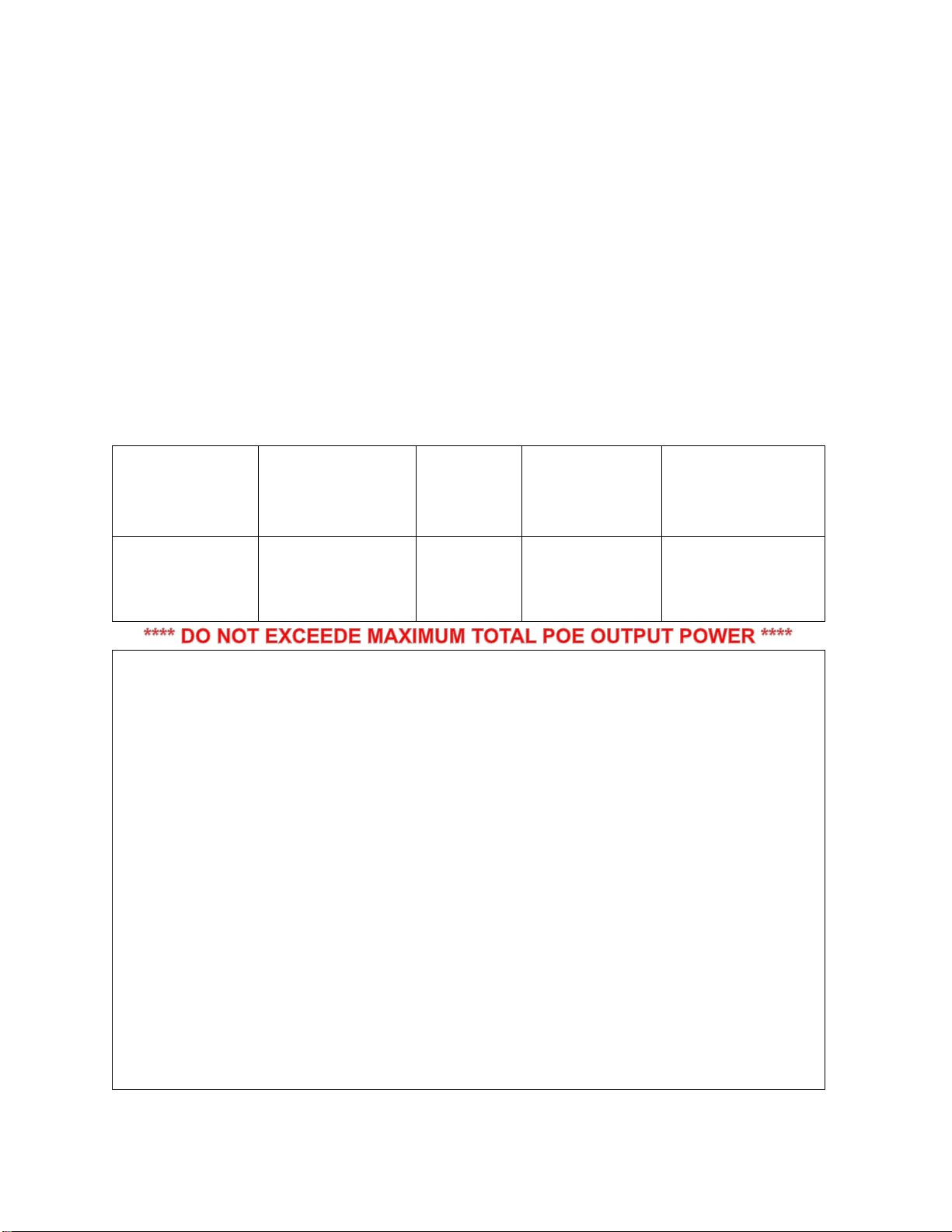
2.6.1 PoE Power Rating and Forwarding Specification
The PIS6095 90W Gigabit Outdoor PoE Injector is designed to support high power output, up
to 90 watts based on the IEEE802.3bt PoE++ high power standard, compatible with
IEEE802.3af/ IEEE802.3at standard . The following information reflects important PoE
power forwarding capabilities of the PIS6095.
Maximum Power Forwarding Specification per Port
Power Input
PoE/AC Port
Output Voltage
(DC)
Voltage
Tolerance
Max PoE/AC
Port Output
Current
Max PoE/AC Port
Output Power
(Watt)
AC PWR:
100~250V AC
50/60Hz
50.0
+/- 5%
1.8 Amp
90W
WARNING
•THE PIS6095 IS DESIGNED TO SUPPLY UP TO 30 WATTS OF TOTAL POWER AT THE
RATED 70ºC TEMPERATURE SPECIFICATION. OPERATING THE PIS6095 OUTSIDE
OF THE TOTAL POWER AND TEMPERATURE MAY HINDER THE POWER DEVICE
OPERATING AND/OR DAMAGE THE PIS6095 DEVICE.
•POWER OVER ETHERNET DEVICES NOT RATED TO BE POWERED OVER CAT5, 5E,
OR 6 CABLES SHALL NOT BE USED WITH THE PIS6095.
•PLEASE USE CAT5 OR HIGHER RATED CABLES TO ENSURE POWER RATED POWER
LEVELS ARE DELIVERED TO THE POWERED DEVICE.
•DO NOT EXCEED THE POWER FORWARDING CAPABILITY OF THE PIS6095. DOING
SO MAY RISK OPERATING THE PIS6095, POWERED DEVICE, AND POE CABLES AT
HAZARDOUS LEVEL. IT MAY ALSO CAUSE FIRE DANGER. INSCAPE DATA IS NOT
RESPONSIBLE FOR DAMAGES CAUSED TO THE POWERED DEVICE OR THE PIS6095
BY ABNORMAL USE OF THE PRODUCT.
•PLEASE FOLLOW THE TIA/EIA 568B TELECOMMUNICATION CABLING STANDARD

LinkPower PIS6095 Outdoor 30W Gigabit PoE Injector
Page 11 of 19
FOR RJ45 TERMINATION REFERENCE. INCORRECT TERMINATION WILL CAUSE
POWER DAMAGE TO THE PIS6095 AND/OR THE POWERED DEVICE.
LIMITED WARRANTY
IMPORTANT: PLEASE READ THIS LIMITED WARRANTY AND ENCLOSED LIMITED
WARRANTY AND END USER LICENSE AGREEMENT CAREFULLY. INSTALLING OR
USING INSCAPE DATA-SUPPLIED PRODUCT AND SOFTWARE CONSTITUTES
ACCEPTANCE OF THIS AGREEMENT.
IN NO EVENT SHALL INSCAPE DATA BE LIABLE TO YOU OR ANY OTHER PARTY FOR ANY
DIRECT, INDIRECT, GENERAL, SPECIAL, INCIDENTAL, CONSEQUENTIAL, EXEMPLARY
OR OTHER DAMAGE ARISING OUT OF THE USE OR INABILITY TO USE THE PRODUCT
(INCLUDING, WITHOUT LIMITATION, DAMAGES FOR LOSS OF BUSINESS PROFITS,
BUSINESS INTERRUPTION, LOSS OF BUSINESS INFORMATION OR ANY OTHER
PECUNIARY LOSS, OR FROM ANY BREACH OF WARRANTY, EVEN IF INSCAPE DATA HAS
BEEN ADVISED OF THE POSSIBILITY OF SUCH DAMAGES. (SOME STATES DO NOT
ALLOW THE EXCLUSION OR LIMITATION OF INCIDENTAL OR CONSEQUENTIAL
DAMAGES, SO THE ABOVE EXCLUSION OR LIMITATION MAY NOT APPLY TO YOU.) IN NO
CASE SHALL INSCAPE DATA’S LIABILITY EXCEED THE AMOUNT YOU PAID FOR THE
PRODUCT.

LinkPower PIS6095 Outdoor 30W Gigabit PoE Injector
Page 12 of 19
2.6.2 Before You Start
Review the package contents, system requirements, and application example before
proceeding with Section 2.7.3 Installation Procedure.
Package Contents
•Link Power PIS2060 or PIS2095 Outdoor High-Power Gigabit PoE Injector
•WECK0001 Waterproof Ethernet Connector Kit (2)
•WPCK0001-3 - AC Power Cable with one 3-PIN AC Power Connector (1)
•User Manual (1)
•WMK0002-S Wall Mounting Kit (Optional Accessory)
Required Accessories
Items
Specification
Notes
Ground Wire
14 AWG Copper
Wire (Minimum)
Attached to backside of the PIS6095
and appropriate common Earth Ground.
Product damage caused by improper
grounding is not covered under
warranty!
Torque Wrench
20kgf-cm or 1.44 lbf-
ft.
All nuts and bolts shall not be tightened
beyond specified torque setting
CAT5/5e/6 Cable
Termination
TIA-568B Standard
Improper termination will damage the
device and void your warranty
Recommended Accessories
Items
Specification
Notes
Shielded PoE Cable
Outdoor rated
Cat5/5e STP, FTP
The use of shielded twisted pair cable (1
to 100 meter) is recommended
Shielded RJ-45 Jack
Shielded
The use of shielded RJ-45 connectors
used for both ends is recommended
Weatherproof Sealing
Tape
Rubber Mastic or
equivalent
(i.e. Coax-Seal)
Sealing of electrical and PoE connector
at both end is recommended to ensure
installation and equipment longevity.

LinkPower PIS6095 Outdoor 30W Gigabit PoE Injector
Page 13 of 19
2.6.3 Installation Procedure
The PIS6095 product quick install guide offers quick and easy steps to start using your
PIS6095 series with the common PoE pin configuration of 1(+), 2(+), 3(-), 6(-). Once you
unpack the PIS6095 from the product box, it is recommended to be familiar with the connector
system interface. Below is a reference of the connector system interface.
PIS6095 Connector System Interface View
User Buttons and Ports
Item
No.
Function
Description
1
AC PWR In & LED
100 ~ 240V AC Power Input Port
LED in ON (Green), when Power is connected
2
PoE Out Port & LED
PoE is Active, When LED is On (Green)
3
Data IN
Data Input
LinkPower PIS6095 Outdoor 30W Gigabit PoE Injector
Page 14 of 19
2.6.4 Hardware Installation
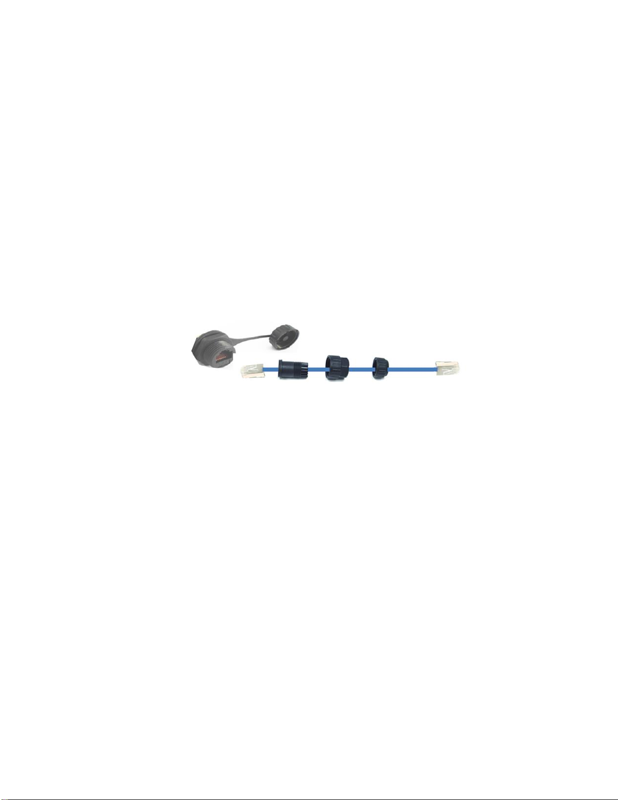
The PIS6095 package provides two Weatherproof Cable Connectors.
Step 1
: Feed the AC Input Power Cable Through the Waterproof Connector 1 and Plug It Into the AC Input PWR
and AC Power Port Accordingly. The AC Power Wire Color Code is as Follows: E= Green, N = White, L
= Black. Please follow your regional electrical power code. (if already preinstall, then go to Step 2)
Step 2
: Connect a first the PoE device to the PoE Port 1 using WECK0001 Waterproof Ethernet Connector Kit,
shown below:
Step 3
: Connect a Second Device, optionally a LAN device, to the PoE Port 2 and Used as a LAN port with
WECK0001. Or, Connect a Second PoE device to the PoE Port 2 if Connecting to Two Power Devices is
Desired.
Step 4
. Connect the AC and/or DC Power Devices (PD) to the Configured PIS6095 Port.
Step 5
. Connect the AC power cable, WPCK0001-3 Waterproof Power Cable Kit, to the Main AC Power Source to
power on the PIS6095. Please make sure you follow the power polarity based on the following color
Step 7.
To verify the AC and/or DC PD is Receiving Power, please check if AC Power LED and PoE Out LED are ON.
If the AC Power LED is not ON, please check the power source.
After you connect the power device with the Injector, PoE LED will turn ON. IF THE PoE OUT LED IS
NOT ON, PLEASE CHECK IF THE POWER DEVICE IS BASED ON THE POE PIN
CONFIGURATION, I.E., 1(+), 2(+), 3(-), 6(-).
W E C K 0 0 0 1 W a t e r p r o o f
E t h e r n e t C o n n e c t o r K i t
A s s e m b l y D i a g r a m

LinkPower PIS6095 Outdoor 30W Gigabit PoE Injector
Page 15 of 19
2.6.5 Pole Mounting the PIS6095 Outdoor PoE Injector
The Pole Mount Kit, MMK0001-XS, is an optional accessory.
2.7 PoE Injector and Cable Length Consideration
It is recommended to check the PoE equipment PoE cable length specification prior to
installation to ensure correct power is delivered to the PoE equipment. Using the wrong
voltage and/or exceeding PoE cable length may lower the products performance or in most
cases damage the product. When making your PoE cables, please adhere to TIA/EIA 568B
telecommunication cabling standard.
Ethernet network cables utilize pins 1, 2, 3, and 6 of an 8-pin RJ-45 connector. Equivalent
PoE cables should be utilized for reliable operation. STP type cables should always be used
in high EMI environment to minimize noise and maximize performance.

LinkPower PIS6095 Outdoor 30W Gigabit PoE Injector
Page 16 of 19
Network Type
Cable Type
10Base-T
4 Pair UTP/STP Cat 3, 5e, 6 cable, EIA/TIA-568-B.2 100-ohm (up to
100m)
100Base-TX
4 Pair UTP/STP Cat. 5e, 6 cable, EIA/TIA-568-B.2 100-ohm (up to 100m)
1000Base-TX
4 Pair UTP/STP Cat. 5e, 6 cable, EIA/TIA-568-B.2 100-ohm (up to 100m)
10Base-T and 100Base-TX standard specifies the cable length support up to 100 meters or
330 feet. Power delivery on the other hand limits the cable length according to your PoE
device specification. When utilizing proprietary PoE power scheme, check the voltage
tolerance of your PoE equipment. When in doubt, use 3VDC voltage attenuation per 25
meter of Cat 3, 5, 5e, or 6 cables. Using longer cable than the PoE equipment specified limit
may cause PoE equipment instability. Contact your PoE equipment manufacture for cable
length specifications.

LinkPower PIS6095 Outdoor 30W Gigabit PoE Injector
Page 17 of 19
Appendix I. Technical Specifications
Product Name
2.5Gbps 2-Port High-Power Port PoE Injector
Product Model
PIS6095
Connector Type
2x 2.5Gbps copper cable RJ45 ports
PoE Power Supply
Type
PoE power supply is four line pairs of twisted pair, the positive power supply
side is 1/2 or 4/5 line pair, the negative power supply side is 3/6 or 7/8 line pair
Network Medium
10BASE-T: 5 class UTP(≤100m)
100BASE-TX: 5 class or more UTP(≤100m)
1000BASE-TX: 5 class or more UTP (≤100m)
2.5GBASE-T :Cat6 or later UTP(≤100 meter)
Performance
Specifications
PoE output voltage: 48.0~50.4V
Working Speed:10/100/1000Mbps
Network Port Protection: meet the IEC61000-4-2(ESD)
MTBF: 100,000 hours
Network Protocols
and Standards
IEEE 802.3i 10BASET
IEEE 802.3u 100BASETX
IEEE 802.3x Flow Control
IEEE 802.1ab 1000BASET
IEEE802.3bz 2.5GBASE-T
IEEE 802.3bt DTE Power via MDI
Support 802.3bt PoE++ high power PoE standard, backward compatible with
IEEE 802.3af / IEEE 802.3at standard
LEDs Indicator
PoE working status
Power
Total system power: 100.8W
PIS6095 PoE output power: 90W
Input Voltage: 120V ~240V, Output Voltage: 48.0 - 50.4V
Dimension/Weight
LxWxH: 193.80mm x 117.60mm x 78.49mm (7.63x4.63x3.09 inch) / 4LB / 1.8kg
Working
Working Temperature: -30°~70°C, Storage Temperature: -20°~75°C
Working Humidity: 10% ~90%, non-condensing, Storage humidity:10%
~95%, non-condensing, Weatherproof to IP67 Compliance

LinkPower PIS6095 Outdoor 30W Gigabit PoE Injector
Page 18 of 19
Environment
Safety & EMC
CE mark, commercial, FCC Class A, RoHS
UL60950-1, TUV EN60950-1 Approved
Warranty
3 year warranty

LinkPower PIS6095 Outdoor 30W Gigabit PoE Injector
Page 19 of 19
Appendix II. Inscape Data Sales & Support Offices
For more information about Inscape Data Corporation products, applications, support, and for
a current sales office listing, visit our web site: http://www.inscapedata.com
U.S. Headquarters
Here’s how to reach us if you’d like to place an order or if you have questions or concerns
Telephone
Postal Mail
North and South America
Customer Service and Orders:
Main: +1-408-392-9800
Fax: +1-408-392-9812
Monday - Friday
9:00 AM - 5:00 PM
Pacific Time UTC -7:00
Inscape Data Corporation
2012 Hartog Dr.
San Jose, CA 95131, U.S.A.
Table of contents
Popular Laboratory Equipment manuals by other brands

Heidolph
Heidolph Hei-MIX Titramax 100 operating manual

Baoding Longer Precision Pump
Baoding Longer Precision Pump EasyPump Series manual

PASCO
PASCO AP-8209 instruction manual

Thermo Scientific
Thermo Scientific Neslab Merlin M 25 Installation, Operation, Basic Maintenance

COOK Medical
COOK Medical Flexipet Instructions for use

EIJKELKAMP
EIJKELKAMP 08.02 SAND / KAOLIN BOX operating instructions


Scientific Industries
Scientific Industries MULTI VORTEX-GENIE SI-M236 operating instructions

Idex
Idex Fast & Fluid Hercules user manual

CoolLED
CoolLED pE-800 quick start guide

Thermo Scientific
Thermo Scientific Invitrogen E-Gel G8000 quick start guide

Hanil
Hanil Ultra 5.0 operating manual

CORNING
CORNING LSE instruction manual