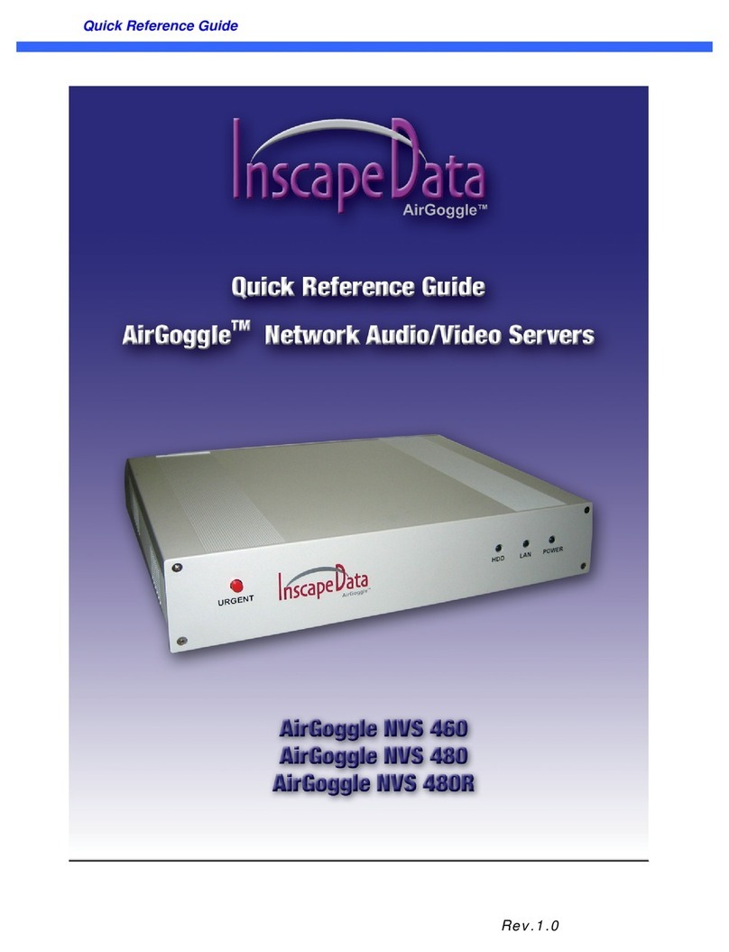
Inscape Data AirGoggle NVS 410 User manual

Copyright, 2004, All Rights Reserved
Inscape Data Corporation
AirGoggle
NVS 410
Network Audio/Video Server
User’s Manual
Inscape Data Corporation

NVS410 User’s Guide
-
--
-
2
22
2
-
--
-
NOTE
This equipment has been manufactured and tested to comply with the limits for a Class B
di
g
ital device, pursuant to part 15 of the FCC Rules. These limits are desi
g
ned to provide
reasonable protection a
g
ainst harmful interference in a residential installation. This
equipment generates, uses and can radiate radio frequency ener
g
y and, if not installed
and used in accordance with the instructions, may cause harmful interference to radio
communications. However, there is no
g
uarantee that interference will not occur in a
particular installation. If this equipment does cause harmful interference to radio or
television reception, which can be determined by turning the equipment off and on, the
user is encoura
g
ed to try to correct the interference by one or more of the followin
g
measures:
!Reorient or relocate the receiving antenna.
!Increase the separation between the equipment and receiver.
!Connect the equipment into an outlet on a circuit different from that to which the
receiver is connected.
!Consult the dealer or an experienced radio/TV technician for help.
NOTE
NVS410 is designed for indoor use only. When using NVS410 outdoors or in an environment
that exceeds the limited range, you must separately use a water-resistant case.
Be careful not to cause any physical dama
g
e by droppin
g
or throwin
g
the NVS410 A/V Server.
Especially keep the A/V server out of reach from children.
Do not disassemble NVS410. The unit will be excluded from After Service when disassembled.
Use only the power adapter provided with the NVS410.
If you would like to use the NVS410 A/V server for security and/or monitoring, please check the
legal regulations within the country.

NVS410 User’s Guide
-
--
-
3
33
3
-
--
-
Caution
Any changes or modifications in construction of this device that are not expressly
approved by Inscape Data could void the user’s authority to operate the equipment.
Caution
None of the parameters in administrative pa
g
e should be chan
g
ed while NVS410 is
recording video or while you are playing back recorded video from NVS410.

NVS410 User’s Guide
-
--
-
4
44
4
-
--
-
1. Introduction................................................................................................................................................... 5
1.1. Overview........................................................................................................................... 5
1.2. Features of NVS410.......................................................................................................... 5
1.3. Applications of NVS410 ..................................................................................................... 5
2. Product Description....................................................................................................................................... 6
2.1. Contents........................................................................................................................... 6
2.2. Content Preview................................................................................................................ 6
2.3. Physical description........................................................................................................... 7
2.4. PC Requirements.............................................................................................................. 9
2.5 Quick Installation Guide...................................................................................................... 9
3. Connecting the NVS410.............................................................................................................................. 12
3.1. Connection to a LAN ....................................................................................................... 12
3.2. Connecting to xDSL Modem ............................................................................................ 13
3.3. Connecting to Cable Modem............................................................................................ 14
4. IP-Installer .................................................................................................................................................. 16
4.1. Main window of IP-Installer.............................................................................................. 16
5. Configuring the NVS410 in Administrative Mode..........................................................................................17
5.1. Log On............................................................................................................................ 17
5.1.1. Using Internet Explorer......................................................................................17
5.1.2. Log on from “NVR100 Software” ..........................................................................17
5.1.4. User ID and Password ......................................................................................18
5.2. Basic Setup..................................................................................................................... 19
5.3. Network Configuration..................................................................................................... 22
5.4. User Admin & Time Setup................................................................................................ 25
5.5. Sensor & Capture Setup.................................................................................................. 28
5.6. Alarm Device Setup......................................................................................................... 30
5.7. Motion Region Setup....................................................................................................... 31
5.8. PTZ Setup ...................................................................................................................... 33
5.9. Upgrade & Reset............................................................................................................. 35
5.10. Status Report ................................................................................................................ 37
6. Tips for Using NVS410................................................................................................................................38
6.1. Relay output and Sensor input ............................................................................... 38
6.2. Trouble Shooting............................................................................................................. 39
6.3. How To Upgrade Your NVS410 System............................................................................ 41
Table of Contents

NVS410 User’s Guide
-
--
-
5
55
5
-
--
-
1. Introduction
1.1. Overview
The AirGoggle NVS410 is a state-of-the-art 1-channel A/V server, which transmits both video and audio data in
real time with high-resolution and frame rate. This is possible through MPEG-4 CODEC technology, which
provides data transmission at high compression rates and data resolution via networks. The NVS410 is IP
addressable and can be controlled and monitored from a remote location through an IP address. Unlike CCTV
or DVR, the NVS410 is easy to install and very cost effective. Based on Embedded Software Solution
(Embedded Web Server, Embedded Streaming Server, Network Protocol), the NVS410 ensures high
performance, stability, and integration of various Internet solutions.
1.2. Features of NVS410
"1 channel real time Video/Audio streaming based on MPEG-4 video and ADPCM audio.
"1 channel Bi-directional Audio between NVS410 and Client PC for two-way communication
"The viewer assisted recording and playback functions.
"Motion detection – Up to 3 motion detection regions.
Motion detection can initiate video recording, which is sent to the user through FTP and (or) E-mail.
"Resolution :
NTSC Video : 640x240(Half VGA), 320x240(QVGA)
PAL/SECAM : 704x288, 352x288(CIF)
"Remote Software Upgrade over Network
"Remote P/T/Z control : Canon VC-C4/C4R etc.,
"Ease of use and convenient user interface.
1.3. Applications of NVS410
"Security surveillance (buildings, stores, factories, parking lots, banks, government facilities, military, etc.)
"Real time Internet broadcasting (resort areas, events, etc.)
"Remote monitoring (hospitals, kindergartens, traffic, public areas, etc.)
"Teleconference (Bi-directional video conference)
"Remote Learning
"Weather and environmental observation

NVS410 User’s Guide
-
--
-
6
66
6
-
--
-
2. Product Description
2.1. Contents
Open the package and check that you have the following:
Components Description Remarks
NVS410 A/V server Main Unit
AC Power Adapter Input : 100~250V 50-60Hz
Output : +12V, 1.0A
AC Power Cable AC 250V, 10A~16A
LAN Cable 2m LAN cable – Crossover type For direct connection
between the server and PC.
CD-ROM Product Software & User’s Guide
Quick Install Guide Easy to follow quick install guide
2.2. Content Preview
NVS410 IP-Installer NVR100 Software
NVS410
Network A/V server
IP address management
PC software
Full feature NVR100 PC software to
view and record A/V streaming data
and control the mode of operation.

NVS410 User’s Guide
-
--
-
7
77
7
-
--
-
2.3. Physical description
2.3.1. Front panel
Figure 2-1. Front panel of NVS410
Status indicator:
As shown in Figure 2-1, there are three status indicator LEDs. From left to right they are HDD,
LAN and Power.
HDD : This feature is not enabled for this model.
LAN : Link indicator, continuous green light means that LAN is in normal state. When there is
traffic on the LAN, orange light flickers.
Power : Status indicator shows the status of the NVS410 in three different colors.
Green : The green light indicates that the NVS410 is operating properly. If the green light is
continuously on, it means that the NVS410 is ready to transmit data via network. If
the green light blinks, it means that there is traffic between LAN and NVS410.
Red : The red light indicates that the hardware of the NVS410 is not operating properly.
Orange : The orange light indicates that the software of the NVS410 is not operating
properly.
When applying power to NVS410, power indicator temporarily li
g
hts on with red
color and then returns to green. This is the normal condition.

NVS410 User’s Guide
-
--
-
8
88
8
-
--
-
2.3.2. Rear panel
Figure 2-2. Rear Panel of NVS410
#Power : Power input of NVS410. 12V/1A
#MIC/Line In : It is used to connect an external audio source or microphone to NVS410
#SPEAKER/Line Out : It is used for connecting external speakers with built in amplifier. Audio from
remote site is output through Line out in bi-directional audio mode. Use Standard stereo
headphone jack for the connection.
#RELAY : It is used for connecting external alarm generators such as sirens and flashing lights.
When activated, relay output configures a closed circuit. Two Relay outputs(A, B) are provided.
#SENSOR : There are provisions for 2 alarm sensor device connections. They are used for
connecting external alarm sensors such as the infrared sensors, heat sensor, magnetic sensors, etc.
#RS-485 : It is used for connecting P/T/Z device having RS-485 interface standard.
#RS-232(9 pins) : It is used for connecting P/T/Z device having RS-232 interface standard
(Either one of RS-232 or RS-485 can be used as a P/T/Z interface at one time.)
#VIDEO-IN : Video input (composite NTSC, PAL, SECAM)
#VIDEO-OUT : Video input (composite NTSC, PAL, SECAM) for bypassing signal from VIDEO-IN
#LAN : 10Base-T Ethernet connector. Connects NVS410 to 10Mbps Ethernet
#Reset - Enable factory default setting. Doing so will erase all previously entered
parameters and replace it with factory default settings. Not labeled for security
reasons. Shown above in Figure 2-2 circled in red.

NVS410 User’s Guide
-
--
-
9
99
9
-
--
-
2.4. PC Requirements
Audio/Video monitoring and recording can be achieved with the use of NVR100 Software program running on a
PC. The Minimum PC requirement follows:
Minimum Recommended
CPU Pentium III 700 Pentium IV 1.2G above
Memory 128 MB 256MB or more
Operating system*Windows 98 SE. Windows 2000 or later
Web browser Internet Explorer 5.0 Internet Explorer 5.0 or later
Video Resolution 1024 X 768 1600 X 1200
Network 10 Base-T Ethernet 10/100 Base-T Ethernet
* Operating Systems supported : Windows 98 Second edition,
Windows NT Workstation 4.0 (SP 5.0 OVER)
Windows 2000 Professional
Windows XP Professional / Windows XP Home Edition
2.5 Quick Installation Guide
Brief information for rapid installation is provided in this section. For more detailed information you are
recommended to refer to pertinent documentations provided with the product or refer to Inscape Data’s home
page (http://www.InscapeData.com).
1. Apply Power to the AirGoggle NVS410.
2. Connect the AirGoggle NVS410 Audio/Video Server to your PC or Network via one of the following
method.
i. Connect your PC and NVS410 using a crossover LAN cable.
ii. Connect the AirGoggle NVS410 and configuration PC to a Hub or Switch via normal LAN
cable.
3. Install “IP installer” and “NVR100 Software” on your PC.
Detailed information for installing these programs can be found in [IP-Installer User’s Guide] and
[NVR100 Software User’s Guide],respectively.
4. Assign an IP address to NVS410 via the IP installer software.
Identify the type of the network environment and set up an IP address accordingly. Detailed process of

NVS410 User’s Guide
-
--
-
10
1010
10
-
--
-
setting up the IP address can be found in [IP-Installer User’s Guide].If the network type is xDSL or
Cable modem you will need supplementary information provided by your ISP.
5. Connect to NVS410 in Administrator Mode for initial parameter set-up.
All parameters are set to factory default state when NVS410 is delivered to you. Detailed information
of using administration mode can be found in section 5 [5. Configuring the A/V Server in
Administrative Mode]. The parameters in the following table should be set-up with proper values.
Detailed information for the parameters in Administrator Mode can also be found in section 5 [5.
Configuring the A/V Server in Administrative Mode]
NOTE: The set-up values are preserved even if the power is turned off.
Menu Parameter Setup value Factory default value
User Admin
and Time
Setup
Administrator name &
password
For security reasons, you are
recommended to change these
values from factory default
settings. Please note these
new values in a secure place.
Username : root
Password : dw2001
User Admin
and Time
Setup
Current Time Input correct time in this field. 2001/1/1
Video Size Define the video transmission
resolution.
Max Upload Rate
This value should be below the
network speed in which the
NVS410 is connected to.
Frame Rate Number of frames transmitted
per second.
Basic
Setup
Video Rate Video transmitted bandwidth
allowed
Must be Set Manually
6. Connect audio/video sources, sensors, and output devices to the NVS410 accordingly.
NOTE: NVS410 may not function properly if there is no video and audio input. Please Reference to
the following table for proper functional setup. You have to connect Video source.

NVS410 User’s Guide
-
--
-
11
1111
11
-
--
-
Connectors Function Description Number of Ports
Video In Input video
connector
Analog video outputs from analog
CCTV camera, DVD, TV etc.,
(NTSC/PAL/SECAM)
1
Line In/Mic Audio in Microphone or output from external audio
devices. 1
Line Out Audio out for
speaker
When in bi-directional audio mode, Audio
signal from remote site is available from this
connector. Use speaker with amplifier.
1
Sensor Alarm Sensor Input Example: IR sensor, Motion Sensor, Smoke
Detector, and Many more type of sensor. 2
RELAY Output External Alarm Or
Alerting devices Example: Siren, Beacon, External Relay. 2
RS485 PTZ device control Output signal controlling an P/T/Z device 1
RS232 PTZ device control Output signal controller an P/T/Z device
(Canon VC-C4/C4R) 1
LAN/10 Base T Ethernet Interface Connect the NVS410 to an Ethernet Hub,
Bridge, or Router 1
RESET
Return the NVS410
to factory default
setting
Once pressed, it will reset all values of
NVS410 to factory default setting. 1
VIDEO OUT Video Output
Connector
Bypasses the input video to feed into
external video viewers or recorders. 1
5. Video connection to NVS410
You can connect to NVS410 in video mode by running “NVR100 Software” program on your PC. Detailed
information of using “NVR100 Software” can be found in [NVR100 Software User’s Guide].

NVS410 User’s Guide
-
--
-
12
1212
12
-
--
-
3. Connecting the NVS410
NVS410 supports LAN, xDSL, and Cable modem. It also supports shared IP networks, where many internal
network clients share a single public IP address. Refer to [IP-Installer User’s Guide] for details of setting the
IP address for the NVS410.
3.1. Connection to a LAN
Typically the NVS410 is connected to a network as follows:
Figure 3-1. Typical NVS410 network connection
1. After it is powered on, connect the NVS410 to a LAN.
2. Assign an IP address to the NVS410 by using the IP-Installer. Make sure the PC running the IP-Installer is
in the same subnet as NVS410.
3. Check if video streams can be viewed with NVR100 software.

NVS410 User’s Guide
-
--
-
13
1313
13
-
--
-
3.2. Connecting to xDSL Modem
1. After power on, connect the NVS410 to a PC or Notebook via a crossover CAT 5 network cable provided
with the system.
2. Setup network parameters by running “IP-Installer.”
Figure 3-2. Direct connection using crossover LAN cable
Figure 3-3. Connecting the NVS410 to xDSL
3.Remove the LAN crossover network cable to the PC or Notebook and connect the NVS410 to the
network using standard LAN network cable. Verify the connection by using the NVR100 network video
software to see if the video source is viewable.
②
②②
②
Regular LAN or crossover
LAN cable

NVS410 User’s Guide
-
--
-
14
1414
14
-
--
-
3.3. Connecting to Cable Modem
1. Apply power and connect the PC and NVS410 together via the crossover cable provided with the system.
2. Setup network parameters by running “IP-Installer”. (Refer to Figure 3-4).
Figure 3-4. Direct connection using crossover LAN
3. Remove the crossover cable and connect the NVS410 to the network using standard LAN cable as
shown in Figure 3-5. Check if you can receive video using the viewer program.
In most cases when connecting the NVS410 to a xDSL Modem, a standard Ethernet
network cable is required. But since a few xDSL Modems uses crossover connections,
please verify the interface with your Modem manufacturer.
In most cases when connecting the NVS410 to a Cable Modem, a standard Ethernet
network cable is required. In some cases a crossover connection may be needed.
Please verify the interface with your Cable Modem manufacturer.

NVS410 User’s Guide
-
--
-
15
1515
15
-
--
-
Figure 3-5 Connecting the NVS410 to a Cable Modem
Regular LAN cable
or crossover cable

NVS410 User’s Guide
-
--
-
16
1616
16
-
--
-
4. IP-Installer
NVS410 is IP addressable therefore needs an IP address for connection to the network. Inscape Data’s IP-
Installer is a PC program developed to assign IP addresses and network parameters to digital video security
network products such as Network Video Camera and Network Video Server from Inscape Data. IP-Installer is
contained in the CD supplied with your product.
Detailed information of Installing and running IP-installer can be found in [IP-installer user’s guide]
4.1. Main window of IP-Installer
Figure 4-1. IP-Installer

NVS410 User’s Guide
-
--
-
17
1717
17
-
--
-
5. Configuring the NVS410 in Administrative Mode
5.1. Log On
There are 2 methods of login into the NVS410 administrative console. One is through standard internet
browser and the other is through “NVR100 Software” program.
5.1.1. Using Internet Explorer
You can log on to the server by clicking admin mode button or from your internet browser.
Type in the following URL in your favorite web browser.
http://[NVS410 IP address]/admin.htm
Example: http://172.16.64.33/admin.htm
If you changed the HTTP port from default value you can login by typing in:
http://[NVS410 IP address]:[port]/admin.htm
Example: http://172.16.64.33:8080/admin.htm
5.1.2. Log on from “NVR100 Software”
Select a video channel in the viewing window of “NVR100 Software” using your computer mouse. Selected
video channel will be highlighted. Click button on the right side of the display screen, which is shown in
Figure 5-1, circled in red.
Figure 5-1. “NVR100 Software”

NVS410 User’s Guide
-
--
-
18
1818
18
-
--
-
5.1.4. User ID and Password
On the initial login to NVS410, a windows prompt for User Name and Password appears as shown
below in Figure 5-2.
Figure 5-2. Log On Screen
Factory default User Name and Password are set as ‘root’ and ‘dw2001’, respectively. Click on “OK” button to
enter into the Basic Setup page of Admin Mode. If you have changed the username and password of the
Administrator, you must log on with the changed username and password.

NVS410 User’s Guide
-
--
-
19
1919
19
-
--
-
5.2. Basic Setup
Setup the basic parameters of the NVS410. The web interface is shown below in Figure 5-3.
"Language Selection:You can select a language in the admin page.
-Supported languages: English, Korean, Japanese, Chinese, Spanish
Figure 5-3. Basic Setup

NVS410 User’s Guide
-
--
-
20
2020
20
-
--
-
"System Name
It is the name of the NVS410. It is the same as the one set-up by the IP-installer. You can reassign the
system name in admin mode.
"Audio Input Selection
-Select the type of input audio. Line-In is used for connection of external audio devices and Mic
is used if the external device is a microphone.
-Input Gain: Selectable gain for the input line.
"Video Quality & Bandwidth Control
- Input Video Source : Select the analog video standard for input. Select one from NTSC, PAL, SECAM.
- Video Size : Select a video size for transmission. Allowed video sizes are different for each video standard.
- NTSC(30 frames/sec Max.) : 320x240 / 640x480.
- PAL (25 frames/sec Max.) : 352x288 / 704x576.
- SECAM (25 frames/sec Max.) : 352x288 / 704x576.
#Max upload rate
oAssign maximum bandwidth of the uplink for the network connected to NVS410.
#Frame rate
oAssign number of video frames transmitted for each second. You can improve picture quality by
lowering frame rate for the same bandwidth.
#Video rate
oAssign bandwidth for transmitting video data.
#Audio rate
oAssign bandwidth for transmitting audio data. Audio data is not transmitted if you select “NA”
"Check
After you finish setup of video and audio for all the channels, click on this button to obtain the possible
maximum number of users (Possible Max Users) and network bandwidth margin (Remained) remaining.
The Check tool will calculate the number of users able to view the video stream without any quality
degradation or network congestion.
"Possible Max Users
It shows the number of maximum simultaneous connections for the network connection set-up.
Table of contents
Other Inscape Data Server manuals
Popular Server manuals by other brands

Asus
Asus AP1400R installation guide
Dell
Dell 0G8DW Installation and service manual

Amare Musica
Amare Musica Diamond Series owner's manual
Silicon Graphics International
Silicon Graphics International SGI UV 30 user guide
CyberData
CyberData 11146 Operation guide
Lantronix
Lantronix SecureBox SDS1100 user guide

