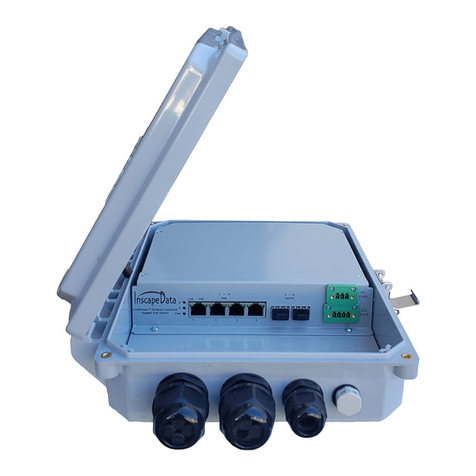
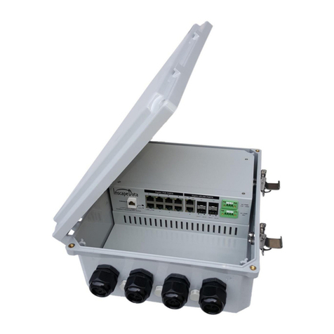
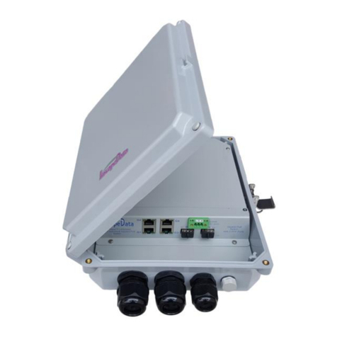
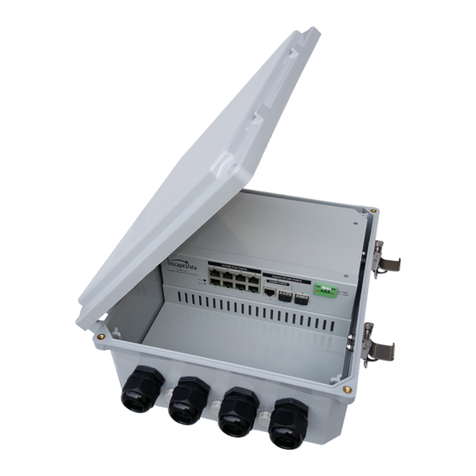
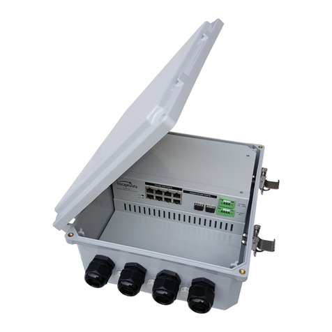
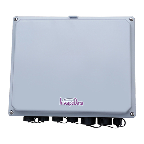
Inscape Data Link Power LPS3400-T1 Series User manual

Page | 1
Link Power LPS3400-T1 Series
Outdoor Industrial 4-Port Managed
PoE Network Switch with 2 SFP
Uplink Ports
USER MANUAL
Inscape Data Corporation
1620 Oakland Road, STE D101
San Jose, CA 95131
U.S.A.
© Copyright 2016, Inscape Data Corporation, All Rights Reserved. LinkPower, AirEther, AirGoogle,
and Inscape Data are trademarks of Inscape Data Corporation
Disclaimer: While every effort is made to ensure the information given is accurate, Inscape Data
Corporation does not accept liability for any errors or mistakes which may arise. All information and
specifications are subject to change without notice.

Page | 2
Certification
Inscape Data Corporation certifies that this product met its published specifications at time of
shipment from the factory.
FCC Statement
This equipment has been tested and found to comply with the limits for a Class A digital device,
pursuant to Part 15 of the FCC Rules. These limits are designed to provide reasonable
protection against harmful interference when the equipment is operated in a commercial
environment. This equipment generates, uses, and can radiate radio frequency energy and, if
not installed and used in accordance with the instruction manual, may cause harmful
interference to radio communications. Operation of this equipment in a residential area is likely
to cause harmful interference in which case the user will be required to correct the interference
at his own expense.
The user is cautioned that changes and modifications made to the equipment without approval
of the manufacturer could void the user's authority to operate this equipment.
The manufacturer is not responsible for any radio or TV interference caused by unauthorized
modifications to this equipment. Such modifications could void the user’s authority to operate
the equipment.
Industry Canada Statement
This Class A digital apparatus complies with Canadian ICES-003.
CE Statement
This product complies with the European Low Voltage Directive 73/23/EEC and EMC Directive
89/336/EEC as amended by European Directive 93/68/EEC.
Warning: This is a class A product. In a domestic environment this product may cause radio
interference in which case the user may be required to take adequate measures.
UL Recognized Statement
The power supply of this product has been investigated using applicable construction and
performance requirements by UL, and when installed in accordance with the manufacturer’s
installation instructions, should provide a safe, code-compliant installation.

Page | 3
Safety Summary
The following general safety precautions must be observed during all phases of operation of this
instrument. Failure to comply with these precautions or with specific warnings elsewhere in this
manual violates safety standards of design, manufacture, and intended use of the instrument.
Inscape Data Corporation assumes no liability for the customer’s failure to
comply with these requirements.
Before Applying Power
Verify that the product is set to match the available line voltage and all safety precautions are
taken.
Over Temperature Warning
To prevent the switch from overheating, do not operate it in an area that exceeds the maximum
recommended ambient temperature of (75°C). To prevent product cooling restriction, allow at
least 3 inches (7.6 cm) of clearance around the product after installation.
Ground the Instrument
To minimize shock hazard, the instrument chassis and cabinet must be connected to an
electrical ground. The instrument must be connected to the ac power supply mains through a
three-conductor power cable, with the third wire firmly connected to an electrical ground (safety
ground) at the power outlet. For instruments designed to be hard-wired to the ac power lines
(supply mains), connect the protective earth terminal to a protective conductor before any other
connection is made. Any interruption of the protective (grounding) conductor or disconnection of
the protective earth terminal will cause a potential shock hazard that could result in personal
injury.
When installing the unit, always make the ground connection first and disconnect it last.
Jewelry Removal Warning
Before working on equipment that is connected to power lines, remove jewelry (including rings,
necklaces, and watches). Metal objects will heat up when connected to power and ground and
can cause serious burns or weld the metal object to the terminals.
Do not Operate in Explosive Atmosphere
Do not operate the product in the presence of flammable gases or fumes.

Page | 4
Chassis Power Connection
Before connecting or disconnecting ground or power wires to the chassis, ensure that power is
removed from the device. To ensure that all power is OFF, locate the circuit breaker on the
panel board that services the device, switch the circuit breaker to the OFF position, and tape the
switch handle of the circuit breaker in the OFF position.
Work During Lightning Activity
Do not work on the system or connect or disconnect cables during periods of lightning activity.
Comply with Local and National Electrical Codes
Installation of the equipment must comply with local and national electrical codes
Do Not Exceed Input and Output Ratings
Do not operate the product to exceed the power input and output ratings.
This product Conforms to the following safety standards
Specification
Description
Regulatory Compliance
Products with the CE Marking are compliant with the
89/336/EEC and 73/23/EEC directives, which include the safety
and EMC standards listed.
Radiation
CE mark, commercial
FCC Part 15 Class B
VCCI Class B
EN 55022 (CISPR 22), Class B
Safety
CE Mark Commercial
CE/LVD EN60950
UL 60950-1, TUV EN60950-1, IEC60950-1 Approved

Page | 5
Table of Contents
Packing List (In The Box) .............................................................................................................................................6
Product Description.......................................................................................................................................................7
Product Features............................................................................................................................................................7
Installation.....................................................................................................................................................................7
Top Cover......................................................................................................................................................................8
IP Web Management Login:..........................................................................................................................................8
Control Panel Diagram..............................................................................................................................................8
LED Indicator Description Table: .................................................................................................................................9
Grounding Protection: ...................................................................................................................................................9
Grounding the Switch by Using the AC Power Cord....................................................................................................9
Power Redundancy & UPS Input ................................................................................................................................10
RESET Switch (System Reset):...................................................................................................................................11
Installation & Mounting: .............................................................................................................................................11
Connector Layout Diagram: ........................................................................................................................................12
Waterproof Ethernet, Fiber Optics, & Power Connector Assembly Diagram.............................................................12
Optional Accessories...................................................................................................................................................12
Product Dimensions:....................................................................................................................................................13
Wall Mount & Pole Mount :........................................................................................................................................13
Product Specifications:................................................................................................................................................14
Contacting Inscape Data Sales and Support Offices....................................................................................................15

Page | 6
Packing List (In The Box)
Each package includes the following items:
•LPS3400AFM-T1 or LPS3400ATM-T1 (1)
•WM0001 Wall Mounting Kit (1)
•MMK0001-L Pole Mount Kit (Optional Accessory)
PART #: MMK0001-L
To order online, https://www.inscapedata.com/store
•Top Cover Screws & Hole Fillers (4)
•AC Power Cord with one 3-Terminal AC Power Connector (1)
•DC Power Cord with one 4-Terminal DC Power Connector (Optional Accessory)
PART #: DPCK0001
To order online, https://www.inscapedata.com/store
•Web Management Manual:
Download from the following link:
https://www.inscapedata.com/pdf/LPS3000_Web_Management_ManualV2.0.pdf
•User Manual (1)
•Warranty Sheet (1)

Page | 7
Product Description
LPS3400-T1 Series Outdoor Industrial PoE Switch features with four PoE Ethernet ports and comply to
10/100/1000BaseT(X), IEEE802.3af/at PoE and two Gigabit SFP fiber optics uplink interfaces. Each of the
PoE ports supplies DC power up to 15.4W for 802.3af and 30W for 802.3at, PoE Plus. The transfer data is
up to 120Km from SFP fiber port to a control center. Additionally, the product also features with an anti-
electromagnetic interference designed for harsh outdoor applications, and the 3KV network port surge
protection adapts to harsh outdoor environment and ensures the reliability of the uninterrupted PoE
operations. The system is rated at IP68, and the system is able to operate under -30˚ ~ +70˚ C temperature
range.
Product Features
1. The system supports DUAL POWER INPUT REDUNDANCY
2. Comply to IEEE 802.3, IEEE
802.3u, IEEE 802.3z, IEEE 802.3ab, IEEE 802.3x, IEEE 802.1D, IEEE
802.3at, IEEE 802.3af, IEEE 802
.
1Q
IEEE
802.1p, IEEE 802.1x, IEEE 802.1W, SNMP, IGMP
s
t
andards
3. 10/ 100/ 1000M self-sensing RJ45 port, support PoE power supply f
unc
t
ion
;
All ports support auto-
flip (Auto
MD
I/
MD
I
X)
;
4. Each PoE port can provide power up to 15.4W per IEEE802.3af standard and 30W per IEEE802.3at
standard
;
Supply power for powered devices compatible with
I
EEE802
.
3a
f/at;
5. Support IEEE802.3x full duplex flow control and duplex
backpressure
flow
con
t
rol
;
6. 8.8G backplane
bandwid
t
h
;
7. 1K MAC address
t
able
;
8. Its 3KV network port surge protection can adapt to harsh outdoor
environmen
t;
Under the
temperature of -30˚~ +70˚C, working at a full load 144W for IEEE802.3at
;
9. The four gigabit SFP fiber ports are capable of high bandwidth and for up to 120KM long distance
t
ransmission.
10. Dual redundancy power input, AC and DC, (More than 50V DC recommended when used PoE+ output)
Installation
a. Before installation, please ensure the following:
1) All PD devices, i.e., PoE Clients, meet the power requirement of the connecting devices.
2) All PD devices, i.e., PoE Clients, match with the power receiving device power pinout
specification (1/2+ & 3/6-)
b. Connect the power cable to a power source, 110 ~ 240V AC, the 48V DC is optional and can be
used as the backup power or primary power when the AC power is not available. Then the
switch will automatically initialize, and LED lights status will display as following:
i. Except the POE port lights, all the other lights will go through the process of “on-off-on-
off”, which means the installation is successful.
ii. Power LED remains ON
c. Connect the network devices with network cables to the POE switch port though the waterproof
connectors, then secure the Top Cover with the four screws to the Bottom Case
d. After the Ethernet and/or fiber optics network devices are connected, please refer the LED
Indicator Description Table Below on Page 6
e. With the dual redundancy power input, you can connect a DC power source with the 4-Pin
DC Connector to the DC Input Connector simultaneously with the AC Input. When
connected, the DC Input operates as a backup power.
f. Lastly, please make sure you connect the Grounding Wire to earth ground, e.g., ground rod
(see Page 7 for details).

Page | 8
Top Cover
To connect the wires, you are simply to open the top cover by the latch. To install and connect the wire,

please follow the connector assembly diagram on the next page. Please note the following IP weatherproof
rating, when close the top cover:
1. Closing the top cover by latch, the weatherproof IP rating is IP66
2. Closing the top cover by 4 screws, included in the package, the weatherproof IP rating is IP68
Please close the top cover based on the required weatherproof condition per your installation.
IP Web Management Login:
All network ports of this device support WEB management equipment, IP management by default 192.168.2.1,
subnet mask: 255.255.255.0, the default gateway: 192.168.2.254. The administrator of the PC as long as you can
communicate with the equipment management.
Default IP Address: 192.168.2.1
Default login user: “admin” and login password: “system”.
For more IP management details, please read IP Management User’s Manuels provided online or download the manual from the
following link:
•https://www.inscapedata.com/pdf/LPS3000_Web_Management_ManualV2.0.pdf
•CLI Configuration User Manual –
http://www.inscapedata.com/manual/LinkPower_CLI_Configuration_User_Manual.pdf
•Console Port Setup Manual –
http://www.inscapedata.com/manual/LinkPower_Console_Port_Setup_Manual.pdf
Control Panel Diagram

Page | 9
LED Indicator Description Table:
Indicator
Status
Description
SYS
Indicator:
POWER
Green LED ON
Power On, Normal
LED OFF
Power OFF
1000M
Indicator:
Link
OFF
No Connected PD or Power OFF
Yellow LED Blink
Data transmission properly
Yellow LED ON
Connected with 1000Mbps network device
OFF
No connected PD
PoE
Indicator:
PoE
Green LED ON
Connected PD Device, working properly
Green LED Blink
Short circuit or current overload
OFF
No Connected PD or Power OFF
L/A Indicator: Link/Act
Green LED Blink
Data transmission properly
Green LED ON
Connection is OK and data is being sent and received.
OFF
No data connected
NOTE: All PoE ports of PD devices are complying with IEEE802.3af standard
Grounding Protection:
The system provides the following way to ground the equipment for safety and protection of the system. It is
highly recommended that you’re to perform both grounding procedures for maximum safety and protection of
your equipment. However, at least of the grounding MUST be performed, otherwise any product damage caused
by improper or no grounding will not be covered under warranty.
Grounding the Switch by Using the AC Power Cord
You MUST ground the switch through the AC wire of the power cord. Please make sure that:
1. The GREEN COLOR WIRE of the power cord extension is used as a PE (Protective Earth) terminal, Figure 5,
Aka, Equipment Grounding Conductor MUST BE CONNECTED TO A GROUND CONTACT IN A POWER
OUTLET.
2. The power cord is securely connected to the power outlet at the premise.
3. The ground contact in the power outlet is securely connected to the ground in the power distribution
room or on the AC transformer side.
4. If the ground contact in the power outlet is not connected to the ground, report and resolve the problem
and reconstruct the grounding system.
NOTE: PRODUCT DAMAGE CAUSED BY IMPROPER OR NO GROUNDING WILL NOT BE COVERED UNDER WARRANTY!
6 FT AC Power Cord:
White (W) –AC/N
Green (G) –Ground
Black (B) –AC/L

Page | 10
Wire Color Coding for Three-Screw Fixing Wire Terminal Coupler
AC Power Cable:
1. White (W) –AC/L
2. Green (G) –Ground
3. Black (B) –AC/N
3-Terminal AC Connector Set
DC Power Cable:
1. White (W) –Positive
2. Green (G) –Ground
3. Black (B) –Negative
4-Terminal DC Connector Set
Figure 5 GREEN COLOR WIRE of Both AC/DC Power Cords Is Used for Grounding
Power Redundancy & UPS Input
The switch offers dual power redundancy, i.e., AC & DC input. There are two power inputs, as shown below
diagram:
When the AC input is connected, the AC is the main power input to the switch. To enable the power redundancy,
you connect the DC power to the 4-Pin Terminal with a 48V DC and up to 57V DC power source. After the DC is
connected, the power redundancy is automatically enabled. In general, to use a 48v DC UPS (Uninterrupted
Power Supply) is highly recommended. A 48V DC UPS can be either an AC to DC UPS or solar-powered DC backup
UPS.
Once the DC power is connected, the DC power functions as backup power. If the AC is not used and the DC power
is connected, then the DC power functions as the main power. When the DC power is used as the main power, the
actual power required will be based on the total power consumption fo the connected devices. For example, if
there are two high power devices with 60W each and two low power devices with 10W each. Then, the total
power consumption is 150W, including the system power consumption, i.e., the switch, and this means it requires
the DC battery to provide at least 3.13A DC power.
Please note, the DC Power Cord Kit, Part # WPCK-004, is an optional accessory.

Page | 11
RESET Switch (System Reset):
There are two ways to reset the system, i.e., software reset and hardware reset, described as follow:
1. Software Reset: Login to the Switch via WEB management equipment, IP management by default IP
Address: 192.168.2.1, Default login User Name: “admin” and Password: “system”, then click ''Maintenance
''>''Factory Defaults'', followed screen will appear:
Please click ''Yes'' to restart the switch.
2. Hardware Reset:
To perform a hard reset of the system, the Reset Switch is located on the left side of PoE 1 Ethernet
Connector, and please hold and press the RESET Switch for 9 seconds. The system will reset automatically. Please
be very cautious about the internal wires and cables and DO NOT CHANGE or INTERFERE ANY OF THE INTERNAL
WIRES AND CABLES TO PREVENT DAMAGES TO THE SYSTEM.
Installation & Mounting:
You can mount the system with one of the two ways:
1. Wall Mount
Wall Mount Kit, Standard Accessory
2. Pole Mount
(Optional Accessory, MMK001 Pole Mount Kit)

Page | 12
Connector Layout Diagram:
Support Cable Gland and Conduit Connectors
The Hole Size: 1 Inch Diameter
Waterproof Ethernet, Fiber Optics, & Power Connector Assembly
Diagram
Plastic Plug
Note: The Sealing Insert comes with one and three holes. The Plastic Plug MUST be used to cover the Sealing Insert, if
any of the hole is not used in order to maintain waterproof of the connector.
Optional Accessories
The following optional accessories can be order if required:
1. Mast/Pole Mounting Kit (Part No: MMK0001-L)
2. SFP Duplex 1.25Gbps 3.3V Single-Mode Transceiver (Part No. SFP-SM-LC20-DDM)
3. SFP Duplex 1.25Gbps 3.3V Multimode Transceiver (Part No. SFP-MM-SJ8512-X5PSOS-DDM)
4. DPCK0001 DC Power Cord Kit (Part No. DPCK0001)
Open Cut for
Cable Insert
Connector Assembly Diagram

Page | 13
DPCK0001 DC Power Cord Kit
Product Dimensions:
Wall Mount & Pole Mount :

Page | 14
Product Specifications:
ELECTRICAL PIN OUT DIAGRAM

Page | 15
Contacting Inscape Data Sales and Support Offices
For more information about Inscape Data Corporation products, applications, support, and for a current sales office
listing, visit our web site: http://www.inscapedata.com
U.S. Headquarters
Here’s how to reach us if you’d like to place an order or if you have questions, concerns, or need support
Telephone
Postal Mail
North and South America
Customer Service and Orders:
Main: +1-408-392-9800
Fax: +1-408-392-9812
Monday - Friday
9:00 AM - 5:00 PM
Pacific Time UTC -7:00
Inscape Data Corporation
1620 Oakland Road, Suite D101
San Jose, CA 95131
U.S.A.
Table of contents
Other Inscape Data Switch manuals

Inscape Data
Inscape Data Link Power LPS1000 User manual

Inscape Data
Inscape Data Link Power LPS2400 User manual

Inscape Data
Inscape Data Link Power LPS3800-T1 Series User manual

Inscape Data
Inscape Data Link Power LPS3800-T2 Series User manual

Inscape Data
Inscape Data Link Power LPS2802-T1 Series User manual

Inscape Data
Inscape Data Link Power LPS1800-T1 User manual

Inscape Data
Inscape Data Link Power LPS2400-T1 User manual

Inscape Data
Inscape Data Link Power LPS2800-T2 Series User manual

Inscape Data
Inscape Data Link Power LPS2800-T1 Series User manual

Inscape Data
Inscape Data Link Power LPS3400ATMP-T1 User manual