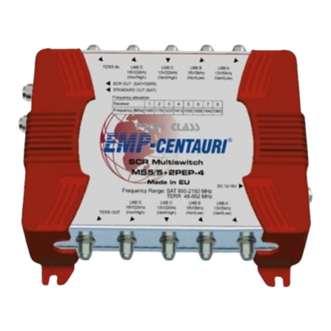
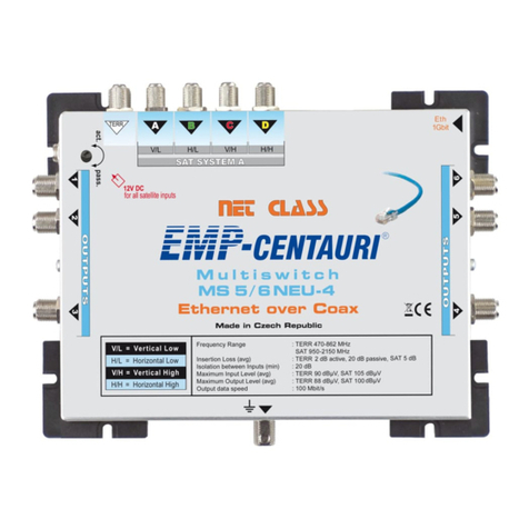
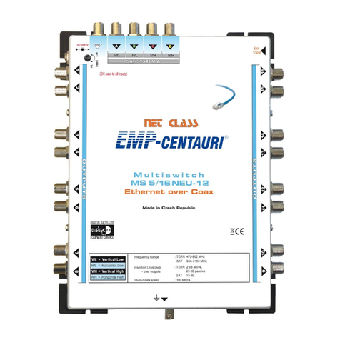
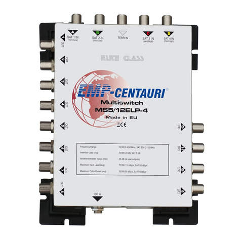
case of the Twin or Dual converter, or with the output of Horizontal Low in case of the Quatro
converter.
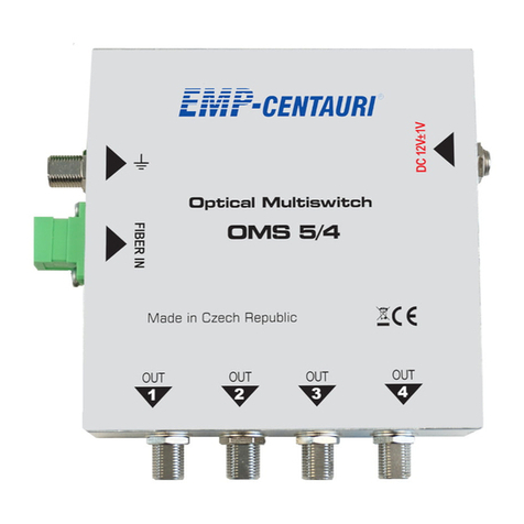
Connect the input marked 13 V / 22 kHz (LNB C) with the output of Vertical converter in case
of the Twin or Dual converter, or with the output of Vertical High in case of the Quatro converter.
Connect the input marked 18 V / 22 kHz (LNB D) with the output of Horizontal converter in
case of the Twin or Dual converter, or with the output of Horizontal High in case of the Quatro
converter.
Connect the input marked 13 V / 0 kHz (LNB E) with the output of Vertical converter in case of
the Twin or Dual converter, or with the output of Vertical Low in case of the Quatro converter.
Connect the input marked 18 V / 0 kHz (LNB F) with the output of Horizontal converter in
case of the Twin or Dual converter, or with the output of Horizontal Low in case of the Quatro
converter.
Connect the input marked 13 V / 22 kHz (LNB G) with the output of Vertical converter in case
of the Twin or Dual converter, or with the output of Vertical High in case of the Quatro converter.
Connect the input marked 18 V / 22 kHz (LNB H) with the output of Horizontal converter in
case of the Twin or Dual converter, or with the output of Horizontal High in case of the Quatro
converter.
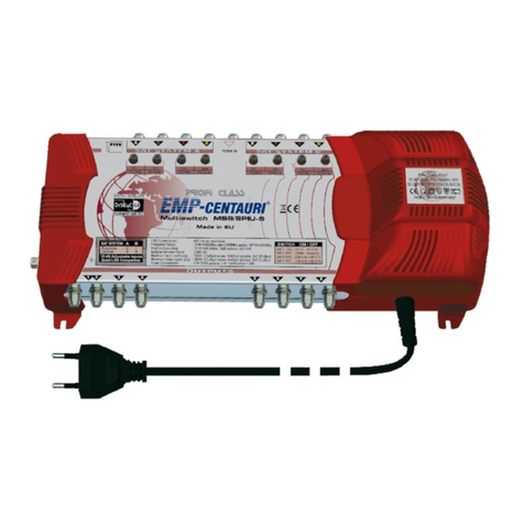
Also Quad-type converters can be used (with an integrated multiswitch) or Twin Universal for
reception of the High Band. The multiswitch is provided with four miniature lever switches situated
close to the multiswitch output connectors. If the switch 3 is in the OFF position the multiswitch
continually transmits to LNB inputs C and D a signal of 22 kHz which switches the corresponding
LNB outputs to the High Band. If the switch 4 is in the OFF position the multiswitch continually
transmits to LNC inputs G and H a signal of 22 kHz which switches the corresponding LNB out-
puts to the High Band. Further the multiswitch transmits 13 V DC to LNB inputs A, C, E, G and
18 V DC to LNB inputs B, D, F, H.
The Quad converter then operates as Quatro converter and the Twin Universal converter operates
as Dual converter for High Band reception. Switching between the satellite system A, i.e. the four
LNB inputs A through D, and the satellite system B, i.e. the four LNB inputs E through H, is pos-
sible with commands DiSEqC Position A and B from the satellite receiver.
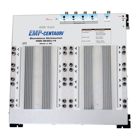
Connect the multiswitch input marked TERR. ANTENNA IN with the antenna output for reception
of terrestrial TV and radio. This input additionally enables to power supply the antenna pre-ampli-
er with the current up to 100mA / 12 VDC. Provided the current consumed by the pre-amplier
exceeds 100 mA an internal fuse disconnects the power supply of the pre-amplier. The antenna
may be also connected directly to the Terr. Antenna multiswitch input; in this case the power sup-
ply voltage is short-circuited and disconnected at the multiswitch input, however the signal quality
for terrestrial TV and radio is not affected.
The attenuation controller at the TERR. ANTENNA input may regulate the level of signals from the
terrestrial TV and radio antenna or from the pre-amplier. If the mini switch 1 is in the OFF posi-
tion, the internal amplier of the terrestrial TV and radio is switched off and the multiswitch oper-
ates as a passive hub for terrestrial TV and radio. In this case the multiswitch is able to transmit
the so-called reverse channel.
All satellite multiswitch inputs are provided with attenuation controllers which provide the option
to equalize signals of various strength at the inputs. This, however, requires adequate measuring
instruments.
The output connectors of the multiswitch are identied with OUT symbols. Run cables from the
multiswitch outputs into terminal subscriber outlets or hubs for satellite and terrestrial signals. If
the TERR. ANTENNA input is not connected, the cables from outputs may run directly into satel-
lite receivers.
We recommend impedance adjustment of unused outputs (OUT) or TERR. ANTENNA input by
screwing on terminators. Never connect the load to the satellite inputs!
•
•
•
•
•
•
4


