Inshore 380N User manual

Date: November 2016
Issue No: 2
Crewsaver - Servicing Manual : Inshore 380N Lifejacket
Page
of 31
1
R29965
SERVICE MANUAL
INSHORE 380N
LIFEJACKET
Survitec House, Lederle Lane, Gosport,
Hants. PO13 0FZ, England.
Tel: +44 (0) 1329 820000 Fax: +44 (0) 1329 236218
email: crewsa[email protected]
Web: www.crewsaver.com
1
R29965

Date: November 2016
Issue No: 2
Crewsaver - Servicing Manual : Inshore 380N Lifejacket
Page
of 31
2
No.
Issue 2
Description
Reference to Venturi Vacuum System
added (sections 6.1.2, 8.1.2 and Parts List)
Cylinder now has Netlon sleeve fitted (section 8.1)
Back pressure testing of the operating head added
Date
November 2016
Service Bulletins and Amendments Register

Date: November 2016
Issue No: 2
Crewsaver - Servicing Manual : Inshore 380N Lifejacket
Page
of 31
3
Index
Section 1
1.1 Introduction
1.2 Product Description
1.3 Data Sheet
1.4 General Features
1.5 Donning Instructions
Section 2
2.1 Service Station Guidelines
2.2 On Receipt Inspection
2.3 General Care
2.4 Servicing Tools
2.5 Service Record Sheet
2.6 Servicing Tool Kit
Section 3
3.1 Unpacking the Lifejacket
Section 4
4.1 Cleaning & laundering
Section 5
5.1 Inspection
Section 6
6.1 Testing
Section 7
7.1 Repairs
Section 8
8.1 Assembly
8.2 Packing instructions
Section 9
9.1 Replacement parts
Scope
This manual covers the servicing of the Inshore 380N lifejacket without any current
derivatives.

Date: November 2016
Issue No: 2
Crewsaver - Servicing Manual : Inshore 380N Lifejacket
Page
of 31
4
1.1 Introduction
1.2 Product Description
1.1.1. This Service Manual will be published on the Crewsaver website (www.crewsaver.com). Click on PARTNER
AREA/LOGIN at the top of the screen. Personnel who have been trained in the servicing procedures for this
lifejacket will be issued with a Username and Password to enable them to access the download section.
Each manual carries an Issue Number and records of issue are logged by Crewsaver to ensure that the
service network maintains correct and up to date servicing information. Emails will be sent regarding any
new Issues. Periodically service bulletins may be issued which will be published on the Crewsaver website
(www.crewsaver.com). Emails will also be sent. It is the service station's responsibility to regularly check the
website for any new bulletins and to ensure inclusion within the servicing manual. The service bulletin
register at the front of the Manual should be completed.
1.1.2. The information referenced in each section, follows a standard servicing procedure by which the inspection
should take place.
1.1.3. This servicing manual details information to enable regular maintenance and servicing of the lifejacket to
help prolong the life of the product and ensure it functions correctly.
1.1.4. The manual should be used as a reference document following training in servicing procedures instructed by
Crewsaver approved personnel. The manual also details the equipment and parts needed for correct
maintenance to be performed.
1.1.5. Servicing must be carried out annually at a service station authorised by the manufacturer.
1.1.6. Regular servicing is to be carried out by qualified personnel trained by Crewsaver and holding a valid
servicing certificate. Certificates are valid for a period of 3 years.
1 yr
1.2.1. The Inshore 380N is a single chamber Level 275 PFD (Inflatable lifejacket), designed, tested and developed
in collaboration with the RNLI, ensuring it is suitable for rescue boat crews of inshore lifeboats or advanced
powerboat users.
1.2.2. The lifejacket is CE approved to BS EN ISO 12402-2.
1.2.3. The lifejacket is easy to don.
1.2.4. The lifejacket has 90N of inherent buoyancy provided by closed cell foam. In addition a further 290N of
buoyancy can be achieved by means of a single chamber inflated by CO . The chamber is fitted with an oral
2
tube to ensure that full buoyancy can be achieved upon or after inflation.
1.2.5. The lifejacket is inflated by a HR manual operating head fitted with a 60 gr. CO cylinder.
2
1.2.6. This lifejacket is fitted with an integral deck safety harness with a 2-hook safety line, a spray hood and a
water activated light. The lifejacket has a YKK QBR Zip closure system.
1.2.7 The outer cover is made from a hard wearing material.
1.2.8 This lifejacket has permanently fitted dual crutch straps and dual lifting beckets.
1
Section

Date: November 2016
Issue No: 2
Crewsaver - Servicing Manual : Inshore 380N Lifejacket
Page
of 31
5
1.3.1 Data Sheet
Features:
Inflatable Buoyancy
Inherent Buoyancy
Total Buoyancy
Buoyancy Category
Cover Colour
MCA (UK) Approved
SOLAS Approved
CE Approved
Cylinder size
Standard Automatic
Hammar Automatic
Manual Firing head
Manual Override
Oral inflation tube
Hard wearing cover
Whistle - fitted
Retro-reflective tape
Twin Lifting Becket - fitted
Light - fitted
Spray Hood - fitted
Dual Thigh straps - fitted
Integral Deck Safety Harness
Closure method
Inshore 380N Lifejacket
290N
90N
380N
275N
Red
-
-
X
60g
-
-
X
-
X
X
X
X
X
X
X
X
X
YKK QBR Zip
1
Section

Date: November 2016
Issue No: 2
Crewsaver - Servicing Manual : Inshore 380N Lifejacket
Page
of 31
6
1
Section
1.4.1 General Features - Inshore 380N
Centre buckle, D ring and Harness
2 hooks and harness
Flare pocket
Manual toggle
SS40 buckles to
Secure crutch straps
Stretcher loops
3 burst QBZ ykk zip
Cover has been ergonomically designed to
Create supreme shape and fit. Allows user full
and unobstructed Movement.
Approved to BS EN ISO12402-2
Neck padding to prevent lifejacket rubbing at back of neck.
One size fits all.
Foam padded for maximum comfort.
Velcro webbing end tidies for neat finish.
Side pocket
Centre zip
SPRAY HOOD
WHISTLE
SINGLE CHAMBER
290N BLADDER
8 PIECES REFLECTIVE TAPE
HR MANUAL OPERATING HEAD,
60 gm CYLINDER LOCATED AT
BACK
40mm CRUTCH STRAP
WEBBING WITH VELCRO
WEBBING TIDY
CREWSAVER WATER ACTIVATED LIGHT
TWIN LIFTING BECKETS
MOUTH INFLATION TUBE
FRONT OF CHAMBER
(TO DEFLATE THE CHAMBER
INVERT THE TUBE CAP)

Date: November 2016
Issue No: 2
Crewsaver - Servicing Manual : Inshore 380N Lifejacket
Page
of 31
7
1.5.1 Donning Instructions - Inshore 380N
Section
1
Fasten centre buckle.
LLOYDS REGISTER
APPROVED,
AUTHORISED BY MCA
ADULT
43+KG
0191/#
Pull straps forward to
a tight but comfortable
tension.
Tighten straps to a tight
but comfortable tension.
Don life jacket like a waist coat Close centre zip
Fold excess waist webbing
into side slots. Pull lanyard to inflate lifejacket
Ensure crutch straps are fitted at all times
Fold excess webbing into
Velcro webbing tidy.

Date: November 2016
Issue No: 2
Crewsaver - Servicing Manual : Inshore 380N Lifejacket
Page
of 31
8
2.1.1 Service stations shall comply with the following as a minimum;
2.1.1.1 Servicing of Inflatable Lifejackets shall be carried out in a fully enclosed area only.
2.1.1.2 The area shall be well lit and protected from direct sunlight
2.1.1.3 The temperature and humidity shall be sufficiently controlled to ensure that the servicing of inflatable
Lifejackets may be carried out successfully.
2.1.1.4 The area shall be efficiently ventilated but free from draught
2.1.1.5 Sufficient tools (including specialist tools) shall be available to ensure Lifejackets may be
disassembled, tested and reassembled in accordance with this Manual. These shall include but not
limited to:
2.1.1.5.1 Manometers and pressure gauges
2.1.1.5.2 Oil free and dry air supply
2.1.1.5.3 Scales for weighing Gas Cylinders
2.1.1.5.4 Crewsaver Service tool kit (See 2.6). This is recommended but similar calibrated devices
may also be used.
2.1.1.6 Stock of materials and components to allow efficient servicing with readily available replacement parts
to ensure a prompt service for the customer.
2.1.1.7 Only personnel trained and certified in accordance with Crewsaver requirements are approved to
carry out Servicing and Maintenance. They must be holders of a valid Certificate issued by
Crewsaver.
2.1.1.8 The service station shall be of an approved standard.
2.1.1.9 Procedures shall be introduced to ensure that service bulletins, Manuals and replacement parts are
obtained from Crewsaver.
2.1.1.10 Subsequent to initial approval and thereafter the service station shall be subject to regular surveillance
by Crewsaver.
2.1.1.11 The service station must comply and have met all QA criteria in the Crewsaver servicing protocol file.
2.2.1 On receipt of the Lifejacket(s), check the state of the packaging before opening and notify the owner
and the company delivering the package of any defects or damage.
2.2.2 On opening the package, check the contents for their general condition and quantity.
2.2.3 Prepare Servicing Record Sheet.
2.2.4 Visually inspect the cover and inflation chamber for damage, abrasion, contamination etc. in
accordance with this manual.
2.2.5 Note replacements required on the record sheet.
2.2.6 Unless obvious damage is evident, test the Lifejacket in accordance with Section 6. If it is considered
that the damage found would cause the Lifejacket to fail the tests then corrective action shall be carried
out prior to testing.
2.2.7 Damaged areas shall be marked using wax based crayon only. Marks shall be made with a small circle
or
cross. Ballpoint, rollerball or other forms of ink shall not be used. If in doubt refer to Crewsaver for
guidance.
2.2.8 Repairs to the outer cover and the webbing are not permitted.
2.2.9 Repairs to welded components including the inflation chamber are expressly forbidden.
2.1 Service Stations
2.2 On Receipt Inspection
2
Section

Date: November 2016
Issue No: 2
Crewsaver - Servicing Manual : Inshore 380N Lifejacket
Page
of 31
9
2.3.1 The Lifejacket should be stowed in accordance with the manufacturer’s instructions
2.3.1.1 Lifejackets should be stowed in a dry compartment. Avoid high humidity, such as a car boot.
2.3.1.2 Lifejackets should have stowage facilities which are provided with a method to encourage
moisture removal.
2.3.1.3 Lifejackets should be stowed vertically, for example hung on hooks, in order that any trapped water
or condensation can drain away naturally.
2.3.1.4 Lifejackets should be rinsed in fresh water and dried thoroughly after use.
WARNING
Prior to sponging or washing remove automatic capsules from the firing mechanism. Allow to dry thoroughly
afterwards.
2.3.2 Contaminants such as oil or diesel fuel may be sponged off immediately with clean water and allowed
to dry naturally.
2.3.3 Mud can be removed with a stiff (not wire) brush when dry.
o
2.3.4 The outer cover may be hand washed in good quality mild detergent in cool water (40 C). Rinse well,
drip dry naturally in air.
2.3.5 Sponge the inflation chamber with pure soap solution only. Rinse in clean water immediately, inflate
and allow to dry naturally in air.
WARNING
Do not use proprietary cleaning fluids, thinners, spirits or similar substances.
2.3.6 In cases of severe contamination the unit shall be deemed beyond economic repair and the customer
advised to purchase a replacement lifejacket.
WARNING
Make sure you know how to use and fit this Lifejacket before an emergency occurs.
Always try and inflate the Lifejacket in the water. If already inflated, cross arms over the chest before jumping.
2.3.7 It is advised that personnel are familiarised with the operation of all Lifejackets and lifesaving
appliances.
2.3 General Care
2
Section

Date: November 2016
Issue No: 2
Crewsaver - Servicing Manual : Inshore 380N Lifejacket
Page
of 31
10
2.4 Lifejacket Servicing Tools
2.5 Lifejacket Service Record Sheet
2.5.1. An electronic copy of the sheet is available to aid reproduction (or copy next page).
2.5.2. Each lifejacket serviced should be recorded either individually or as a batch, showing the serial
numbers and the work performed during the service.
2.5.3. The service record sheet should be signed and a copy given to the owner certifying that the
lifejacket has been serviced.
2.5.4. All replacement parts should be noted - recording either the serial numbers of the component or
the expiry date.
2.5.5 The record sheet shown on the next page is a recommended version. Similar record sheets,
including the same information, may also be used.
2
Section
Fig. 2.4 Table of Tools Required
Crewsaver Servicing Tool Kit
A fine screw driver or tool suitable for removing gaskets
Boning tool
Roller
Brushes
Scissors or good quality trimming shears
“Chinagraph” pencil
Tailors chalk
Fine point indelible pen
1 off metal calibrated metre stick
Scales to weigh gas cylinders 0-1000gram (+1/-1 grams)
Adaptor/tee piece for testing inflation chambers.
Manometer 0-500Mbar
Timing Device
Thermometer 0-40ºC
Clean and dry air supply
1 off ball pein hammer
450mm wide bag sealer (3mm element)
Crewsaver Venturi Vacuum System
Back pressure test unit
Suitable large surface area for the work to be carried out
Description Type

Date: November 2016
Issue No: 2
Crewsaver - Servicing Manual : Inshore 380N Lifejacket
Page
of 31
11
2
Section 2
LIFEJACKET SERVICING SCHEDULE
SERVICED BY:
CERTIFICATE NUMBER:
VESSEL
W/O Number:
LAST SERVICED BY DATE OF LAST SERVICE
SERIAL NUMBER/S:
RQ
CHAMBER INSPECTION COMMENTS
GENERAL CONDITION
MATERIAL
WELDS
WEBBINGS
RETRO TAPE
WHISTLE
ORAL TUBES
RELIEF VALVES
MANIFOLDS
Schrader VALVES
CYLINDERS
LIGHT
CYALUME POCKET
BUDDY LINE
RQ
INFLATION MECHANISM COMMENTS
OPERATING
MECHANISM
CORD
AUTOMATIC CAPSULE
WASHERS
RETAINING NUT
RETAINING CLIP
TOGGLE
RQ
SPRAY HOOD COMMENTS
FABRIC
ATTACHMENT
VELCRO
REPAIRED ITEMS (COMMENTS)
TYPE
CUSTOMER
RQ
WEBBINGS COMMENTS
WAIST BELT / HARNESS
BACK STRAP
LIFTING BECKET
CROTCH STRAP
BUCKLES
STITCHING
ON
OFF
RELIEF VALVE TEST RESULTS FRONT
CHAMBER
OPEN
CLOSE
REAR
CHAMBER
DATE:
RQ
COVER COMMENTS
MATERIAL
VELCRO
ZIP
PLB POCKETS
PRESSURE TEST RESULTS
FRONT
CHAMBER
REAR
CHAMBER
TIME
TEMP. ON OFF
R29965R29965

Date: November 2016
Issue No: 2
Crewsaver - Servicing Manual : Inshore 380N Lifejacket
Page
of 31
12
2
Section 2
2.6 Lifejacket Servicing Tool Kit
Cylinder Torque Strap
UML Mk5 Auto Socket
Manometer
Valve Extraction Tool
Pressure Measuring
Adaptor
Inflation Adaptor
Turned Socket
Calibrated Socket Driver
(Tighten Cylinder)
Calibrated Socket Driver
(Remove & Replace Locking
Nuts For UML & HR)
Calibrated Torque Driver
(Schraeder Valve)
Date: November 2016
Issue No: 2
Crewsaver - Servicing Manual : Inshore 380N Lifejacket
Page
of 31
13
3.1 Unpacking the Inshore 380N
WARNING: All defects should be noted onto the service record sheet.
3.1.2 Following unpacking refer to:
a.) Manual Operation: Fig 3.2 - Halkey Roberts operating head removal.
3.1.2.1.2 Carefully remove the inflation cylinder by unscrewing it from the operating
mechanism. Retain for further Inspection. Refer to Section 5.
3.1.2.1.3 Remove Operating Mechanisms (and upper and lower manifold gaskets) by
unscrewing the retaining nut on the top of the inflation mechanism. Retain for further
Inspection. Refer to Section 5.
3.1.3. Remove light and battery. Place to one side for further inspection. Refer to section 5.
3.1.4 Remove Safety Line and place to one side for further inspection. Refer to Section 5.
3.1.5. For Cleaning. Refer to Section 4.
3.1.6. Carry out visual inspection. Refer to section 5.
3
Section
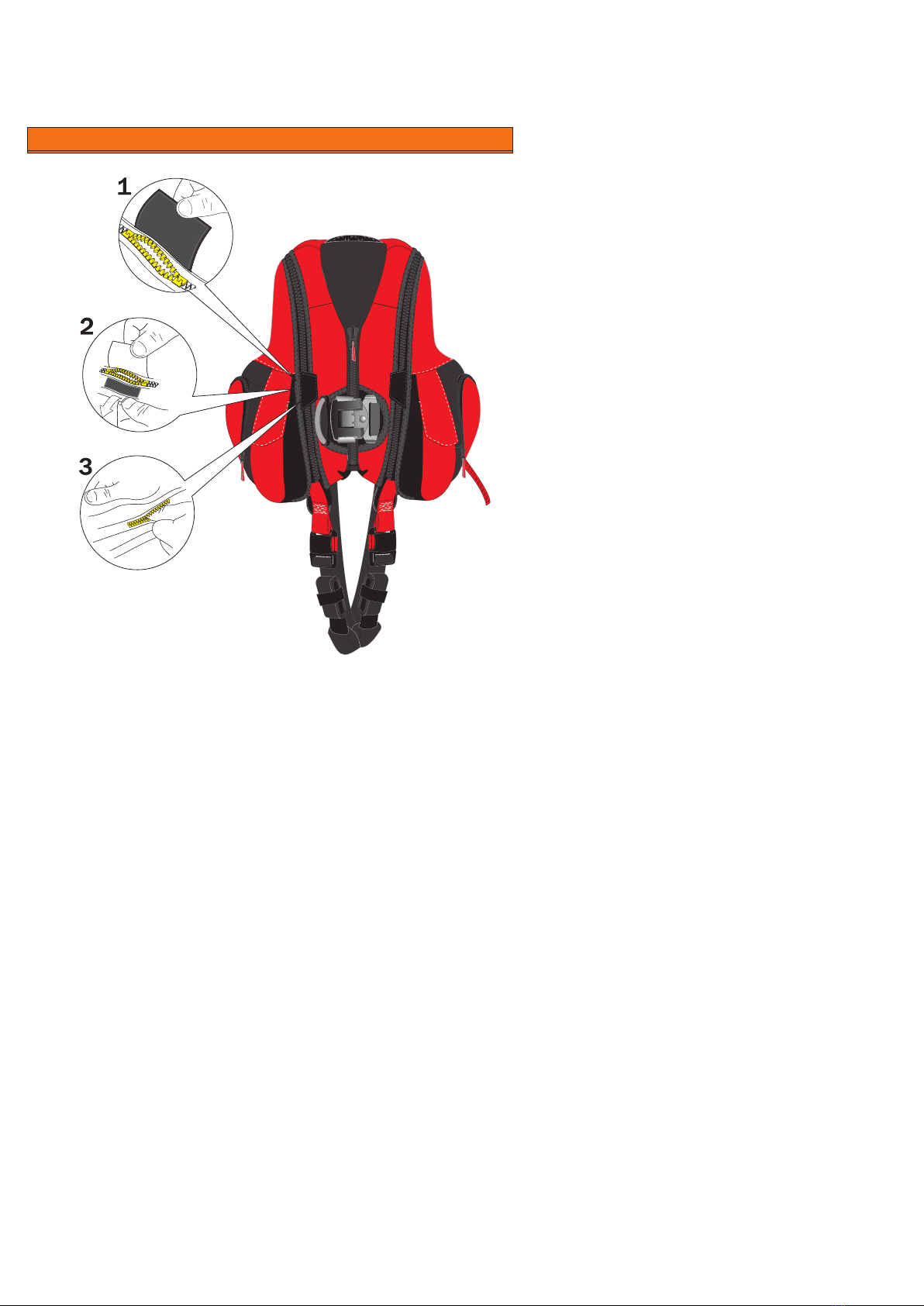
OPENING THE LIFEJACKET COVER
1. Open the velcro tab.
2. Pull apart the zip, opening the zip via
the 3 quick burst elements, holding the
cover either side.
3. Once the zip has opened insert your
finger and slide it around the Lifejacket.
Undo the zip all the way around the
outside of the lifejacket. The Lifejacket
cover should now be open and the
inflation chamber visible.
Fully separate the zip. Both sides of the
zip should be apart, with the zip slider
free to move back around the lifejacket
to the start.
Date: November 2016
Issue No: 2
Crewsaver - Servicing Manual : Inshore 380N Lifejacket
Page
of 31
14
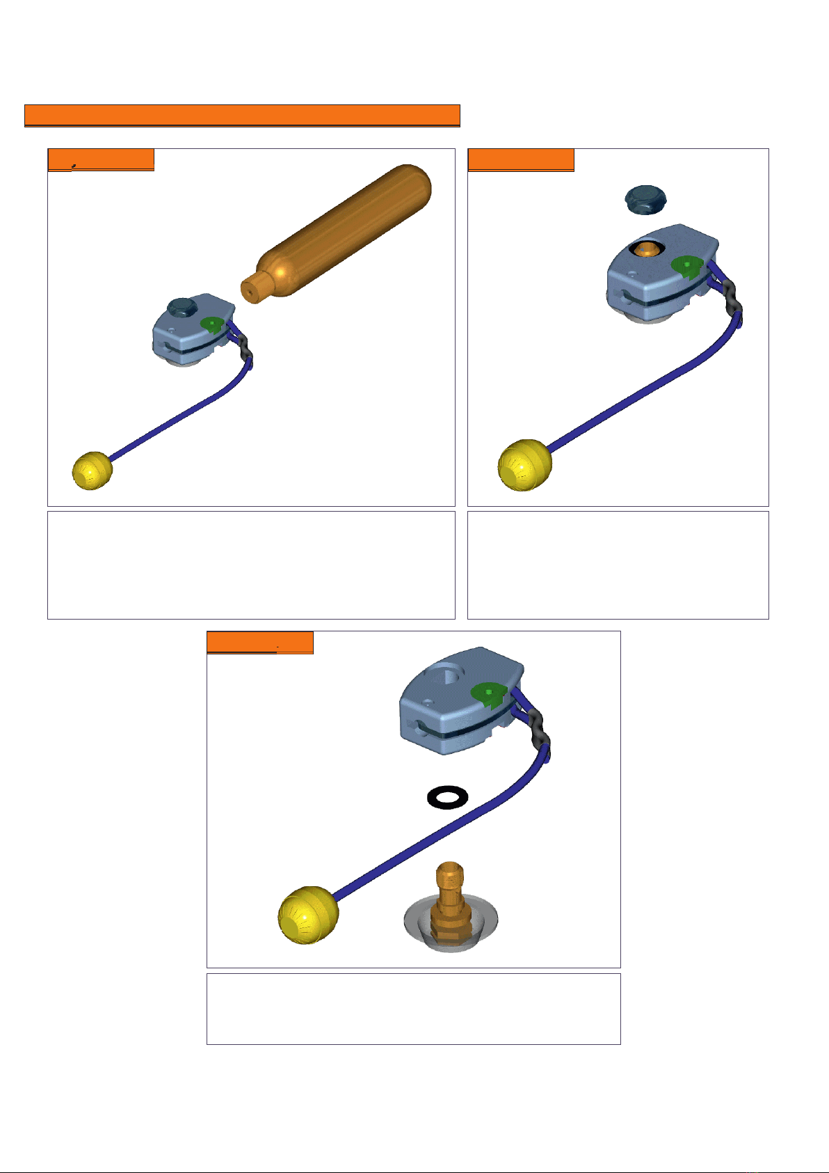
Fig. 3.2.2Fig. 3.2.1
Unscrew the 60 gram cylinder from the manual firing head. Check
to see if the cylinder has been used.
NOTE: This should be performed by check weighing. If under the
min. weight as displayed on the cylinder body, discard in a safe
manner.
Unscrew the valve retaining nut from the top of
the firing head, using a 9/16” socket or spanner.
Check for corrosion, discard if corroded.
Remove the top sealing gasket/ washer and
discard. This must be replaced with a new part
upon reassembly.
Fig 3.2 Halkey Roberts Operating Head
Fig. 3.2.3
Remove the operating head from the manifold which is welded to
the inflator fabric. Remove the bottom gasket / sealing washer and
discard. This must be replaced with a new part upon reassembly.
Please Note: The operating head may not match the images above, but the processes are always the same.
Section
3

Date: November 2016
Issue No: 2
Crewsaver - Servicing Manual : Inshore 380N Lifejacket
Page
of 31
15
4.1 Cleaning Lifejackets
4.1.1 The current standard cover of the Inshore 380N is made from a polyester fabric with a polyurethane
coating that can be cleaned with care. In the event that contamination is such that the materials are
inherently damaged refer to section 7.
4.1.2 For all types of cover, mud can be removed with clean water and the zip can be cleaned with a stiff (not
wire) brush when dry.
4.1.2.1 Contaminants such as oil or diesel fuel may be sponged off immediately with clean water and
allowed to dry naturally.
4.1.2.2 Mud can be removed with a stiff (not wire) brush when dry.
4.1.2.3 Covers may be hand washed in good quality mild detergent in cool water (40°C). Rinse well,
air drip dry.
4.1.3 Sponge the inflation chamber with PURE SOAP SOLUTION ONLY. Rinse in clean water immediately,
inflate and air dry.
WARNING: Do not use proprietary cleaning fluids, thinners, spirits or similar substances.
4
Section
Date: November 2016
Issue No: 2
Crewsaver - Servicing Manual : Inshore 380N Lifejacket
Page
of 31
16
5.1.1 Visually inspect the cover material for wear, abrasion, pulled threads, contamination, cuts and holes.
5.1.2 If necessary the cover may be washed. Refer to Section 4.
5.1.3 Repairs to the outer cover are not permitted.
5.1.4 Carefully examine the zips and the slider for wear, broken teeth or slider and worn or fraying tape.
5.1.5 If it is considered that the cover is so badly damaged that the lifejacket is no longer serviceable, the
customer shall be advised and offered a replacement lifejacket.
NOTE: Due to the construction of this lifejacket no individual cover is available for replacement, therefore
the lifejacket as a whole must be replaced.
5.2.1 Visually inspect the inflation chamber material for wear, pulled threads, contamination or signs of
mistreatment .
5.2.2 Visually inspect all welds.
5.2.3 Visually inspect all webbings in accordance with Section 5.8
5.2.4 Visually inspect the whistle and its attachment to the lifejacket for mistreatment, defects, and fraying of
the cord and its attachment.
5.2.5 Test Lifejacket in accordance with Section 6.
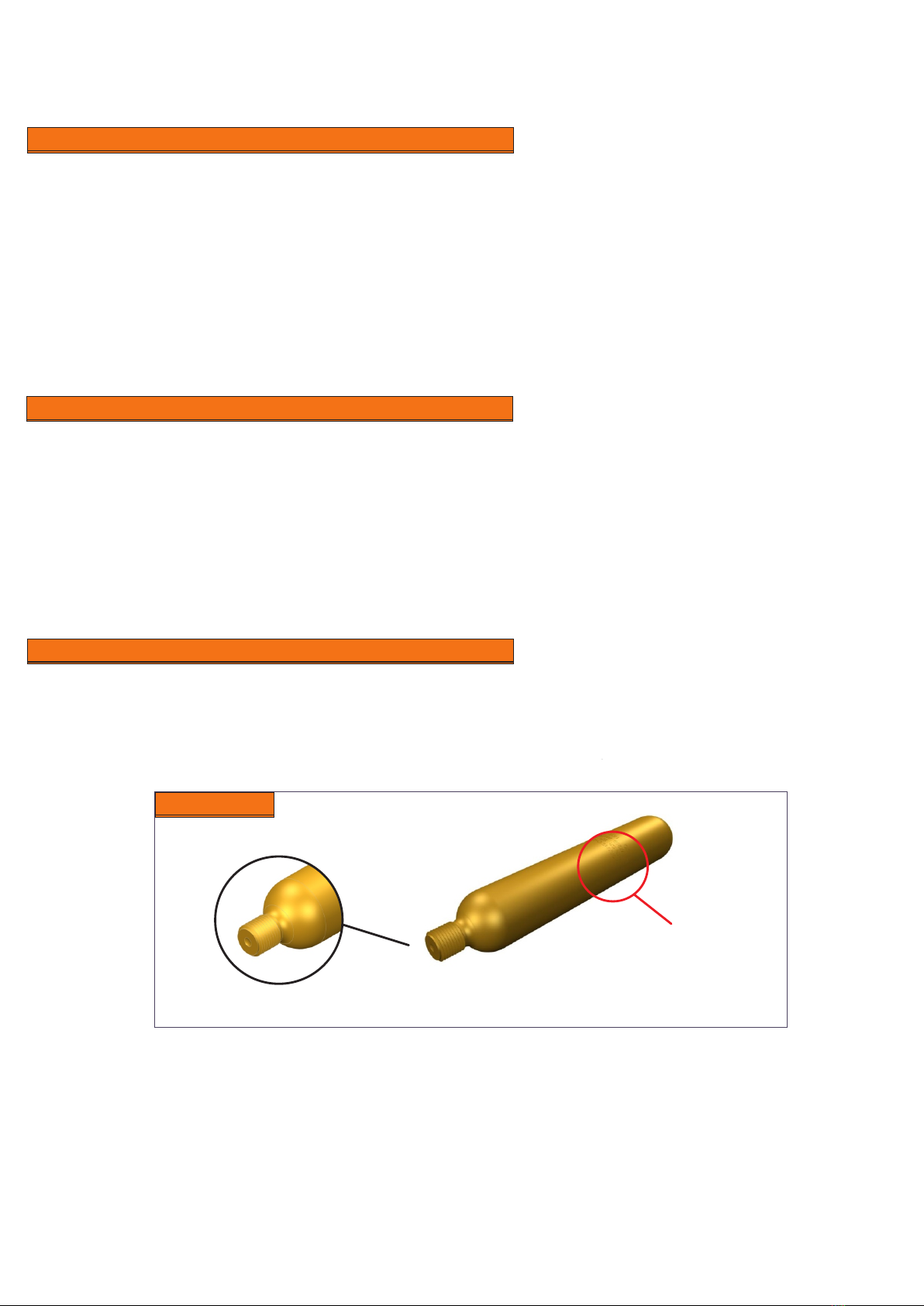
5.3.1 Visually examine:
5.3.1.1. For Corrosion in accordance with the procedure detailed overleaf. (All cylinders corroded with
red rust or with visible pitting must be replaced).
5.3.1.2. Pierced or damaged piercing disc.
5.3.1.3. That the cylinder has the correct gas charge - 60 grams CO2
5.3.2 Check Min Weight of Cylinder against that marked on the barrel.
Remedial Action: If any of the above conditions are found to be incorrect the cylinder shall be replaced. See
Section 9.
5.1 Outer Cover Inspection
5.2 Inflation Chamber Inspection
5
Section
5.3 Gas Cylinders
60 GRAMS CO2 NOMINAL
MIN GR. WT. 245.16G
ISI/38200 AUSTRIA 07/08
DO NOT HEAT
Fig. 5.3
Date: November 2016
Issue No: 2
Crewsaver - Servicing Manual : Inshore 380N Lifejacket
Page
of 31
17
5
Section
PROCEDURE FOR THE INSPECTION AND SERVICING OF MANUAL HEADS AND CYLINDERS WITH LEVELS OF
CORROSION
5.3.3 INITIAL INSPECTION
Unscrew the cylinder from the automatic or manual head. If corrosion is present it will be seen as one of the following:
a) A white/grey powdery deposit on the cylinder and in the thread recess of the head.
b) A red rusty surface to the cylinder.
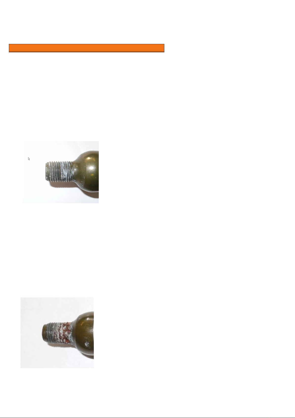
5.3.4 PROCEDURE FOR WHITE/GREY POWDERY DEPOSIT
5.3.4.1 All CO cylinders showing signs of white rust and no pitting are
2
considered fit for purpose. If the white/grey deposit is seen then both the
cylinder and head can be reused after cleaning. Brush out the threads
with a stiff bristled nylon brush (M.E.C. Reference Br1)
Cylinder showing white rust on thread
5.3.4.2 Blow out the threaded recess of the head and check that there are no significant particles or bristles from the brush
across the sealing washer in the base of the recess. Check that the sealing washer is not damaged, either from
cleaning or use, and will provide a good seal. Replace if damaged.
5.3.4.3 Check that the head operates freely.
5.3.4.4 If any white/grey powdery deposit is present on the body of the cylinder within the areas shown in Section 4 then it
should be brushed or wiped off.
5.3.4.5 Re-assemble the cylinder to the manual or auto head.
5.3.5 PROCEDURE FOR RED RUSTY SURFACE
Cylinder showing red rust
5.3.5.1 If a red rusty surface is seen on the cylinder this means that the protective
zinc coating has been penetrated and the steel is corroding.
5.3 Gas Cylinders (cont.)

Date: November 2016
Issue No: 2
Crewsaver - Servicing Manual : Inshore 380N Lifejacket
Page
of 31
18
5
Section
5.3.6. PROCEDURE FOR ZINC/SUPER ZINC COATING
2
5.3.6.1 All CO cylinders showing signs of wear and loss of Zinc/Super Zinc coating larger than 1cm are considered unfit
2
for purpose.
2
Acceptable wear - less than 1cm
2
Acceptable wear - less than 1cm
Not acceptable wear - Reject. DO NOT USE
Not acceptable wear - Reject. DO NOT USE
5.3 Gas Cylinders (cont.)

Date: November 2016
Issue No: 2
Crewsaver - Servicing Manual : Inshore 380N Lifejacket
Page
of 31
19
5.4.1 Visually inspect for damage.
5.4.2 Test in accordance with Section 6.
Remedial Action: These items are not repairable. Refer to Section 9 for replacement part.
5.5.1 Visually inspect the Operation of the Manual Mechanism for:
5.5.1.1 Operation of the Manual lever. This shall move easily and freely.
5.5.1.2 Operation of the firing pin cam action. Similarly this shall be a smooth action when
the lever is operated.
5.5.1.3 Firing Pin centre discharge hole clear.
5.5.1.4 Activation cord for frays and damage.
5.5.1.5 Moulded body for cracks and damage. Special attention to be given to the areas
around the operating lever/body connection pin.
Remedial Action: In the event that the Operating Mechanism fails any of the above inspection procedures, the
complete unit shall be replaced. No Repairs are allowed. Refer to Section 9 for the part number of the relevant
replacement part.
5.4 Oral Valves
5
Section
5.5 Inflation System
5.6 Safety Line
5.6.1 Examine the Safety Line for any damage to the webbing or the stitching. If necessary remove any fluff from the
webbing. Check that there is no rust on the hooks. Check the operation of the self locking hooks and spray with
WD40 if necessary. Check that both of the hooks are facing the same way.
Remedial Action: No repairs are allowed. In the case of damage being found, return the Lifejacket to Crewsaver.
5.7.1 Remove the foam panels from the jacket by unfastening the velcro fastenings on the inside faces of the front
and back of the jacket. Check for any deterioration against the templates provided.
Remedial Action: No repairs are allowed. In the case of damage being found, return the Lifejacket to Crewsaver.
5.7 Foam Panels

Date: November 2016
Issue No: 2
Crewsaver - Servicing Manual : Inshore 380N Lifejacket
Page
of 31
20
5.8.1 Visually inspect for damage:
5.8.1.1. Fraying
5.8.1.2. Pulled Threads
5.8.1.3. Broken Stitches
Remedial Action: No repairs are allowed. In the case of damage being found, return the Lifejacket to Crewsaver.
5.9.1 Check that the single point release buckle latches and unlatches correctly. Check that the two
screws are flush with the surface and do not affect the latching operation of the buckle. DO NOT test
the tightness of the screws using a conventional screwdriver as this may cause the thread to strip in
the plastic saddle. If the tightness has to be checked it must be done with a torque screwdriver set to
15 lbf/in.
Remedial Action: No repairs are allowed. In the case of damage being found, return the Lifejacket to Crewsaver.
5.10.1 Check all Markings and Labelling are clear and legible.
Remedial Action: No repairs are allowed. In the case of damage being found, return the Lifejacket to Crewsaver.
5
Section
5.8 Webbings
5.9 Buckles
5.10 Labelling/Markings
5.11 Lights
R29965
5.11.1 This lifejacket is fitted with the Crewsaver CSL water activated light.
5.11.1.1 Check the expiry date of the light. Upon expiry the light should be removed by prising off
the plastic security clip. Take care not to damage the jacket. A new light should then be
fitted.
5.11.1.2 Inspect the light for any signs of damage. If there are chips or cracks the light must be
replaced.
5.11.1.3 Check that the light is securely attached to the lifejacket.
5.11.1.4 Ensure that the water activated switch is in the Auto-on position as shown below.
5.11.2 To test this unit to ensure the light is working correctly, immerse the water-activated switch in water.
The light should flash. Remove the light from the water and dry it. The light should stop flashing. If
the light does not flash when immersed in water the unit has expired and must be replaced.
5.10.3 These lights are not repairable; if the light fails inspection it must be replaced.
Expiry date
printed on end
Water activated switch in Auto-on
position (Earlier models)
Water activated switch in Auto-on
position (Later models)
Table of contents


