Inside Out Networks Digi Edgeport/2i User manual

Installation
Guide
Edgeport
U S B E X P A N S I O N M O D U L E S
IN D U S T R I A L

(This page intentionally left blank.)

Edgeport/2i
Edgeport/4i
Edgeport/8i
Installation
Guide
Table of Contents
Cabling the Edgeport/2i, 4i, and 8i ................................3
Configuring the DIP Switches........................................3
Installing Edgeport Drivers............................................4
Plugging Edgeport Into Your PC................................... 6
Appendix
A. Using USB with Windows 95.............................7
B. Using the Edgeport Utility Program.................. 9
C. Using the USB Status Utility (USB Viewer)....10
D. Interpreting the System Status Light.............. 10
E. USB Cabling Diagrams....................................10
F. Mounting Diagrams.......................................... 11

2 (This page intentionally left blank.)
Edgeport, Hubport, Rapidport, and Step Up Kit are a trademarks of Inside Out Networks. All other products are trade-
marks or registered trademarks of their respective owners.
Information in this documentation is subject to change without notice and does not represent a commitment on the part
of Inside Out Networks Inc.
Inside Out Networks provides this document “as is,” without warranty of any kind, either expressed or implied, including,
but not limited to, the particular purpose. Inside Out Networks may make improvements and/or changes to this docu-
mentation or to the product(s) and/or program(s) described in this documentation at any time.
Inside Out Networks assumes no responsibility of any errors, technical inaccuracies, or typographical errors that may
appear in this documentation, nor liability for any damages arising out of its use. Changes are made periodically to the
information herein; these changes may be incorporated in new editions of the publication.
For U.S. Government use:
Any provision of this document and associated computer programs to the U.S. Government is with “Restricted Rights.”
Use, duplication, or disclosure by the government is subject to the restrictions set forth in, subparagraph (c) (1) (ii) of the
Rights in Technical Data and Computer Software clause of DFARS 52.277-7013.
For non-U.S. Government use:
These programs are supplied under a license. They may be used, disclosed, and/or copied only as supplied under such
license agreement. Any copy must contain the above copyright notice and restricted rights notice. Use, copying, and/or
disclosure of the programs is strictly prohibited unless otherwise provided for in the license agreement.
Federal Communications Commission (FCC) Regulatory Information (USA only)
This equipment has been tested and found to comply with the limits for a Class B digital device, pursuant to Part 15 of
the FCC Rules. These limits are designed to provide reasonable protection against harmful interference in a residential
installation. This equipment generates, uses, and can radiate radio frequency energy and, if not installed and used in
accordance with the instructions, may cause harmful interference to radio communications. However, there is no guar-
antee that interference will not occur in a particular installation. If this equipment does cause harmful interference to
radio or television reception, which can be determined by turning the equipment off and on, the user is encouraged to
correct the interference by one or more of the following measures:
• Reorient or relocate the receiving antenna.
• Increase the separation between the equipment and the receiver.
• Connect the equipment into an outlet that is on a circuit different from the receiver.
• Consult the dealer or an experienced radio/TV technician for help.
Warning: The connection of a non-shielded interface cable to this equipment will invalidate the FCC Certification for this
device.
Department of Communication (DOC) Notice
(Canada only)
This Class B digital apparatus meets the requirements of
the Canadian Interference-Causing Equipment Regula-
tions.
Cet appareil numérique de la Classe B respecte toutes
les exigences du Règlement sur le matériel brouiller du
Canada.
European Community - CE Mark
Declaration of Conformity (DOC)
according to ISO/IEC Guide 22 and EN 45014
Manufacturer’s Name: Inside Out Networks
Manufacturer’s Addr.: 7004 Bee Caves Rd.
Bldg. 3, Suite 200
Austin, Texas 78746 USA
declares that the product
Product Name: Edgeport/2i, Edgeport/4i,
Edgeport/8i
Model Number(s): 301-1000-12, 301-1000-24,
301-1000-28
Product Options: All
conforms to the relevant EU Directives listed here:
EMC Directive 89/336/EEC |
Low Voltage Directive 73/23/EEC
Amending Directive 93/68 EEC
Using the relevant section of the following EU stan-
dards and other normative documents:
Safety:IEC 950:1991 +A1, A2, A3, A4
EN 60950:1992 + A1, A2, A3, A4
EMC: EN 55022 Class B (1994 w/A1 1995)
EN 50082-1:1992 - Immunity to Electromagnetic
Disturbance
IEC 801-2
IEC 801-3
IEC 801-4
FCC Regulation - Part 15
Declaration of Conformity (DoC)
This device complies with the requirements of the Code
of Federal Regulations listed below:
FCC Title 47 CFR, Part 15 Class B for a digital device.
Operation is subject to the following two conditions: 1.
this device may not cause harmful interference, and 2.
this device must accept any interference received, in-
cluding interference that may cause undesired operation.
UL/CSA Safety Information
This device complies with the requirements of following
safety standards below:
UL 1950, 3rd edition
CSA No. 950
Quality Manager, Austin, Texas July 2001
2
Edgeport/2i, 4i, and 8i
Cabling the Edgeport/2i, 4i, and 8i
Cable Connections (DB9 Female) for Full Duplex
3 !TA(T-) transmit data negative
7 !TB(T+) transmit data positive
8 !RA(R-) receive data negative
4 !RB(R+) receive data positive
5 !signal ground
1, 2, 6, 9 no connect
NOTE: For full duplex (in the above diagram) the differential pair TAand TBshould be to-
gether in one twisted pair and RAand RBshould be together in another twisted pair.
Cable Connections (DB9 Female) for Half Duplex
3 !TA(T-) transmit data negative
7 !TB(T+) transmit data positive
8 !RA(R-) receive data negative
4 !RB(R+) receive data positive
5 !signal ground
1, 2, 6, 9 no connect
NOTE: Half duplex contains only one twisted pair.
Configuring the DIP Switches
The Edgeport/8i does not have any DIP switches to configure for either Duplex or
Grounding. If you have an Edgeport/8i you may proceed to “Installing Edgeport Drivers”
on page 4.
2 Position Switch on Edgeport2/i and 4/i
Both the Edgeport/2i and Edgeport/4i have a two position DIP switch. This switch con-
nects the signal ground to chassis ground. IMPORTANT: Do not connect signal ground to
chassis ground on more than one location in order to prevent ground loops and potentially
high currents (figure 1).
After setting the two position DIP switch on the
Edgeport/4i (designed to give you four RS-422
serial ports), you may proceed to “Installing Edge-
port Drivers” on page 4. For the Edgeport/2i, con-
tinue with the next section.
1 2 3 4 5 6 7 8
"#
"#"#
"#ON $#
$#$#
$#OFF
1. echo disabled 1. echo enabled
2. half duplex 2. full duplex
3. terminating 3. no terminating
resistor resistor
4. ---------- 4. set to OFF
5. set to ON 5. ----------
6. set to ON 6. ----------
7. not used 7. not used
8. not used 8. not used
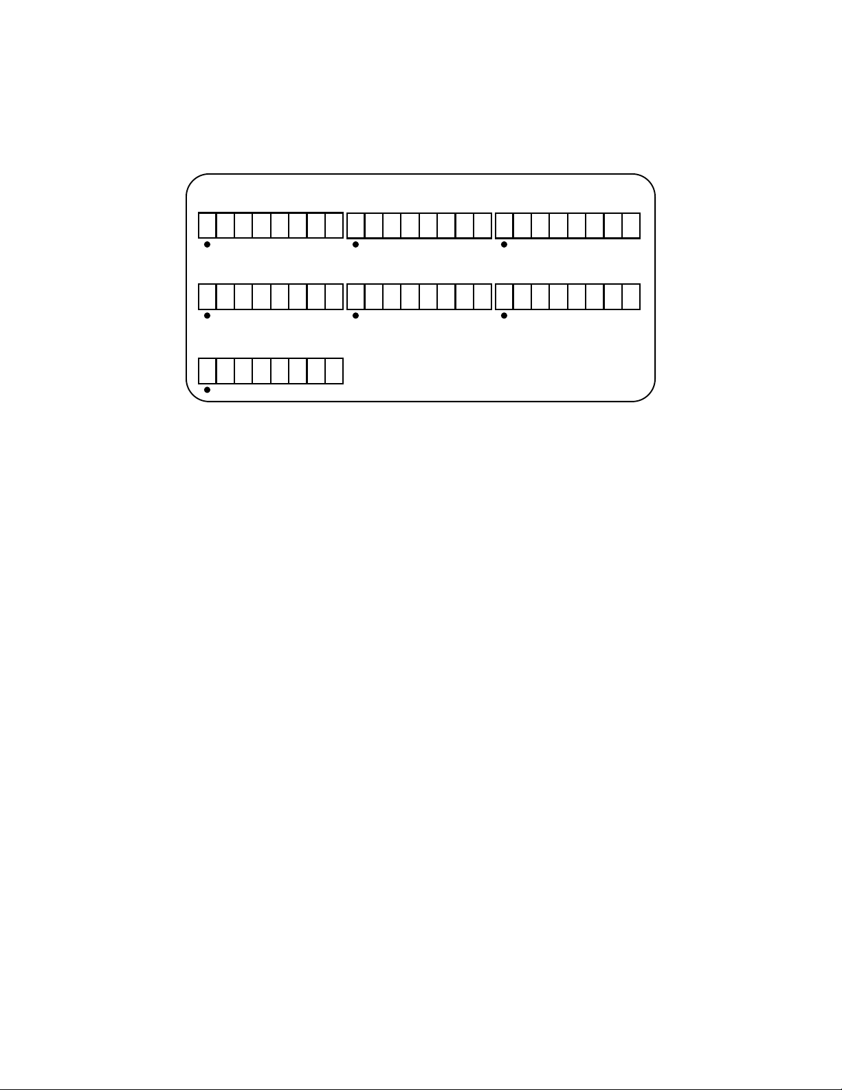
Figure 2: Eight Position DIP Switch
1 2
DS1: "ON signal ground short to chassis
ground
$OFF signal ground isolated from chassis
ground
DS2: not used
Figure 1: Two Position DIP Switch
3
8 Position Switch on the Edgeport/2i
The Edgeport/2i, which supports both RS-422 and RS-485, has two sets of eight position
DIP switches, one set for each serial port. Figure 2 shows what each switch selects in its
ON and OFF positions. Consult the diagrams in figure 3 for various configuration options.
For more configuration information, go to the documentation section of our web site at
www.ionetworks.com/support. After configuration, you may proceed to “Installing Edge-
port Drivers” on this page.
Installing Edgeport Drivers
The installation instructions in this guide are for installing the Edgeport software from CD.
If you are installing from diskette and using Windows 95 or 98, when prompted for the
location of the drivers, specify your 3-1/2” floppy drive (usually
a:
). NT users will not be
prompted and will need to locate the driver by double-clicking on their floppy drive. In ei-
ther case, you will not need to specify a directory.
These installation instructions are for installing the Edgeport software from CD. If you are
installing from diskette and using Windows 95, 98, CE, SE, ME, or 2000, when prompted
for the location of the drivers, specify your 3-1/2” floppy drive (usually a:). NT users will
not be prompted and will need to locate the driver by double-clicking on their floppy drive.
In either case, you will not need to specify a directory.
For Windows 95 Users
Follow the instructions described in "Plugging Edgeport Into Your PC" on page 6. After
connecting the USB cable, if the Update Device Driver Wizard dialog does not appear,
please review "Using USB with Windows 95" in the Appendix. Otherwise, click "Next" to
continue with driver installation.
To install the Edgeport drivers:
1) Insert the "Edgeport Driver" CD into your CD-ROM drive.
2) After Windows fails to locate the drivers on your floppy disk drive, click "Other
Locations...".
$
$$
$$
$$
$%$
$$
$"
""
""
""
"X X
Option #1: RS-422 to RS-422
%"
""
""
""
"$
$$
$"
""
""
""
"X X
Option #2: RS-485 Half Duplex
End Unit with Terminating Resistor
%"
""
"$
$$
$$
$$
$"
""
""
""
"X X
Option #3: RS-485 Half Duplex
Middle Unit
$
$$
$"
""
""
""
"$
$$
$"
""
""
""
"X X
Option #5: RS-485 Full Duplex
End Unit, Slave
$
$$
$$
$$
$$
$$
$$
$$
$"
""
""
""
"X X
Option #6: RS-485 Full Duplex
Middle Unit, Master
$
$$
$$
$$
$"
""
"$
$$
$"
""
""
""
"X X
Option #4: RS-485 Full Duplex
End Unit, Master
$
$$
$"
""
"$
$$
$$
$$
$"
""
""
""
"X X
Option #7: RS-485 Full Duplex
Middle Unit, Slave Key: "#on %#user’s chioce
$#off X doesn’t matter
Figure 3: Various Configurations for the Edgeport/2i DIP Switches
4

5
3) When the Select Other Location dialog appears, type <CD drive letter>:\Win95 and
click "OK".
4) Confirm that Windows has found the correct driver location and click "Finish".
5) When Windows prompts you for the driver disk, click "OK".
6) At the next Windows prompt, type <CD drive letter>:\Win95 and click "OK".
After installing the drivers, Windows will detect your Edgeport's new COM ports and will
begin to initialize them. Installation is complete when no more dialogs appear. Your new
communication ports, numbered sequentially following the existing ports in your system,
are now ready!
For Windows 98, CE, SE, and ME Users
1) Insert the "Edgeport Driver" CD into your CD-ROM drive.
2) Follow the instructions described in "Plugging Edgeport Into Your PC" on page 6.
After connecting the USB cable, the Add New Hardware Wizard appears. Click "Next".
3) Select "Search for the best driver for your device" and click "Next".
4) Select "Specify a location" and type in <CD drive letter>:\Win98. Then click "Next".
5) Confirm that Windows is pointing to <CD drive letter>:\Win98. Click "Next".
Windows will then copy over the driver files.
6) Click "Finish" to complete the driver installation.
After installing the drivers, Windows will detect your Edgeport's new COM ports and will
begin to initialize them. Installation is complete when no more dialogs appear. Your new
communication ports, numbered sequentially following the existing ports in your system,
are now ready!
For Windows NT Users
Because Microsoft does not support USB in NT4.0, Inside Out Networks supplies a USB
stack that will be installed along with the necessary drivers. NOTE: You must install the
drivers using an account that has administrative privileges!
To install the USB stack and Edgeport drivers:
1a) Insert the “Edgeport Driver” CD into your CD-ROM drive.
2a) When the welcome dialog appears, click the “Install Driver” button.
- OR -
1b) From the Start menu, select Run.
2b) Type <CD drive letter>:\NT40\ip4n4XXX.exe, and click “OK”.
Note: “XXX” represents a version number. Example: Driver version 1.31 would be
ip4n4131.exe.
Once the driver installation program has begun, follow the on screen instructions.
3a)
If you are installing drivers for the first time
: An Information dialog informs you that
the installation was successful. After clicking “OK”, the installation is complete.
3b)
If you are replacing version 1.14 or later:
Follow the on-screen instructions. Note
that before beginning the installation of the drivers, all applications with open ports
must be closed and all USB devices unplugged. If you close all the applications and
unplug all the USB devices, then you will not need to reboot for the new drivers to take

6
effect immediately. If any applications are left open or USB devices plugged in, you
may choose to abort the installation or to continue and be required to reboot before the
upgrade can take effect.
3c)
If you are replacing version 1.13 or earlier:
The Edgeport Drivers Installation
Complete dialog tells you that the Edgeport drivers have been updated. Before the
updates can take effect, however, you will need to reboot your computer. To reboot
immediately, eject the “Edgeport Driver” disk, select the option to restart the computer
now, and click “Finish”.
Plugging Edgeport Into Your PC
Plug the Type A end of the USB cable into the USB port located in the back of your PC
or into an available USB port on a standard hub or into an Inside Out Networks Hubport.
Plug the Type B end of the USB cable into the back of the Edgeport.*
If the drivers are not already installed, you may return to the installation instructions for
your operating system or proceed to the "Installing Edgeport Drivers" section, beginning
on page 4.

Appendix A
Using USB with Windows 95
If you are using Windows 95 OSR2.1 or above, please continue with the sections below.
If not, see the note at the end of Appendix A.
Checking for USB Hardware
To verify that the necessary hardware, a USB Host Controller, is installed in your system,
make sure that your PC has USB connectors. If not, then this system will not support USB
regardless of the Windows version. You will need to purchase a PCI USB controller card,
such as the Step Up Kit from Inside Out Networks. If your PC has USB connectors, verify
that the USB hardware is enabled in your system BIOS configuration.
In some cases your manufacturer may have elected to ship your PC without the USB sup-
port drivers installed. If the two USB device manager hardware listings are absent in your
Device Manager, proceed to “Installing Microsoft USB Support” on page 8.
After installing USB Support from your Microsoft Windows 95 OEM system disk, check
your Device Manager again. If the two devices are not present or Windows Plug & Play
does not auto detect the Edgeport, try the following:
1) If only the HOST Controller is listed in the Device Manager then remove it and
reboot.
2) From the Control Panel, open the System Properties and select “Check for a device
labeled ?UNKNOWN.” If ROOT HUB and HOST Controller are listed, then remove
them and reboot.
If, after rebooting, the Add Hardware Wizard finds the USB devices and requires new
drivers, such as UHCD.SYS, you can locate the drivers in the C:\WINDOWS\SYSTEM
directory. If, after following the procedures described in this guide, you are still having
installation problems, please call (512)306-0600 and ask for Technical Support.
Determining USB Support
If you have an earlier version than Windows 95 OSR2.1, please read the Note at the end
of “Installing Microsoft USB Support” on page 8. Otherwise, to determine if your system
supports USB, perform the following steps:
1) Insert the “Edgeport Driver” CD into your CD-ROM drive.
2) In the START menu, select RUN.
3) Type <CD drive letter>:\Win95\usbready.
One of two USB System Checker dialogs will appear. If your system does not support
USB, the dialog will read, “This system DOES NOT currently support USB!” Proceed
to “Determining Why Support Is Not Present” on page 8.
If your system supports USB, the dialog will read, “This system DOES have s
upport for
USB” and you may continue with the Windows 95 installation instructions for your particu-
lar Edgeport product..
Checking for Full USB Support in the Device Manager
1) From the main desktop area of Windows, right click on the My Computer icon and
choose Properties to open the System Properties window.
7

2) Click once on the Device Manager tab to view a listing of installed hardware devices.
3) In the Device Manager tab, your hardware devices are in alphabetical order and
should include a Universal serial bus controller toward the bottom of the list. Double
click on this device to open it.
In order for the Edgeport and other USB devices to work properly, at least two devices
are required and will be listed. Although the exact name of each manufacturer’s device
listing can vary, the names of these two required USB devices should include the follow-
ing descriptive words:
• USB Root Hub
• USB Host Controller
The above is an example of what you might see listed under the Universal serial bus con-
troller. If you do not see one or both of these devices, go to “Determining Why Support Is
Not Present” in the next section.
Determining Why Support Is Not Present*
The DETAILS button in USBREADY can help you determine what is preventing USB sup-
port.
1) Click on the DETAILS button.
If the USB Class Host Controller window reads, “No USB Host Controller Found” then
the necessary hardware, a USB Host Controller, has not been detected. If your PC does
not have USB connectors, then this system will not support USB regardless of the Win-
dows version. You will need to purchase a PCI USB controller card, such as the Step-Up
card from Inside Out Networks. If your PC does have USB connectors, verify that the
USB hardware is enabled in your system BIOS configuration.
If the USB Class Host Controller window displays any other message, such as
“Standard,” “Intel,” “Universal,” or “Open” Host Controller, then hardware support is pre-
sent, but an incompatible version of Windows is currently installed.
If the Test Results Details dialog shows Windows 95 version 4.0.1111, which is Windows
95 OSR.2, proceed to “Installing Microsoft USB Support” on this page. You will need to
upgrade to OSR 2.1 by installing the USB supplement before installing the Edgeport.
Installing Microsoft USB Support
Microsoft provides a supplemental program (usbsupp.exe) to allow users to upgrade Win-
dows 95 version OSR2 to support the Universal Serial Bus. In order to install this support
perform the following steps:
1) Insert your Windows 95 CD into your CD ROM drive.
2) In the START menu, select RUN.
3) Type <CD drive letter>:\other\usb\usbsupp.
Follow the instructions on the screen. After rebooting, return to the Windows 95 installa-
tion instructions for your particular Edgeport product. Ensure that the Test Results Details
(from the Details button in the USB System Checker dialog) displays Windows 95 version
4.1212 or higher.
*Note that Windows 95 versions 4.0.950 and 4.0.950a do not support the upgrade path to USB. Unfortunately, Microsoft
has not provided an upgrade path to OSR2 from earlier versions of Windows. OSR2 must be preinstalled by your PC
vendor. Contact your PC vendor for more information.
8

Appendix B
Using the Edgeport Utility Program
With Windows 95, 98, CE, SE, ME, 2000, and NT
To access the Edgeport configuration utility program, select Run… from the Start menu
and type edgeport. This program allows you to manage various resources of your Rapid-
port. You can check the mapping of each physical communications port to the Windows
COM port numbers. You can reassign the physical ports on your Edgeport to any avail-
able Windows COM port number from 1 to 255, or give your Edgeport a user friendly De-
vice Name. This capability is particularly helpful if you have more than one Edgeport. You
may check the version numbers and other information pertaining to the Edgeport drivers.
Advanced Edgeport options are:
Option 1: Clicking the Uninstall button will remove the Edgeport device drivers and
utilities.
Option 2: Allows you to configure how COM ports will be assigned.
The driver supports COM port number assignment in two ways:
1. Assign COM ports based on converter serial number.
This is the default setting. In this mode, the driver uses the serial number of each
converter to uniquely identify it, and the COM port assignments for a given converter
are based on its serial number. No matter which physical USB port a converter is
plugged into, it will maintain its assigned COM port numbers.
2. Assign COM ports based on physical USB port.
In this mode, the driver identifies a converter based on the physical USB port it is
plugged into. This effectively assigns COM port numbers to physical USB ports. No
matter which converter is plugged into a given USB port, it will use the COM port
numbers assigned to that USB port. This permits a converter to be to be replaced with
a new unit, and, although the new unit has a different serial number, it will receive the
same COM port assignments as the old unit because they were both plugged into the
same USB port.
When using this mode, converters are identified not by their serial number, but by a 2-7
digit number that identifies which USB port it is plugged into.
After changing this setting, you will need to reboot before the change takes effect.
With Windows NT
From the Start menu, select Programs, Inside Out Networks Utilities, Edgeport Configura-
tion Utility. The Edgeport Properties dialog contains the same functions as described
above. Note, however, that you must have administrative privileges in order to change the
COM port settings. For more information, see the Support section at our website, www.
ionetworks.com.
9

Appendix C
Using the USB Status Utility (Viewer)
For Windows NT Only
The USB Status Utility can be accessed by clicking the USB icon in your system tray or
by clicking on Start, Programs, Inside Out Networks Utilities, USB Status Utility. This util-
ity lists all the USB devices installed on your PC and provides other relevant information
for each device. You may also use this utility to create a log file.
Appendix D
Interpreting the System Status Light
Red This light signifies a loss of USB communication with the host. If the loss is due to
unplugging the unit, when it is reconnected the light will blink red a few moments before
turning green. Otherwise, the light indicates a problem with the drivers, which may need
to be reinstalled. The red light will also blink during installation until the installation is com-
plete.
Amber This light signifies serial port activity on the Edgeport. The amber light may also
flash briefly during installation.
Green This light indicates the serial ports are successfully set up and the Edgeport is
operating normally.
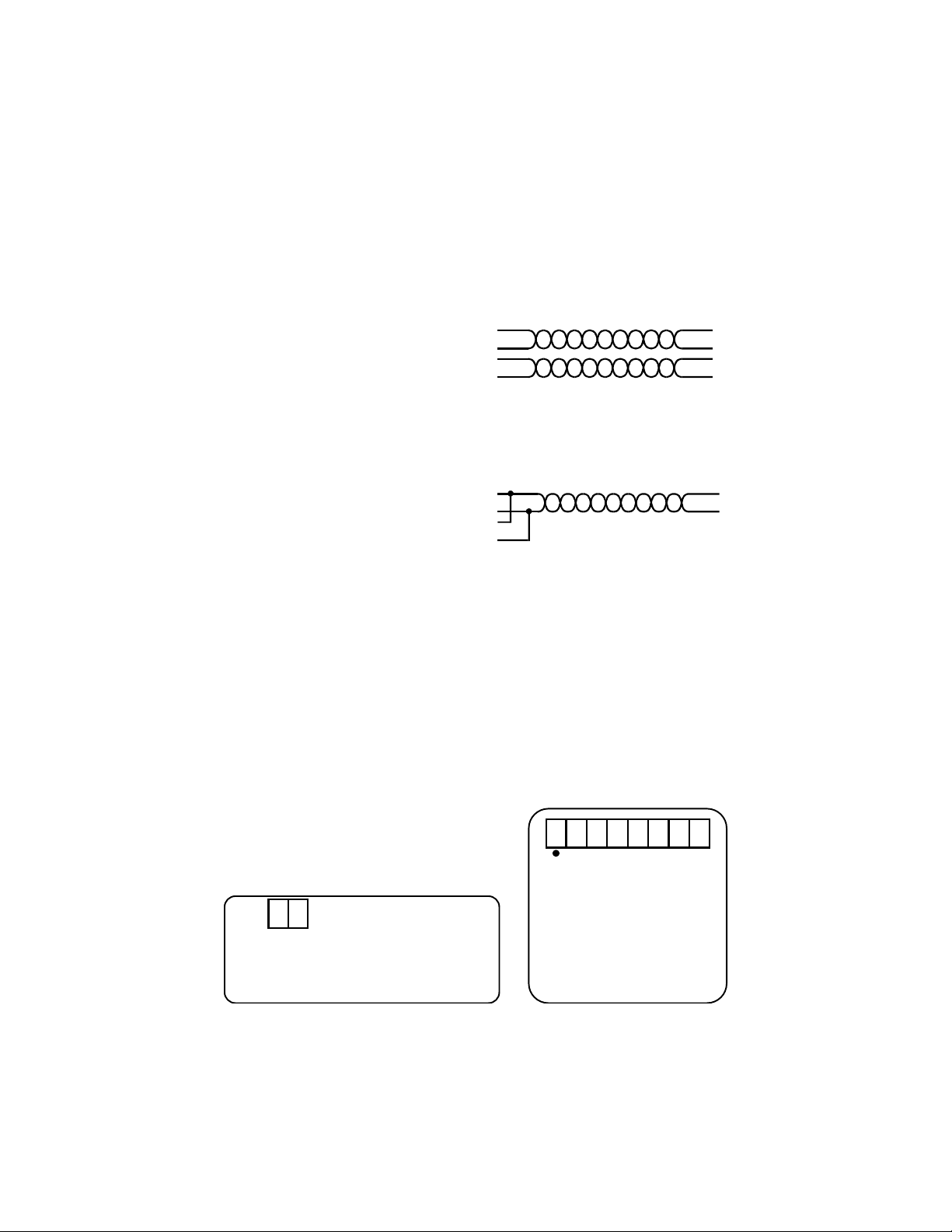
Type B
plug and receptacle
Appendix E
USB Cabling Diagrams
Type A
plug and receptacle
10
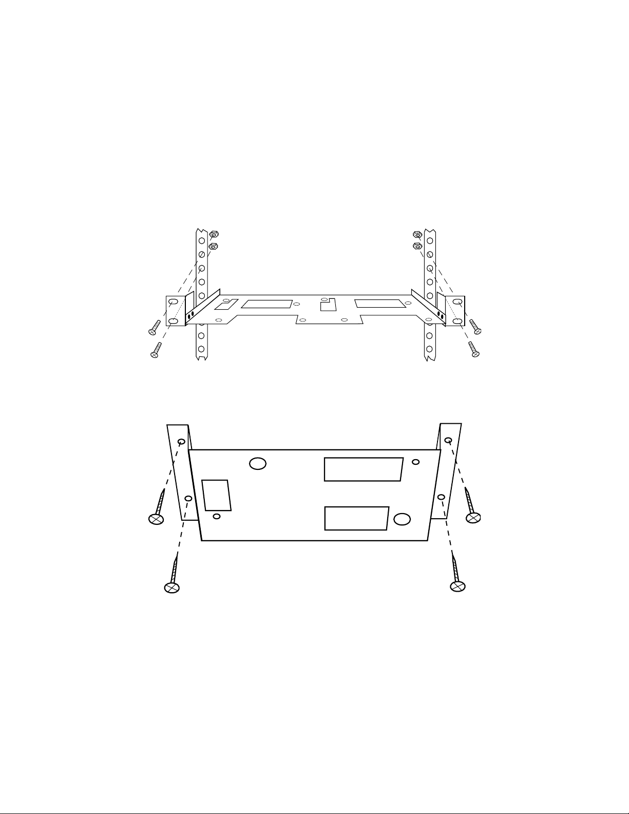
Under-Shelf Mounting Bracket
Appendix F
Mounting Diagrams
Rack Mount Kit
Nuts, bolts, and screws are not included.
11

12
Revision Date (Page(s)/ Location ) Change
A 10/98 (all) Original
B 07/01 (all) renumbered pages with title page starting as “1” and updated
all page number references, (front cover) removed part numbers,
(inside cover) removed stacking instructions, (1) added title page
with TOC, (2) moved the fine print from end of guide, updated ad-
dress, changed year in copyright notice, (3-5) updated installation
procedures on the various platforms, (9) added cabling diagrams,
(10) added mounting diagrams, (back cover) added document part
numbers and logo, updated address
Revision History

(This page intentionally left blank.)

www.ionetworks.com
support@ionetworks.com
telephone: (512) 306-0600
facsimile: (512) 306-0694
Inside Out Networks
7004 Bee Caves Rd.
Bldg. 3, Ste. 200
Austin, TX 78746
400-1005-01 Rev B (printed version)
400-1005-02 Rev B (electronic version)
This manual suits for next models
2
Table of contents
Other Inside Out Networks Media Converter manuals


