3M 09/06 PRINTED IN USA
Information and specifications subject to change without notice
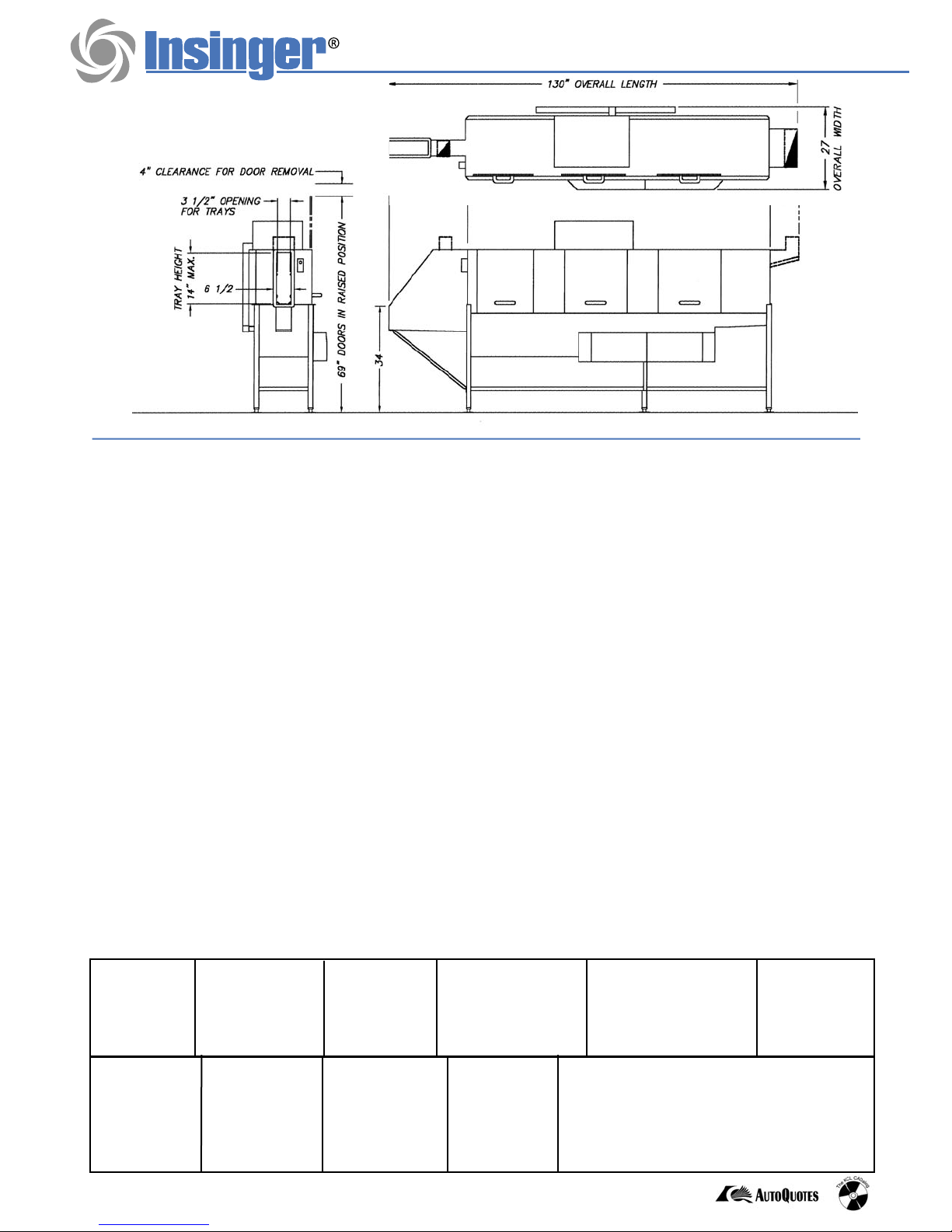
Note: For all rough in connections see Installation and Layout Detail Drawing.
SPECIFICATIONS
CONSTRUCTION - Hood and tank constructed of 16 gauge type 304 S/S. Hood all welded seamless construction.
S/S frame, legs and feet. All internal castings are non-corrosive lead free nickel alloy, bronze or S/S investment.
DOORS - Three large die formed type 304 S/S front inspection doors riding in all S/S channels. No plastic sleeves or liners used.
Two intermediate S/S safety stops on each door.
CONVEYOR - One S/S roller conveyor chain with tray cradles. Width between guide rails is factory adjustable from 1.5” to
3.5”. Conveyor accommodates trays up to 14” high. Conveyor drive system includes variable speed gear motor with frictionless,
trouble-free overload system. Trays conveyed automatically through washing and rinsing sections.
PUMPS - Centrifugal “packless” pump with brass petcock drain. Ceramic seal and balanced cast impeller on a precision
ground S/S shaft. All rotating parts mounted and removed as an assembly without disturbing pump housing. 1/2 hp prewash
motor, 3 hp wash motor, and 2 hp rinse motor, all standard TEFC C-face frame, with ball bearing construction.
CONTROLS - Top mounted NEMA 4X control enclosure, with thermal insulation between hood and enclosure, housing
motor controls with overload protection, transformer, contactors and all traywasher integral controls. All controls safe
low voltage 24 VAC.
SPRAY SYSTEM - All spray systems made of type 304 S/S pipe. Prewash, wash, and rinse assemblies removable
without use of tools.
PREWASH - Two vertical spray arms (one on each side of conveyor), each with 5 V-jet nozzles
WASH and RINSE - Four spray arms threaded into S/S manifold (2 on each side of conveyor). Each arm designed with
8 high pressure spray slots. Slots are precision milled for water control and produce a fan spray.
FINAL RINSE - Two vertical spray arms (one on each side of conveyor), each with 6 V-jet nozzles. Arms enclosed in
shrouded final rinse chamber to maximize heat transfer to trays.
DRAIN - Drain valves externally controlled. Overflow assemblies with skimmer caps are removable without the use of
tools for drain line inspection. Heaters protected by low water level control.
UNLOAD TABLE - S/S tray unload table receives clean trays. Table constructed with guide rails to ease trays onto table.
Capacity
per hour
Final rinse
consumption
at 20 psi min.
Exhaust
requirements Peak rate
drain flow
Shipping
weight Current draw
amps Steam Electric
Tank capacity Motor size Electric usage Final rinse
peak flow
at 20 psi min.
878 trays
197 gals./hr.
100 CFM Load
300 CFM Unload 23 gals./min. 1100 lbs.
11.2 gal. prewash
15.3 gal. wash
11.5 gal. rinse
1/2 hp (prewash)
3 hp (wash)
2 hp (rinse)
1/8 hp (conveyor)
8 kw wash tank
8 kw rinse tank
24 kw booster 40° rise
36 kw booster 70° rise
58 lbs/hr tanks
70 lbs/hr booster 40° rise
122 lbs/hr booster 70° rise 3.28 gals./min.
Steam
consumption
at 20 psi min.
208/3/60 .............. 22.9
................
67.3
240/3/60 .............. 20.8
................
59.2
380/3/60 .............. 12.6
................
37.0
480/3/60 ...............
10.3 ................
29.5
TRAC 878
CSI - 11400


