Insportline IN 7832 User manual

USER MANUAL –EN
IN 7832 Children’s Bike KAWASAKI Moto 12"
IN 3567 Children’s Bike KAWASAKI Shrimp 12"
IN 4171 Children’s Bike KAWASAKI Buddy 14"
IN 1843 Children’s Bike KAWASAKI Dirt 16"
IN 7834 Children’s Bike KAWASAKI Moto 16"
IN 1842 Junior Bike KAWASAKI Rebel 20"
IN 7839 BMX Bike KAWASAKI Kulture 20"

2
CONTENTS
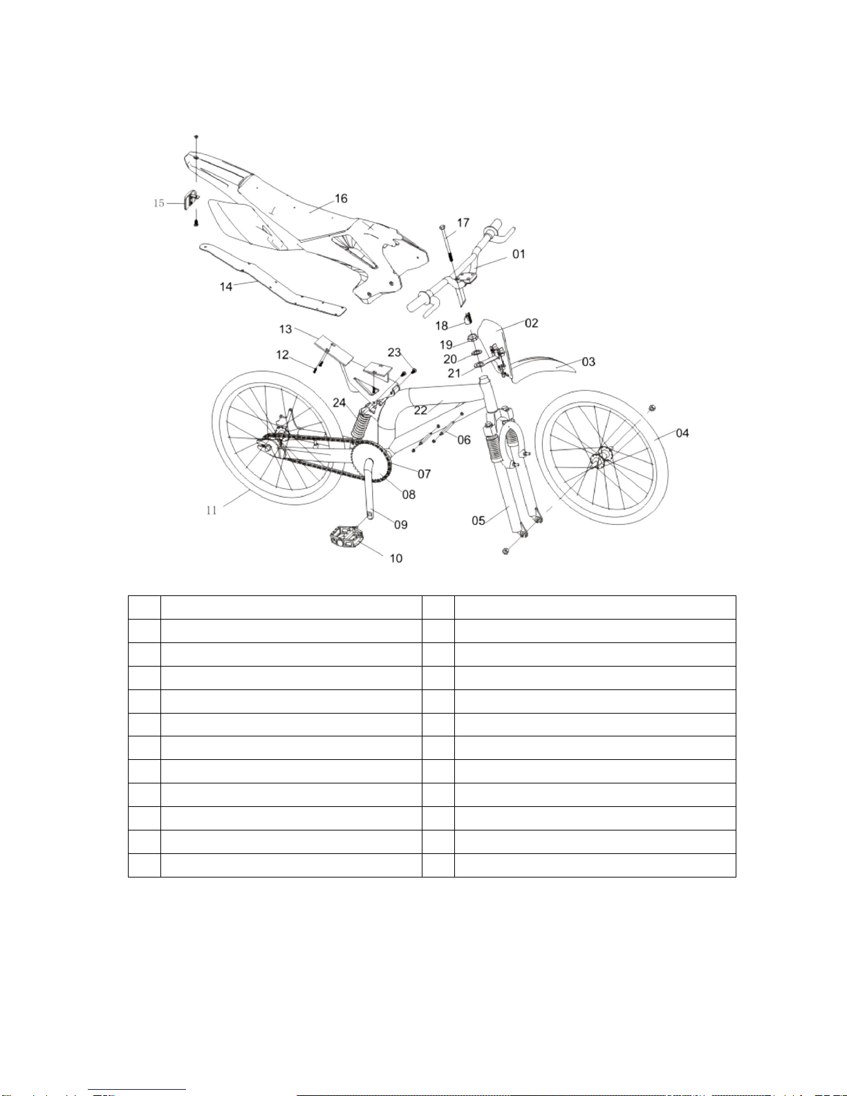
COMPONENTS....................................................................................................................................... 4
USAGE.................................................................................................................................................... 5
CHILDREN’S BIKES 12", 14", 16"....................................................................................................... 5
CHILDREN’S BIKES 20", 24", 26" ....................................................................................................... 5
INTRODUCTION..................................................................................................................................... 5
TIPS AND RECOMMENDATIONS...................................................................................................... 5
INFORMATION IN THIS MANUAL...................................................................................................... 6
TERMINOLOGY .................................................................................................................................. 6
SAFETY INSTRUCTIONS....................................................................................................................... 7
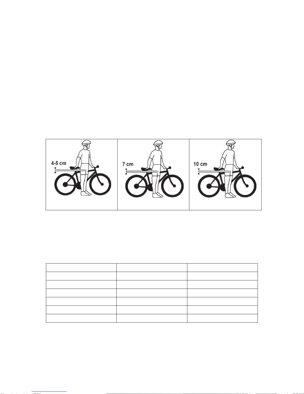
CHOOSING THE BIKE SIZE ACCORDING TO THE CHILD’S AGE AND HEIGHT .......................... 7
RECOMMENDATIONS/WARNINGS................................................................................................... 8
BEFORE FIRST USE.............................................................................................................................. 8
BEFORE EVERY USE ............................................................................................................................ 8
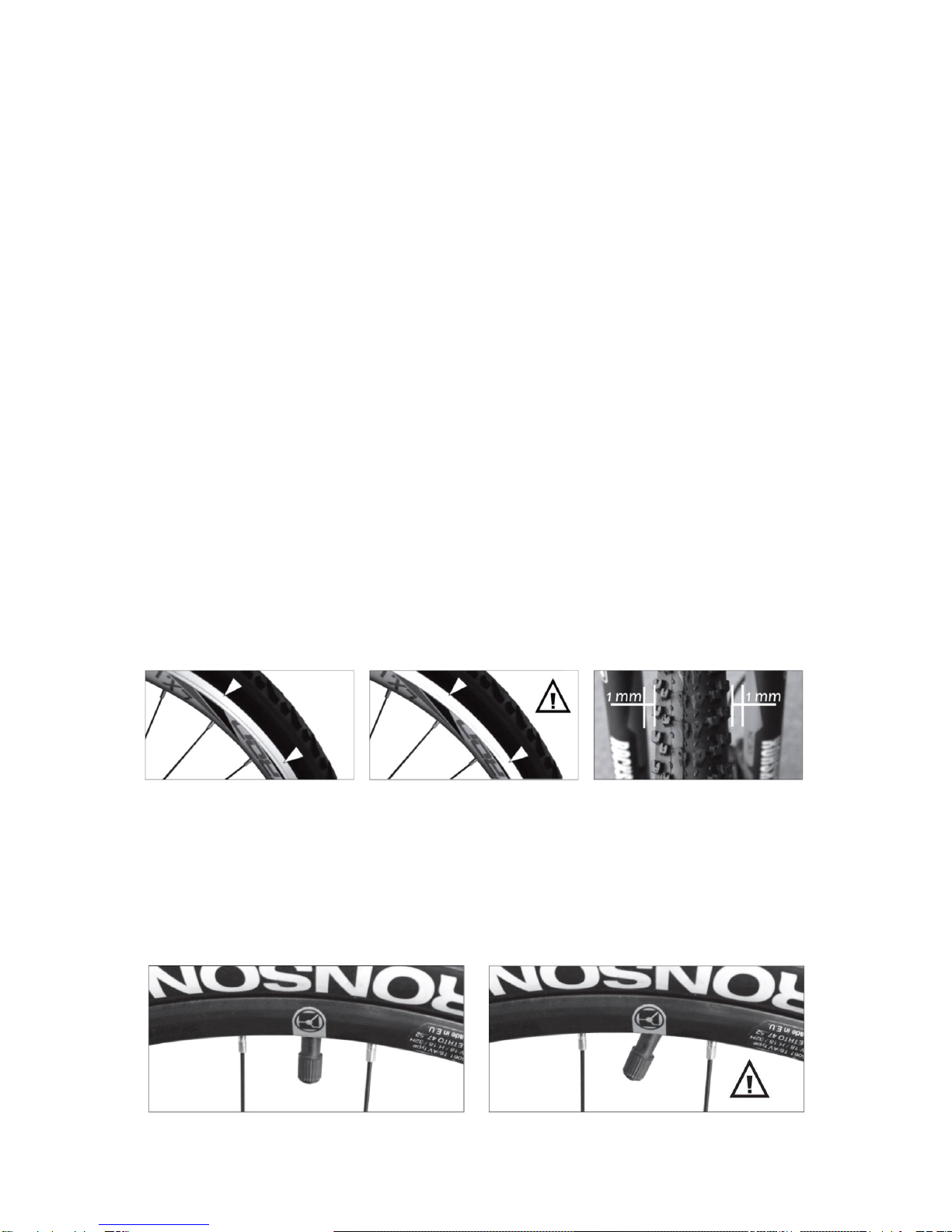
INSPECTING THE WHEELS............................................................................................................... 9
ASSEMBLY, MAINTENANCE AND SETTINGS................................................................................... 13
TOOLS/TECHNICAL SUPPORT....................................................................................................... 13
ASSEMBLY........................................................................................................................................ 14
SADDLE POSITION .......................................................................................................................... 16
REFLECTORS................................................................................................................................... 16
PEDAL ASSEMBLY........................................................................................................................... 18
SADDLE ASSEMBLY ........................................................................................................................ 18
BRAKE AND BRAKE CABLE ASSEMBLY........................................................................................ 19
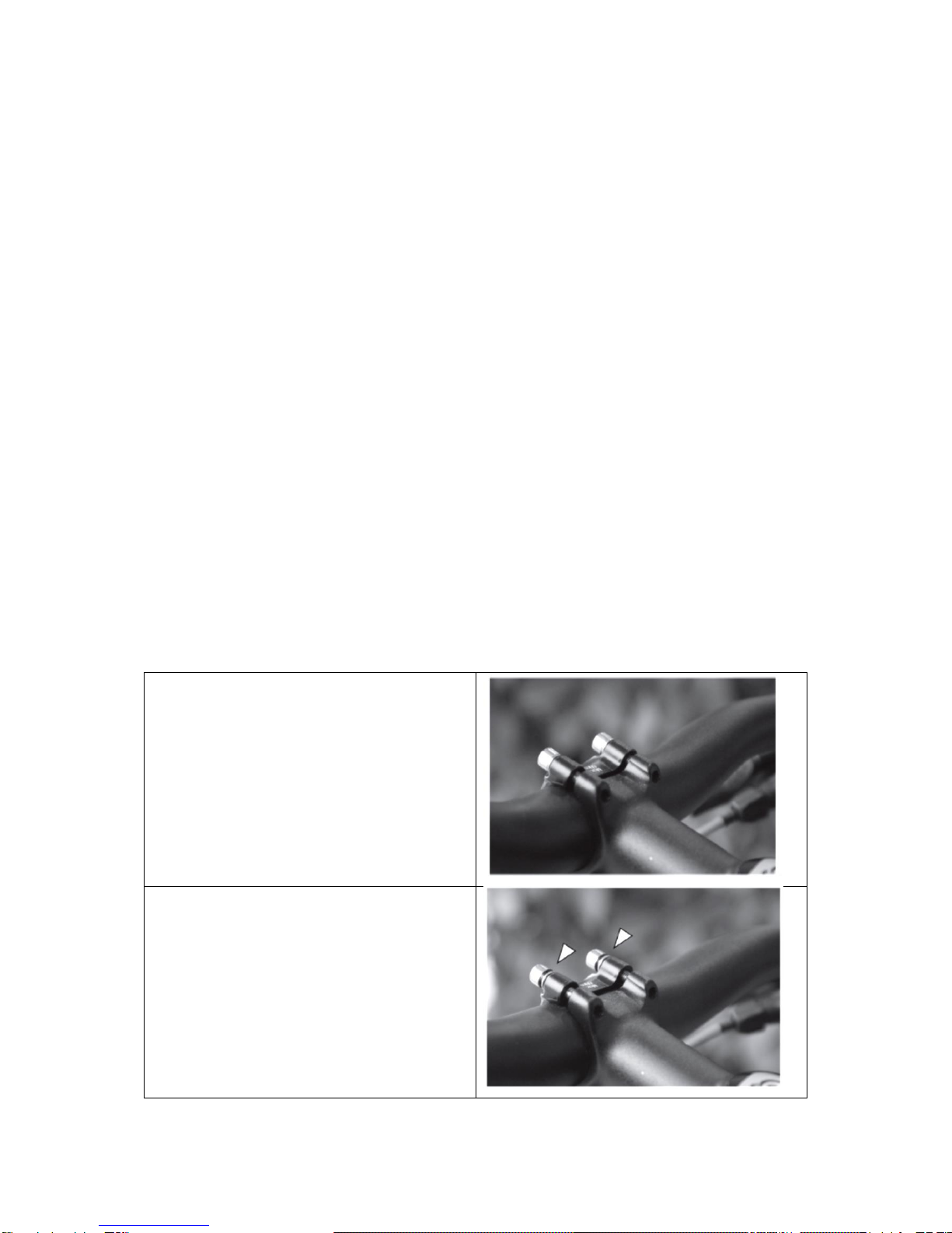
STEM AND HEADSET ASSEMBLY (4 BOLTS)................................................................................ 19
STEM AND HANDLEBAR ASSEMBLY (1 BOLT)............................................................................. 20
AFFIXING THE FRONT WHEEL TO THE FORK.............................................................................. 21
BRAKE SYSTEM............................................................................................................................... 22
ADJUSTING THE REAR DERAILLEUR............................................................................................ 25
CHAIN.................................................................................................................................................... 25
SHOCK ABSORBER WITH STEEL SPRING.................................................................................... 26
TIRES................................................................................................................................................. 26
TIRE REPLACEMENT....................................................................................................................... 26
TRAINING WHEELS ............................................................................................................................. 27
AFFIXING THE TRAINING WHEELS ONTO THE BIKE................................................................... 28
REPAIRS AND MAINTENANCE........................................................................................................... 28
SPROCKET-WHEEL/CHAIN............................................................................................................. 29
TIRES................................................................................................................................................. 29
WHEELS............................................................................................................................................ 29

3
BEARINGS......................................................................................................................................... 29
LUBRICATION....................................................................................................................................... 30
ONE-PIECE CRANKS ....................................................................................................................... 31
CLEANING AND MAINTENANCE ........................................................................................................ 31
STORAGE............................................................................................................................................. 32
TORQUE OF THE CONNECTING MATERIALS .................................................................................. 32
RIDING RECOMMENDATIONS............................................................................................................ 33
SERIAL NUMBER ................................................................................................................................. 34
TERMS AND CONDITIONS OF WARRANTY, WARRANTY CLAIMS................................................. 34

4
COMPONENTS
Picture includes all components mentioned in this manual.
1.
Handlebars
13.
Seat holder
2.
Protector with number
14.
Seat support
3.
Front mudguard
15.
Rear reflector
4.
Front wheel
16.
Saddle
5.
Front fork
17.
Stem screw
6.
Inner threaded casing
18.
Wedge
7.
Chain
19.
Headcap
8.
Chainring
20.
Cap
9.
Crank
21.
Front mudguard holder
10.
Pedal
22.
Frame
11.
Rear wheel
23.
Safety screws
12.
Bolt
24.
Frame suspension
The picture above is only illustrative.

5
This manual only includes safety, use and maintenance instructions. Read the entire manual
before using the bike for the first time and keep it safe for possible future use. Follow the
instructions in this manual and be sure to tighten all connections correctly.
By buying this product you take responsibility for your safety. The manufacturer, distributor, seller or the
employees of the public services are not responsible for any injuries that might occur. Follow every
safety precaution while riding the bike.
USAGE
CHILDREN’S BIKES 12", 14", 16"
The maximum seat height of bikes in this category is 435 –635 mm. The maximum seat height is the
measured vertical distance from the top of the saddle to the ground, provided the saddle is horizontally
inclined and the seat post is set to its maximum possible height. These bikes are made for the most
junior riders. Taking into account the probable skills and abilities of young children, the bikes are suitable
mainly for flat and hard surfaces (playgrounds/training grounds). If you use the bike on public roads, you
need to equip both the bike and the child with all necessary protective features. The weight limit for the
12", 14" and 16" children’s bikes is 40 kg. The total weight (the rider + bike + baggage) should not
exceed 50 kg.
CHILDREN’S BIKES 20", 24", 26"
The maximum seat height of bikes in this category exceeds 635 mm. These bikes are made for young
cyclists and can be used on every type of terrain. If you use the bike on public roads, you need to equip
both the bike and the child with all necessary protective features. A certain skillset is required to control
these models. The weight limit for the 20", 24" and 26" children’s bikes is 90 kg. The total weight (the
rider + bike + baggage) should not exceed 100 kg.
CAUTION: Only use this product for the purposes it was designed for. If you do not use this bike in a
proper manner, you endanger yourself and risk a fall or a collision. If you ride the bike on difficult terrains,
its components can be damaged, perhaps irreparably. Riding a bike with damaged components is
dangerous and can lead to falls or collision. Only ride on a terrain the model of your bike is suited for.
INTRODUCTION
TIPS AND RECOMMENDATIONS
Always wear a bicycle helmet that meets the local safety standards.
Consult local legislature to find out up to what age are bicycle helmets compulsory.
Make sure any parts of your body, clothes or other objects do not make contact with the sharp
edges of the derailleurs, pedals, the chain or the training wheels.
Always wear fitting shoes that do not slip form the pedals. Do not ride with unsuitable shoes.
Wear visible clothes, if possible made of reflective materials or complemented with reflective
straps.
Learn how to use the bike thoroughly; consult the seller if necessary.
Jumping, riding on a ramp, or riding through difficult terrain can damage the bike and cause a
serious injury.
Always inspect the bike before using it.
Parental disclaimer:
As a parent or a guardian, you are responsible for your child’s activities and safety. It is your
responsibility to ensure your child is properly instructed on how to use the bike. Take extra care to
explain the brake system, especially if the bike has a coaster brake.

6
Parents and guardians are also responsible for choosing the correct bike size and ensuring the bike is
in perfect condition. Some parents purposely choose bigger bikes for their children in an effort to save
money. However, this is dangerous for the child as they cannot feel safe on an oversized bike that is
hard for them to control. In such situations the risk of an accident increases. Most bicycle riding accidents
happen to children. An oversized bike can also have negative effects on the growth of the child’s bones
and muscles, because it is impossible to set the seat correctly.
INFORMATION IN THIS MANUAL
If you do not adhere to the instructions in this manual, you risk causing a fall, injury or material
damage.
Before using the bike, read the entire manual first.
Keep this manual and in case the owner changes, hand it over along with the bike.
If you find the instructions in the manual unclear or have additional questions, contact the
seller.
It is not the purpose of this manual to teach the user how to ride the bike or to improve their
riding technique.
Taking into account the variety of bicycle components, this manual does not provide
information about every one of them.
Always follow the seller’s recommendations.
Children’s seats and carriers cannot be affixed to children’s bikes.
TERMINOLOGY
Orientation –“left, right, front and rear” are described from the view of the rider
Authorized dealer –seller-approved manufacturer at the time of the purchase
Authorized service –after-sale service and maintenance.
Correct tightening –situation where the screw
head is tightened with the recommended amount
of force (N m).
Incorrect tightening –situation, where the
screw is not screwed fully or by the
recommended amount of force (N m).

7
Bar –pressure unit, 1 bar = 100 000 Pa
Psi –American pressure unit, 1 psi = 0.06897 bar
N m –unit of torque
Chainring –the biggest chainring has the most teeth, the smallest has the least
Sprocket-wheel –the biggest sprocket-wheel has the most teeth, the smallest has the least
Freewheel –a system of several chain wheels
Cassette –part of the hub that holds the freewheel
SAFETY INSTRUCTIONS
The rider should be able to keep balance on the bike and control the speed and direction with the
provided braking system.
The size of the bike must complement the rider’s stature. We recommend to choose the bike size
according to the picture below. Standing astride the assembled bike, the rider’s groin should not touch
the top tube.
Tarmac surface
Uneven surface
Rough surface
If you intend to use the bike on tarmac surfaces, the distance between the frame and your groin should
be 4 –5 cm. If you plan on riding on uneven terrain, the distance should be 7 cm. The optimal distance
for riding on a rough terrain is 10 cm. Consult the bike size with the seller.
Do not forget that every road and pavement can have uneven parts, that can endanger the rider or
damage the bike.
CHOOSING THE BIKE SIZE ACCORDING TO THE CHILD’S AGE AND HEIGHT
Wheel diameter
Child’s age
Child’s height (cm)
12"
2 –4
90 –110
14"
3 –5
95 –115
16"
4 –7
100 –125
20"
5 –9
105 –135
24"
8 –12
115 –155
26"
9+
130+
While riding on public roads, make sure your bike is equipped with all the required components (brake
system, reflectors, lights, bell, etc.). It is recommended to familiarize yourself with local legislation and
consult the seller, if necessary.

8
Use a bicycle helmet. For maximum safety, choose the size and type according to the seller’s
recommendations (riding style is an important factor).
Correct helmet position:
Incorrect helmet position:
DANGER: If you decide to replace one of the components, it is recommended to use a component
compatible with your bike. You may also want to consult the manufacturer. If you do not have sufficient
experience or tools, contact the seller. Any amateur modifications may damage the bike and cause a
serious injury or death.
RECOMMENDATIONS/WARNINGS
It is recommended to be extremely careful while riding on public roads (for better safety,
always yield the right of the way).
Keep in mind that the brake system’s effectivity decreases on wet surfaces.
Wear comfortable sportswear that cannot get caught in the moving parts of the bike.
If you ride through worsened visibility conditions (dawn/twilight, at night or in bad weather),
equip yourself with suitable reflective features and lights.
Do not overload the bike. Consult the seller if necessary.
Carefully read all instructions in this manual.
Always wear a helmet while riding a bike.
BEFORE FIRST USE
DANGER: If you use a bike not suited for riding on public roads, you risk falling, collisions, material
damage or death.
Familiarize yourself with all the bike’s features before using it for the first time. Try out the brake levers
and see which wheel they control. For your safety, we recommend you try the brakes out while riding
slowly at first, gradually picking up speed. The effectivity of the brakes increases with the intensity of the
braking. If you use clipless pedals, practise fastening and unfastening them before riding the bike. Find
a free space to practice, away from traffic or pedestrians. You’ll be ready for the first ride only after
inspecting the entire bike and reading through this manual.
BEFORE EVERY USE
DANGER: If you use a bike without a complete or original components set, you risk an injury or material
damage.
Make sure you remember the state the bike was in after the initial setting (by the seller) so you recognise
any unusual changes. If you register such changes, take the bike to the seller for repairs.
Inspect the entire bike before every ride –the tightening of all connections, possible deformations,
scratching or other mechanical damage.

9
INSPECTING THE WHEELS
The wheel size depends on the purchased model:
1. 12" –wheel diameter: 203 mm + tire
2. 14" –wheel diameter: 254 mm + tire
3. 16" –wheel diameter: 305 mm + tire
4. 20" –wheel diameter: 406 mm + tire
Wheel components:
Hub
Cassette (on the rear hub)
Brake disc (if the bike has disc brakes)
Spokes
Rim
Tire
Tube (there are models without them)
Rim protection strap
INSPECTING THE CONNECTION OF THE WHEELS
Try to shake both wheels in every direction. The wheels cannot be loose and there shouldn’t be any
strange noises, e.g. creaking.
INSPECTING THE RIMS
The wheels should not be dirty. They especially shouldn’t be covered in oil. Remove oil stains
immediately.
Check the rims for wear and replace them if necessary.
There should be no scratch marks or striations. Check the rim by tracing your nail along the brake area.
If you discover any unevenness, consult the seller.
Lift up the front and rear wheel, spin them and check the distance between the rim and brake pads (rim
brakes) or between the rim and the fork (disc brakes). Maximum deviation is 1 mm, otherwise it is
necessary to centre the wheel.
You need specific tools and skills to inspect the bike as described above. It you are not experienced in
this area or don’t have the necessary tools, request assistance from the seller.
INSPECTING THE TIRES

10
1. Valve position
NOTE: Doesn’t apply to tires without tubes.
DANGER: If the valve nipple is not in a vertical position (doesn’t line up with the position of the
hub), there is a danger of it breaking off which would result in rapid pressure drop. This may
cause material damage or loss of control on the bike.
2. Pressure check
DANGER: Underinflated tires are more likely to be punctured and make the ride more
dangerous. The tire can slip from the rim on an uneven surface and move along the rim which
can cause falls, collisions, or material damage. Always inflate the tires with optimal pressure.
NOTE: Most manufacturers use the psi unit to denominate pressure on the tire. To metricize,
use the following table.
Psi
30
40
50
60
70
80
90
100
110
120
130
140
Bar
2,1
2,8
3,5
4,1
4,8
5,5
6,2
6,9
7,6
8,3
9,0
9,7
The optimal pressure can be found on the tire or in the provided rim instructions. The optimal
pressure can usually be found on the side. If you have any trouble, contact the seller.
NOTE: The higher the weight of the rider, the more pressure is needed to inflate the tire.
Check the pressure with a pressure gauge (offered by the seller). If the pressure is too low, use
a pump to pressurize it. If the pressure is too high, open the valve and let the air out. It is
recommended to use a pressure pump with inbuilt gauge, so you can check the pressure while
inflating the tire.
NOTE: There are several valve types: Schrader valve, Presta valve and Dunlop valve.
Presta valve
Dunlop valve
Schrader valve
3. Inspecting the tire surface
Lift up and slowly spin both wheels. Check the side and the top of the tire. The tire’s surface
must be flat everywhere. There cannot be any bulging and the texture must be undisturbed. The
material should not peel off or be damaged in any way. Check the rims also.
INSPECTING THE SADDLE AND SEAT POST
DANGER: If the seat post is not properly inserted into the frame, it can get loose and cause a fall,
collision or material damage.
1. Check that the seat post is firmly affixed to
the frame.
Grab the saddle and try to move it to the side. The
saddle and seat post must not move in any way.

11
2. Check that the saddle is affixed well to the
seat post.
Try to move the saddle up and down. The saddle
cannot move.
If you have the KAWASAKI Kulture 20" model, check whether the screws are tightened correctly.
INSPECTING THE STEM AND THE HANDLEBARS
DANGER: The handlebars and the stem are incredibly important for your safety. Their damage or
incorrect assembly can lead to serious injuries. If there is a problem with these parts of the bike or you’re
unsure, do not use the bike and consult an appropriate customer service.
Check the position of the stem and the handlebars with regard to other parts of the bike. The stem must
be aligned with the front wheel rim and the handlebars must be at right angle. Grip the front wheel with
both legs. Grab the handlebars and try to steer them sideways. Also try to move the handlebars inside
the stem. None of the components should be loose and there shouldn’t be any creaking.
INSPECTING THE HANDLEBAR ASSEMBLY
Grip the front wheel with your legs. Make sure the brake levers are tightly attached and that the grips
hold onto the handlebars. None of these components can twist or shift. There should be no strange
sounds. If you decide to affix a bell to the handlebars, make sure it holds tightly and that you can easily
reach for it while on the bike.
INSPECTING THE HEAD SET
If you want to inspect the head set, you must brake the front wheel
(manually) and repeatedly move the bike front/back. There shouldn’t be
any noise and the connections should hold tightly. Then lift up the rear
wheel above the rest and shift the front wheel so that it’ll be at right angle
to the frame. Once you loosen your hold on the handlebars, the front
wheel should align with the frame again.

12
INSPECTING THE BRAKE SYSTEM
DANGER: Defective brakes can endanger your life. Inspect the brakes carefully.
1. Inspecting brake pads/shoes
Firmly squeeze the brake levers so that the brake pads/shoes grip the rim/disc (the distance
between the lever and the grip should be 35 mm). The wheels should be locked completely
once you try to move them. The right lever brakes the rear wheel, the left brakes the front wheel.
2. Inspecting rim brakes and cables
It is important to keep the cables clean and in a good condition. The adjusting screws
should be securing them tightly.
Check the state of the screws by squeezing the braking levers –the range of movement
should not be excessive (you should not be able to squeeze the levers fully).
The brakes are functioning correctly, if the entire brake shoe surface touches the rims when the
lever is squeezed and if the brake shoes are in line with the rim. After releasing the lever, the
distance between the rim and the brake shoe should be the same on both sides. If you have rim
brakes, it is important to check the brake shoes regularly for wear. The brake shoes’ rabbets
mark maximum possible wear.
3. Inspecting coaster brakes
You brake by back pedalling.
Check if the brake arm is sufficiently tightened to the frame. You should not have to back
pedal for more than ¼ spin. With drum brakes, visually check the cables and all
components (the inner mechanism can be checked only by authorized professional).

13
4. Inspecting hydraulic and disc brakes
DANGER: The brake system can fail completely if there is too much dirt on the brake discs. In
such a case, carry out maintenance immediately.
SCORCH RISK: The discs may heat up if used intensively. If you touch them, you can suffer
burns.
Check the brake caliper by trying to turn it in every direction. The caliper should hold tightly and
should not be able to move in any direction.
Check the brake lubricant by squeezing the brake levers with maximum force and then
looking for any lubricant leakage.
The brake discs cannot be bent, scratched or otherwise mechanically damaged.
Check the brake disc –lift the wheel off the ground and spin it. It should spin silently and
there should be no resistance.
Check the brake discs/pads for wear (instructions above).
NOTE: The brake discs, pads and calipers can significantly wear during several-day rides.
That’s why it is recommended to bring spare calipers and pads with you. However, some skill
and knowledge is required to replace these components. Consult the seller if necessary. If you
feel you cannot replace these components by yourself, ask a qualified professional for help.
5. Inspecting mechanical disc brakes
Checking the cables is described in point 2, checking the calipers in point 4.
INSPECTING THE CRANKS AND THE CHAIN
1. Squeeze the cranks to the frame (as depicted).
You should not be able to otherwise move them
and they should not make any noise during a ride.
2. Don’t forget to check the chain. It should be clean
and the links cannot be deformed. When you spin
the pedals back, the chain should move freely
without falling off.
ASSEMBLY, MAINTENANCE AND SETTINGS
TOOLS/TECHNICAL SUPPORT
The bike was assembled in a manufacturing plant and later partly disassembled for easier transport. It
is possible the bike was assembled again before purchase. It can also be sold disassembled in the
original package. If you act according to the following instructions, you’ll ensure the bike’s longevity.
Follow the instructions and check if you have all the parts and tools necessary to complete the assembly.
Read the following chapters for detailed information about maintenance, settings, adjustments and
lubrication of your bike. Contact us if you have any further questions or need additional spare parts.

14
Tools needed for assembly:
Philips screw driver: 4 mm, 5 mm
Allen wrench: 6 mm, 8 mm
Screw-wrench or a nut wrench: 9 mm,
10 mm, 14 mm, 15 mm
Wrench and socket wrench
Pliers to cut wire
You’ll avoid injuries only if the bike is correctly assembled and set. If you purchased an already set bike,
it is recommended to check it according to the manual before using it. Make sure that the bike was
supplied with all the necessary assembly and adjustment instructions.
ASSEMBLY
Taking into account all the model varieties, this manual is generalized. Should you have a problem with
the assembly, contact the customer service.
Place the front wheel in the center of the
fork and screw the nuts to the wheel
with the supplied nut wrench.
Screw the bolts on the seat holder with
the supplied Allen wrench.
Assemble the upper part of the headset,
Slide the front mudguard onto the fork
tube and then put the disassembled part
of the headset back. Tighten with the
supplied nut wrench.

15
Slide the handlebars into the steering
tube so that they’re aligned with the
front fork and screw the expanding bolt
with a wrench.
Screw dowels into the lower frame lube.
Affix the saddle onto the saddle holder
with bolts and nuts.
Screw the right pedal (marked with R) to
the right crank (the side with the chain).
Screw clockwise. Then screw the left
pedal (marked with L) to the left crank.
Screw the left peal anti-clockwise.

16
Put the rear reflector to the hole in the
rear mudguard and affix it with bolts.
SADDLE POSITION
It is not possible to adjust the seat height with some models.
Choosing the right size:
Stand next to the assembled bike with legs astride at
shoulder level.
The gap between the highest frame point (1) and the
user’s groin should be approx. 2.5 cm.
The user’s legs should reach at least 2.5 cm above
the highest point of the frame (3).
The rider needs to be able to reach the brake levers
and use them comfortably (if they are a part of the
bike).
REFLECTORS
The bike is outfitted with reflectors. A front reflector (white),
a rear reflector (red), two wheel reflectors (white) and two
pedal reflectors (orange). Having reflectors on a bike is
required by legislature and very important to your safety.
They should be kept clean and properly affixed. Check the
reflectors, holders and connections regularly. Replace any
damaged components.

17
INSTALLING THE FRONT REFLECTOR
NOTE: After assembling the bike, check the placement of
the reflectors. The reflectors should always be vertical.
Installing reflector onto the handlebars:
Attach the holder with the white reflector so that the
reflector faces straight ahead (A).
After setting the reflector’s position, affix the holder with a
fixing bolt –tighten with screwdriver.
INSTALLING THE REAR REFLECTOR
1. Loosen the screws on the rear reflector holder
and set the reflector into the correct position.
2. The rear reflector must be vertical and facing
backwards.
3. There should be at least 7.5 cm gap between the
reflector and the edge of the saddle.
Maintenance
WARNING! For your safety, do not use the bike if the reflectors are missing, damaged or not properly
set. Make sure both rear and front reflectors are vertical. Be careful not to cover the reflectors with
clothes or other materials. Keep the reflectors clean with the help of a soap and a wet cloth.

18
PEDAL ASSEMBLY
The pedals are marked with L or R (left/right).
1. Screw the right pedal (R) clockwise to the right-
side crank (the side with the chain).
2. Screw the left pedal (L) to the left-side crank.
NOTE: Screw the pedals manually first, so that you do not
damage the thread. After tightening it with a wrench, make
sure it is threaded fully. If the wrench is too thick, it’s range
may be limited.
SADDLE ASSEMBLY
Insert the seat post onto the bike frame –the bent
end upwards.
NOTE: Insert the seat post at least up to the minimum
insertion point. If the point is not marked, insert at least
7.5 cm of the seat post.
Tighten the seat post clamp –recommended torque
= 13.6 N m.
Loosen the saddle clamp and attach the saddle to
the seat post.
Tighten the saddle clamp –recommended torque =
17 N m.
SADDLE HEIGHT
1. Step on the pedal so that it is in its lowest position.
2. Put your heel onto the pedal, so that your foot is
parallel to the ground.
3. Adjust the seat so that you can reach the ground with
the toes of your other foot. The saddle should be
parallel to the ground and aligned with the frame.
4. Tighten the seat post clamp –recommended torque
= 17 N m.
NOTE: Insert the seat post at least up to the minimal
insertion point.

19
HORIZONTAL POSITION OF THE SADDLE
1. Step on the pedal so that it is in its lowest position.
2. But your foot on the pedal parallel to the ground.
3. Adjust the saddle so that your knee and the pedal
align in a vertical position to the ground. Some
cyclists prefer to have the saddle a little more
forward.
NOTE: The saddle should be parallel to the ground
and aligned with the frame.
4. Tighten the saddle clamp fully.
BRAKE AND BRAKE CABLE ASSEMBLY
1. Connect the cable to the brake lever –open
the lever and insert the cable end.
2. Thread the cable through the adjustable bolt
and safety nut. Tighten the safety nut.
3. Attach the brake to the fork with a screw and
tighten it.
4. Pull on the cable until the brake pads are
touching the rims and then tighten the brake
screw.
Check that the brake pads are in contact and aligned
with the rims.
See chapter about setting the brake system.
STEM AND HEADSET ASSEMBLY (4 BOLTS)
1. Compression bolt
2. Handlebars
3. Upper headset cover
4. Stem
5. Side bolts
6. Headset
7. Frame

20
NOTE: The headset and the stem are already assembled. It is necessary to adjust both parts at the
same time.
1. To adjust the headset or the stem, loosen the side bolts first.
2. Adjust the stem so that it is aligned with the front wheel.
3. Tighten the compression bolt to affix the headset and the fork. If the fork cannot be freely
moved, the bolt needs to be loosened.
WARNING! Do not tighten the compression bolt too much. Its purpose is to adjust the headset.
The clamp screws affix the headset to the handlebars and the side bolts affix it to the fork.
4. Once the headset is adjusted, tighten both side bolts with 2.5 kg/mm (0.02 N m) torque. Make
sure not to tighten them too much.
WARNING! Do not tighten too much the screws/bolts that affix the headset to the handlebars and
the fork. It could have detrimental effect on the durability of the stem and the steering abilities of the
bike, which could result in a fall and injury.
STEM AND HANDLEBAR ASSEMBLY (1 BOLT)
1. Affix the stem to the fork: Thread a washer (5) through the bolt
(4), insert it into the stem (1) and screw on the wedge.
Do not screw the bolt (4) into the wedge (2) for more than 4 turns.
Turn the stem forwards, insert it onto the headset and adjust the
height according to your preferences.
WARNING! Insert the stem at least to the min. insertion point.
Otherwise, the stem may get damaged and a fall may occur.
Make sure the mark cannot be seen (is under the headset nut).
Slightly tighten the bolt on the stem - just so the stem won’t slide
into the headset.
2. Securing the handlebars onto the stem: Slide the handlebars
into the stem, set the stem to be aligned with the front wheel and
secure the clamp bolt.
3. Affixing the brake levers to handlebars: Release the fixing bolt
on the brake levers.
Shift the grip to the sides if necessary and put the levers onto the
handlebars –the rear brake lever goes onto the right handlebar.
4. Tighten the stem bolt and the brake fixing bolts:
WARNING! Be careful not to tighten the bolts too much –you could
damage the steering mechanism which could result in a fall.
This manual suits for next models
6
Table of contents
Other Insportline Bicycle manuals