Insta 414 User manual

MODEL 414
MNL90005
05/16/05 Rev.B
Operation and Maintenance Manual

THIS MACHINE IS DESIGNED TO BE OPERATED BY ONE OPERATOR ONLY
- 1 -
Congratulations!
Your selection of the Insta Graphic Systems®
(IGS) heat seal machine is a sound business
decision. IGS equipment is the result of the
highest quality engineering and time-tested
design. Your new machine combined with IGS's
reputation of innovation in the heat-seal
industry, insures the continuing capability of
delivering the best-decorated substrates possible.
This manual describes installation, operation,
and maintenance procedures for your new
model 414 machine.
Your model 414 machine will have a long
trouble-free life. Read this manual. Keep it with
your machine; it's your key to proper operation
and lasting service.
Installation
DOMESTIC
Use a 15 amp AC circuit. Only
industrial weight extension cords
with proper wire size should be
used: size 18/3 wire for distances up
to 25 feet, and size 16/3 for
distances up to 50 feet.
INTERNATIONAL
Only industrial extension cords
with proper wire size (2.5 mm sq.)
shall be used.
IMPORTANT
The appliance must be plugged into
a proper receptacle of the proper
size and rating. Equally important,
the line voltage must be able to
accommodate this appliance as well
as other appliances operating on this
circuit.
Specifications
Electrical 120 Vac, 50/60 Hz, 400 W
240 Vac, 50/60 Hz, 400 W
Weight 33 Pounds (14.5 KG)
Limited Machine Warranty
Insta Graphic Systems®(IGS) warrants this heat
seal machine, when operated under normal con-
ditions, to be free from manufacturing defects in
material and workmanship for a period of one
year on parts (lifetime on the upper heating
element) and 90 days on labor from the invoice
date.
This warranty will be effective only when IGS
authorizes the original purchaser to return the
product to the factory in Cerritos, California
freight prepaid, and only when the product
upon examination has proven to be defective.
This warranty does not apply to any machine
that has been subjected to misuse, negligence or
accident.
IGS shall not be liable for the injury, loss or
damage, direct or consequential, arising out of
the use or the inability to use the product.
No claim of any kind shall be greater in amount
than the sale price of the product or part to
which claim is made.
This is the sole warranty given by the company, it is
in lieu of any other warranties, expressed or implied,
in law or in fact, including the warranties of
merchantability and fitness for a particular use, and
is accepted as such by the purchaser in taking
delivery of this product.
Safety Summary
WARNING
In case of power cord damage, do
not attempt to repair or replace the
power cord. Contact the manufac-
turer or the local distributor.
WARNING
Avoid touching hot surfaces while
operating the machine.
CAUTION
During normal operation, the base
of the machine must be installed or
placed above the wall socket.

THIS MACHINE IS DESIGNED TO BE OPERATED BY ONE OPERATOR ONLY
- 2 -
Operation
1. It is recommended that you review the "How
to Apply Instructions" (in our Product
Catalog) before beginning heat sealing
operations.
2. Push ON/OFF switch to ON position. Set
desired temperature and lift handle so that
the upper platen arm is away from lower
platen.
NOTE
A setting of 8.5 on the temperature dial is
approximately 350°F (177°C).
CAUTION
The temperature adjustment knob gets
very hot during operation. Adjust
only when machine is cold.
3. Allow the machine to warm up for
approximately 30 minutes. When the
selected temperature is reached, the neon
lamp on the power switch will cycle on and
off.
NOTE
The thermometer indicates the internal
temperature of the heat platen and will
indicate a temperature approximately
15 degrees F (8.3 degrees C) higher
than the actual heat platen surface.
The temperature control is calibrated at
the factory and indicates the TRUE
surface temperature of the heat platen.
NOTE
The lower platen may be changed from
the standard platen to the special
custom platen by tilting the back of the
platen up and moving it towards the
operator. Install the alternate platen by
reversing the above procedure until the
platen locks in place.
NOTE
The lower platen may be adjusted to
accommodate various caps, sleeves,
pant legs, etc. Rotate the adjustment
knob located on the lower front of the
base. Clockwise rotation will move the
lower platen to the rear and counter-
clockwise rotation will move the lower
platen forward.
4. Set the desired pressure by adjusting the
pressure adjust knob on the top-rear of the
machine. To reduce pressure, turn knob
clockwise.
5. Place the substrate on lower platen. For a
cap, pull sweatband out, place crown on
lower platen, and lock the cap retainer by
pushing handle to the rear until it locks.
Smooth out all wrinkles.
6. Position transfer or lettering on substrate or
cap.
7. Close machine by pulling handle down into
locked position.
8. Set timer for desired time cycle.
9. The bell will ring at end of the time cycle.
Pull handle up slowly and move the upper
platen handle to its full open position. This
technique will avoid transfer paper (cover)
from being pulled off prematurely due to
suction from the separating platens.
10. Unlock cap retainer and remove substrate.
Preventive Maintenance Suggestions
The Insta Graphic Systems®(IGS) heat seal
machines are relatively maintenance free. For a
long, trouble-free life, the following preventive
maintenance steps should be followed:
1. Do not heat seal items such as buttons, pins,
snaps, or zippers which tend to cut the
silicone rubber pad or scratch the Teflon
heat platen.
2. Periodically clean the Teflon-coated heat
platen with a non-abrasive piece of cloth.
Stubborn stains may be cleaned, when
platen is cool, with mineral spirits.
3. When the heat platen is hot and not in use,
keep in open position (away from the
silicone rubber pad).
THIS MACHINE IS DESIGNED TO BE OPERATED BY ONE OPERATOR ONLY
- 3 -
4. To prevent soiling of substrate, periodic
wiping of the entire exterior machine,
including platens, with a clean rag is
recommended. If necessary, use mineral
spirits for cleaning a cold machine. Since
mineral spirits are flammable, use
precautions and keep away from sparks,
flame, or hot heat platen.
5. Occasionally apply a few drops of heavy
machine oil to the moving parts of the cam
assemblies and pressure adjustment screw.
NOTE
Wipe off any excess oil or grease.
Safety Summary
WARNING
In case of power cord damage, do
not attempt to repair or replace the
power cord. Contact the manufac-
turer or the local distributor.
WARNING
Avoid touching hot surfaces while
operating the machine.
CAUTION
During normal operation, the base
of the machine needs to be installed
or placed above the wall socket.
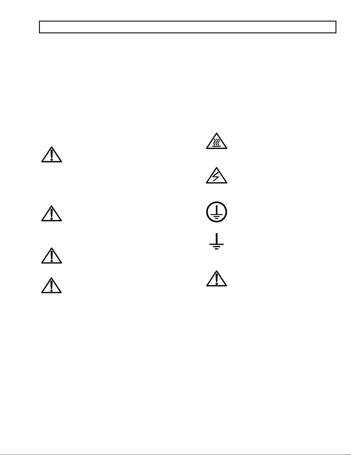
International Symbols
O
Power Off
I
Power On
Hot Surface
Risk of Electrical Shock
Protective Earth Terminal
Ground
Caution - Warning

THIS MACHINE IS DESIGNED TO BE OPERATED BY ONE OPERATOR ONLY
- 4 -
General Maintenance
It is recommended that you have the following
items available:
A. Regular screw driver
B. Phillips head screw driver
C. Small adjustable wrench
D. Needle nose pliers with insulated
handle
E. Set of Allen wrenches
F. Special high temperature grease
(MPPL023)
With the above items (not supplied with machine)
you should be able to accomplish most repairs.
WARNING
Power cord replacement should be from
the manufacturer only (because it
requires a specially prepared cord).
Replacement of Silicone Rubber Pads
1. Make sure heat platen is cool.
2. Use tube of MPPC006 adhesive to bond
silicone rubber pad to metal platen.
NOTE: Read instructions on the tube package.
3. Be sure that the surface of the silicone platen
is clean. Use a mild solvent such as mineral
spirits.
4. The pad and metal must be thoroughly dry
and clean, before starting the bonding
operation.
5. Apply adhesive sealant to the metal platen.
Spread a thin even coat and apply pad
immediately. Apply pressure and position pad
making sure that there is no air entrapment.
NOTE: A serrated blade such as used for laying down
rubber floor tiles would be helpful.
6. Allow to cure overnight under low pressure at
normal room temperature.
Temperature Control Replacement
NOTE
Disconnect Power Supply
1. Remove knob and shroud cover plate.
2. Disconnect the wires going to the control.
NOTE
The terminal with only one wire going
to it is the HOT side of the line. The
other terminal has two wires--one from
the heating element and one from the
lamp.
3. Remove the two temperature control
mounting screws.
4. Reconnect the three (3) wires to temperature
control as stated in Step 2.
5. Insert the two screws which secure the control
to the front of the heat platen.
6. Turn the control counterclockwise to the
minimum temperature position.
7. Replace the knob with the pointer indexed to
the zero "0" position.
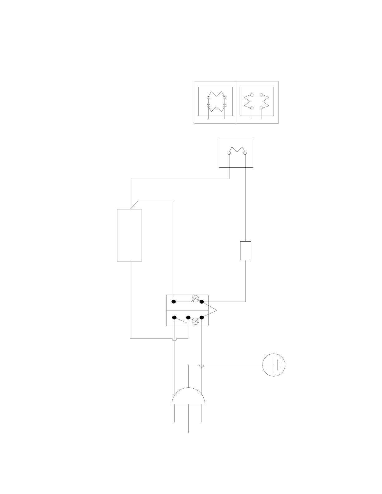
POWER SWITCH
WHITE
BLACK
TAN
TERMINAL
BLOCK
BLACK - USA
BROWN - EUR
GREEN - USA
GREEN / YEL EUR
WHITE - USA
BLUE - EUR
4
5
6
1
3
TAN
TAN
TEMPERATURE
CONTROL
UPPER PLATEN 407 120 VOLT
240 VOLT
UPPER PLATEN 414
1
120 AND 240 VOLT
POWER
INDICATOR
TEMPERATURE
INDICATOR
MODEL 407/414 WIRING - 05/16/2005
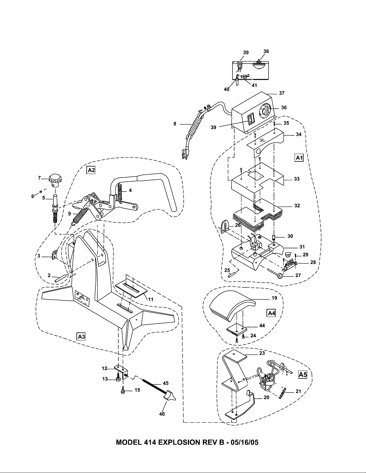

MODEL MODEL MODEL
414 414 414 EUR
NO PART NAME 120V AC 240V AC 240V AC
2 PIN, ROLL 3/8 x 2.500 LG MHPR38212 MHPR38212 MHPR38212
3 BRACKET, SPRING RETAINER MH412126 MH412126 MH412126
4 SPRING, HANDLE/HOLD DOWN MPSS454 MPSS454 MPSS454
5 SCREW, PRESSURE ADJ MPSP482 MPSP482 MPSP482
6 SCREW, SET 1/4-20 x .375 LG MHSST142038 MHSST142038 MHSST142038
7 KNOB, PRESSURE ADJUSTMENT MPPK018 MPPK018 MPPK018
8 POWER CORD (USA MODEL) MPPW141 MPPW162 N/A
8A POWER CORD (EUROPEAN MODEL) N/A N/A MPPW202
9 SPRING, RETURN MPSS453 MPSS453 MPSS453
11 PLATE, LOWER SLIDE MPSP450 MPSP450 MPSP450
12 BRACKET, ZEE RETAINING MH414312 MH414312 MH414312
13 SCREW, BOLT HEX 5/16-18 x .375 LG MHBH5161834 MHBH5161834 MHBH5161834
15 SCREW, BOLT, STRIPPER 5/16x.50 LG SLD.PL MPSS410 MPSS410 MPSS410
17 FEET, RUBBER (6/SET) (NOT SHOWN) MPF90004 MPF90004 MPF90004
19 PAD, SILICONE 3.25 x 6.25 MPPP024 MPPP024 MPPP024
20 CLIP, HANDLE CAP HOLD DOWN MPSC412 MPSC412 MPSC412
21 SPRING, HANDLE/HOLD DOWN MPSS454 MPSS454 MPSS454
23 SUPPORT ZEE MPSS471 MPSS471 MPSS471
24 SCREW, FLAT HD 1/4-20 x .625 LG MHSF142058 MHSF142058 MHSF142058
25 PIN, ROLL 3/8 x 1.50 LG MHPR38112 MHPR38112 MHPR38112
26 BRACKET, STABILIZER MH412312 MH412312 MH412312
27 THERMOMETER STEM (F/C) MPPT056 MPPT056 MPPT056
28 TEMPERATURE CONTROLLER MPPT032 MPPT032 MPPT032
29 SCREW, PAN HD 6-32x.250 LG. SELF TAPPING MHSP63214ST MHSP63214ST MHSP63214ST
30 INSULATORS, SPACER (4/SET) MPSI089 MPSI089 MPSI089
31 PLATEN, UPPER W/WIRING MPSP460 MPSP463 MPSP463
32 FIBERGLASS INSULATION MPSP249 MPSP249 MPSP249
33 SHROUD ASS’Y MPSS405 MPSS405 MPSS405
34 SHROUD, UPPER PLATEN (FRONT) MH41237 MH41237 MH41237
35 SCREW, PAN HD #10x1.00 LG PHIL SH METAL MPSS143 MPSS143 MPSS143
36 TIMER BELL MPPT058 MPPT058 MPPT058
37 HOUSING INSTRUMENT MH412211 MH412211 MH412211
39 SWITCH, POWER / INDICATOR ASS'Y MPPS230 MPPS230 MPPS230
40 STRAIN RELIEF MPSS166 MPSS166 MPSS166
41 TERMINAL BLOCK MPPT201 MPPT201 MPPT201
44 CLAMP, RETAINING LOWER PLATEN MPSP432 MPSP432 MPSP432
45 PLATEN, LOWER THREAD ADJ STUD MPSP455 MPSP455 MPSP455
46 KNOB, LOWER PLATEN ADJUSTMENT MPPK014 MPPK014 MPPK014
A1 UPPER PLATEN ASS'Y COMPLETE MPSP461 MPSP462 MPSP462
A2 HANDLE LINKAGE ASS’
Y
MPSH405 MPSH405 MPSH405
A3 BASE/POST ASS’
Y
MPSB412
A
MPSB412
A
MPSB412
A
A
4
LOWER PLATEN ASS’Y W/SILICONE PAD MPSP470 MPSP470 MPSP470
A
5
CAP HOLDDOWN ASS’
Y
MASR021 MASR021 MASR021


Table of contents
Other Insta Industrial Equipment manuals


Popular Industrial Equipment manuals by other brands


Palamides
Palamides 102-13 operating instructions

Teknatool
Teknatool nova PRO-TEK SUPERNOVA2 Quick start instruction manual

Siemens
Siemens SIVACON S4 operating instructions

KOZMAKSAN
KOZMAKSAN KRD.16 Owner's instructions

LDDE
LDDE NanoPixSlim FR1440 Short Instruction

Balluff
Balluff IO-Link BNI LH1-303-S11-K091 user guide


