Zero INEX Series User manual

NOTICE TO PURCHASERS AND USERS OF OUR PRODUCTS
AND THIS INFORMATIONAL MATERIAL
The products described in this material, and the information relating to
those products, is intended for knowledgeable, experienced users of
abrasive blasting equipment.
No representation is intended or made as to the suitability of the products
described herein for any particular purpose of application. No represen-
tations are intended or made as to the efficiency, production rate, or the
useful life of the products described herein. Any estimate regarding
production rates or production finishes are the responsibility of the user
and must be derived solely from the user’s experience and expertise, and
must not be based on information in this material.
The products described in this material may be combined by the user in a
variety of ways for purposes determined solely by the user. No
representations are intended or made as to the suitability or engineering
balance of the combination of products determined by the user in his
selection, nor as to the compliance with regulations or standard practice
of such combinations of components or products.
It is the responsibility of the knowledgeable, experienced users of the
products mentioned in this material to familiarize themselves with the
appropriate laws, regulations and safe practices that apply to these
products, equipment that is connected to these products, and materials
that may be used with these products.
It is the responsibility of the user to insure that proper training of operators
has been performed and a safe work environment is provided.
Our company is proud to provide a variety of products to the abrasive
blasting industry, and we have confidence that the professionals in our
industry will utilize their knowledge and expertise in the safe efficient use
of these products.
INEX SUCTION CABINET
With 300 CFM Reclaimer
Clemco Industries Corp. •One Cable Car Drive •Washington, MO 63090
Phone: (636) 239-4300 •FAX (800) 726-7559
Email: info@clemcoindustries.com
www.clemcoindustries.com
OWNER’S MANUAL
© 2005 CLEMCO INDUSTRIES CORP. •Stock No.: 21803 •Manual No.: 2016-1296 •Date of Issue: December 1996, Rev. D, 03/05

INEX SUCTION BLAST CABINET with 300 CFM RECLAIMER Page 1
© 2005 CLEMCO INDUSTRIES CORP. •www.clemcoindustries.com •Manual No. 21803 Rev. D 03/05
1.0 INTRODUCTION
1.1 Scope of Manual
1.1.1 These instructions cover set-up, operation,
maintenance, troubleshooting, optional accessories, and
replacement parts for INEX series suction blast cabinets
with 300 cfm reclaimer and all push through dust
collector options.
1.1.2 These instructions also contain important
information required for safe operation of the cabinet.
Before using this equipment, all personnel associated
with the blast cabinet operation must read this entire
manual, and all accessory manuals to become familiar
with the operation, parts and terminology.
1.2 Safety Alerts
1.2.1 Clemco uses safety alert signal words, based on
ANSI Z535.4-1998, to alert the user of a potentially
hazardous situation that may be encountered while
operating this equipment. ANSI's definitions of the signal
words are as follows:
This is the safety alert symbol. It is used to
alert the user of this equipment of potential
personal injury hazards.
Obey all safety messages that follow this symbol to
avoid possible injury or death.
CAUTION
Caution used without the safety alert symbol
indicates a potentially hazardous situation
which, if not avoided, may result in property
damage.
CAUTION
Caution indicates a potentially hazardous
situation which, if not avoided, may result in
minor or moderate injury.
WARNING
Warning indicates a potentially hazardous
situation which, if not avoided, could result in
death or serious injury.
DANGER
Danger indicates an imminently hazardous
situation which, if not avoided, will result in
death or serious injury.
1.3 General Description
1.3.1 See Figure 1 for arrangement of components.
INEX blast cabinets enclose the blasting environment to
provide efficient blast cleaning while maintaining a clean
surrounding work area. Production rates are influenced
by size of nozzle, compressor output, working pressure,
type and size of media, angle and distance of the nozzle
from the blast surface. INEX cabinets consist of three
major components:
1. Cabinet Enclosure
2. Reclaimer
3. Dust Collector
1.4 Theory of Operation
1.4.1 When the air supply is on, and the cabinet doors
are closed, the cabinet is ready for operation by actuation
of the foot pedal. Fully depressing the foot pedal causes air
to flow through the blast gun. Air moving through the gun
draws media into the blast gun mixing chamber. The media
mixes with the air and is propelled out the nozzle. After
striking the object being blasted, the blast media, along with
fines, dust, and byproducts generated by blasting, fall
through the mesh work table into the cabinet hopper.
These particles are drawn into the reclaimer for separation.
Dust and fines are first separated from the reusable blast
media. Next, the media is screened of oversize particles,
and returned to the reclaimer hopper for reuse. Dust and
fines are drawn through the reclaimer into the filter bag or
dry filter dust collector, which traps the dust and discharges
clean air. When the foot pedal is released, blasting stops.
1.5 Dust Collector Options
WARNING
Prolonged exposure to any dust could result in
serious lung disease and death. Short term
ingestion of toxic materials, such as lead dust
or dust from other heavy metals and corrosives,
could cause serious respiratory injury or death.
Identify all materials that are to be removed by
blasting. Use reverse-pulse dust collectors with
HEPA after-filters if lead coating or any other
toxic materials are being removed by the
blasting process. Do not use dust collectors
with simple cloth filters for those applications.

INEX SUCTION BLAST CABINET with 300 CFM RECLAIMER Page 2
© 2005 CLEMCO INDUSTRIES CORP. •www.clemcoindustries.com •Manual No. 21803 Rev. D 03/05
Figure 1
1.5.1 Dust Bag: The dust bag mounts on the
reclaimer outlet. It is a single filter bag, which collects
dust on its inner surface. Dust bags are adequate for
occasional use. The bag must be emptied frequently.
This type of dust collection must never be used in
applications which generate toxic dust.
1.5.2 Dry Filter: A push-through dry filter uses tubular
filters which trap dust on their inner surfaces. A dry filter
is efficient for use with moderate dust contamination.
The filters must be shaken manually every two hours
and the dust drawer emptied regularly. This type of dust
collection must never be used in applications which
generate toxic dust.
1.6 Nozzle Options
1.6.1 Unless otherwise specified at the time of order,
cabinets are shipped with a 5/16" orifice ceramic nozzle
and No. 5 (5/32" orifice) air jet. Optional, more durable
tungsten carbide and boron carbide nozzles are
available and shown under Accessories and
Replacement Parts in Sections 8.1 and 8.3. Use boron
carbide nozzles when blasting with aggressive media
such as aluminum oxide and silicon carbide.
1.7 Media
1.7.1 BNP Suction Blast Cabinets utilize most common
reusable media 25 mesh and finer, that is specifically
manufactured for dry blasting. The usable media size
range depends on the nozzle orifice size and reclaimer
cleaning rate. Several factors affecting the reclaimer
cleaning rate include reclaimer size, air pressure,
media/air mixture, media friability, contamination of parts
being cleaned, and humidity. Media sizes noted are
intended as guidelines only, and are based on standard
5/16″orifice nozzle (5/32″air jet) and average
conditions.
As a rule, larger nozzles deliver more media, thus
demand greater air movement through the cabinet and
higher reclaimer cleaning rates. With larger nozzles, the
maximum size of media decreases from those
recommended. Media coarser than those recommended
may be too dense for the reclaimer to recover from the
cabinet hopper. Media finer than those recommended
may decrease visibility, and increase carryover to the
dust collector. Using media 200 mesh and finer usually
require the addition of the optional, externally adjustable
vortex cylinder. See Section 4.5.
1.7.2 Steel: Steel grit or shot should not be used with
the INEX Cabinet. The cabinet is too small to prevent
peening of the cabinet weldment, and 300 cfm
reclaimers are too small to efficiently convey metallic
media.
1.7.3 Sand and Slag: Sand should never be used
because of the respiratory hazards associated with
media containing free silica. Slags are not recommended
because they rapidly break down.
Metering Valve
Air Filter
Compressed air inlet
Foot Pedal
Exhauster
Debris
Screen
Reclaimer
Damper
Flex Conveying Hose
Dust Drawer
Pressure Gauge
Pilot Regulator
On-Off Switch
Grounding Lug
Air Inlet Duct
Dry Filter
Dust Bag

INEX SUCTION BLAST CABINET with 300 CFM RECLAIMER Page 3
© 2005 CLEMCO INDUSTRIES CORP. •www.clemcoindustries.com •Manual No. 21803 Rev. D 03/05
1.7.4 Silicon Carbide, Aluminum Oxide, and
Garnet: These are the most aggressive, high volume
abrasive in the blasting industry. Aggressive media such
as these may be used, but the service life will be
reduced on any equipment components which come in
contact with the abrasive. To avoid unscheduled down
time, periodically inspect the reclaimer wear plate,
exhauster housing and paddle wheel, hoses, and nozzle
for abrasive wear. Nozzles lined with boron carbide are
recommended to extend nozzle wear life. See Optional
Accessories in Section 8.1.
1.7.5 Glass Bead: Most beads are treated to ensure
free-flow operation even with moderately high humidity.
Glass beads subjected to moisture may be reused after
thorough drying and breaking up of any lumps.
1.7.6 Fine-mesh Media: The optional adjustable
vortex cylinder should be installed when using 200-mesh
and finer media. When using very fine media (200 mesh
and finer), the inlet baffle of the reclaimer may also need
to be removed. Consult the factory before proceeding
with this option.
1.8 Compressed Air Requirements
1.8.1 The size of the compressor required to operate
the cabinet depends on the size of the air jet and
blasting pressure. Unless specified otherwise, cabinets
are supplied with a No. 5 (5/32" orifice) jet. See table in
Figure 2 to determine cfm requirements. Consult with a
compressor supplier for suggested compressor size
based on the air consumption.
BNP Gun Jet Nozzle CFM PSI
No. 4 1/8" 5/16" 21 80
No. 5 5/32" 5/16" 32 80
No. 6 3/16" 3/8" 47 80
*No. 7 7/32" 7/16" 62 80
*No. 8 1/4" 1/2" 86 80
Air Consumption in cfm
* Using this combination of jet and nozzle in
applications that produce excessive dust may
cause poor visibility.
Figure 2
1.8.2 The air filter at the air inlet connection reduces
condensed water from the compressed air. Its use is
especially important in areas of high humidity, or when
fine-mesh media are used. Moisture causes media to
clot and inhibits free flow through the feed assembly. If
moisture problems persist, an air dryer may be required.
1.9 Electrical Requirements
1.9.1 The system requires 115-VAC, 1-Ph, 60-Hz,
with 15 Amps service.
1.9.2 A power cord is supplied. No additional wiring is
required. SEE FOLLOWING IMPORTANT WARNING.
WARNING
Do not use electrical adaptors that eliminate the
ground prong on 115-volt plugs. Doing so can
cause electric shock and equipment damage.
1.9.3 Observe the subsequent warning and check the
rotation of the motor. To check, jog the starter
(momentarily turn switch on and off). This will cause the
motor to rotate slowly. Look through the slots in the fan
housing on top of the motor where rotation of the fan can
easily be observed. Proper rotation is indicated by the
arrow on the exhauster housing. The fan should rotate
toward the exhauster outlet.
WARNING
Do not look into the reclaimer exhauster outlet
while the paddle wheel is turning. Injury to the
eye or face could occur from objects being
ejected from the exhauster.
2.0 INSTALLATION
2.1 General Installation Notes
2.1.1 See Figure 1 for the general arrangement. Place
all components in a convenient location where
compressed air and electrical services are available. The
cabinet location must comply with OSHA and local
safety codes. Allow for full access to all doors and
service areas, and for efficient handling of large parts.
Provide enough clearance in front of the dust collector to
remove the dust drawer without tipping. Determine the
best location, and position all units before final
assembly.
2.2 Connect Conveying Hose
2.2.1 Connect flexible conveying hose between the
cabinet hopper transition and reclaimer inlet adaptor. It is
easier to slip the hose over the adaptors and create a
tighter seal if the first two or three inches of wire are
removed from the inside of the hose. Use care not to
damage the hose. Clamp flex hose securely in position

INEX SUCTION BLAST CABINET with 300 CFM RECLAIMER Page 4
© 2005 CLEMCO INDUSTRIES CORP. •www.clemcoindustries.com •Manual No. 21803 Rev. D 03/05
with worm clamps provided. NOTE: The hose wire helps
dissipate static electricity in the conveying hose, and
helps ground each segment. In order for the hose wire to
dissipate static electricity, the wire must touch the metal
of each segment.
2.3 Connect Compressed Air Supply Line(s)
2.3.1 See the table in Figure 3 to determine the
minimum ID of air supply line to the cabinet air inlet. A
smaller diameter hose may reduce blasting efficiency.
Jet Size
Air Line Length No. 4 No. 5 No. 6
25 feet 3/4" 3/4" 1"
50 feet 3/4" 3/4" 1"
75 feet 3/4" 1" 1"
100 feet 3/4" 1" 1"
Minimum compressed air line ID Figure 3
2.3.2 Install an isolation valve at the air source to
enable depressurization for service, and connect the air
line from the air source to the air filter inlet located on the
inside of the cabinet skirt.
WARNING
If twist-on type air hose couplings are used,
they must be secured by safety pins or wires to
prevent accidental disconnection while under
pressure. Hose disconnection while under
essure could cause serious injury.
2.4 Ground Cabinet
2.4.1 To prevent static electricity build up, attach an
external grounded wire from an earth ground to the
grounding lug on the left rear of the cabinet.
2.5 Dust Bag and Dry Filter Dust Collector.
2.5.1 Dust Bag
2.5.1.1 Attach the bag to the reclaimer outlet. Install the
bag vertically with the zipper facing down. Use worm
clamp to secure.
2.5.2 Dry Filter Dust Collector
2.5.2.1 Connect the flexible exhaust hose between the
reclaimer outlet and dry filter inlet adaptor. It is easier to
slip the hose over the adaptors, and create a tighter seal
if the first two or three inches of wire are removed from
the inside of the hose. Use care not to damage the hose.
Secure the hose with worm clamps. NOTE: The hose
wire helps dissipate static electricity in the conveying
hose, and helps ground each segment. In order for the
hose wire to dissipate static electricity, the wire must
touch the metal of each segment.
2.6 Final Assembly
2.6.1 Position the foot pedal on the floor at the front of
the cabinet.
2.6.2 A package of 5 cover lenses is supplied with the
cabinet. To install a cover lens, remove the adhesive
backing and apply the lens to the clean, dry, inner
surface of the view window per Section 5.4. When the
cover lens becomes pitted or frosted, replace it.
3.0 OPERATION
3.1 Media Loading and Unloading
3.1.1 Media Loading: With the exhauster off, pour
clean dry media into the reclaimer hopper through the
reclaimer door. Do not fill past the cone on the reclaimer.
Do not pour media directly into the cabinet hopper,
as overfilling may occur. Overfilling will result in media
carryover to the dust collector and possible blockage in
the conveying hose. Refill only after all media has been
recovered from the cabinet. The minimum amount of
media to charge the system is approximately 10 Lbs.
3.1.2 Media Unloading: To empty the cabinet and
reclaimer of media, allow all media to be recovered from
the cabinet, then turn off the exhauster and place an
empty container under the metering valve. Unscrew the
plastic plug from the metering valve, permitting media to
flow into the container. If media does not flow, it has
caked. Open the fill door and stir media until it starts to
flow. Replace the plug when the reclaimer is empty.

INEX SUCTION BLAST CABINET with 300 CFM RECLAIMER Page 5
© 2005 CLEMCO INDUSTRIES CORP. •www.clemcoindustries.com •Manual No. 21803 Rev. D 03/05
3.2 Loading and Unloading Parts
WARNING
Use solid fixturing to hold heavy parts in place.
Do not remove lift equipment until the part is
adequately supported to prevent movement.
Moving heavy, unsupported parts may cause
them to shift or topple, and cause severe injury.
This is especially important with the use of
turntables and turntables with tracks.
3.2.1 Load and unload parts through either door.
3.2.2 Parts must be free of oil, water, grease, or other
contaminants that will cause media to clump, or clog filters.
3.2.3 When blasting very small parts, place an
appropriately sized screen over the grate to prevent
parts from falling into the hopper.
3.2.4 Close door. Be certain doors are sealed
securely, or door interlock system will prevent blasting.
3.3 Blasting Operation
CAUTION
•Always close cabinet, reclaimer and dust
collector doors before blasting. Keep all
doors closed during blasting.
•Always wear blast gloves.
•Avoid pointing the blast nozzle toward the
view window.
•Use the blow-off nozzle to blow media off
parts before doors are opened, or exhauster
is switched off.
•After blasting, keep doors closed and
exhauster on until the cabinet is clear of all
airborne dust.
•Stop blasting immediately if dust leaks are
detected.
3.3.1 Slowly open the air valve on the air supply hose
to the cabinet. Check for air leaks.
3.3.2 Turn on the lights and exhauster. The on/off
switch performs both functions.
3.3.3 Adjust the pilot pressure regulator located in the
light shield, to the required blast pressure per Section
4.1.
3.3.4 Load parts.
3.3.5 Close door. Be certain doors are sealed
securely, or door interlock system will prevent blasting.
3.3.6 Insert hands into gloves.
3.3.7 To blast; hold the gun firmly and apply pressure
to the foot pedal; blasting will begin immediately.
WARNING
Shut down the cabinet immediately if dust
discharges from the collector or bag. Check
that filters are correctly seated and not worn or
damaged. Prolonged breathing of any dust
could result in serious lung disease or death.
Short term ingestion of toxic dust such as lead,
poses an immediate danger to health. Toxicity
and health risk vary with type of media and dust
generated by blasting. Identify all material being
removed by blasting, and obtain a material
safety data sheet for the blast media.
NOTE: When blasting small parts, use a solid back rest
for the part. Without this assist, especially with longer
blasting operations, the operator will tire easily from
resisting blast pressure. Whenever possible avoid
holding small parts that will require blasting into the
glove.
3.3.8 When blasting very small parts, place an
appropriately sized screen over the grate to prevent
parts from falling into the hopper. Should an object fall
through the grate, stop blasting immediately and retrieve
it.
3.4 Stop Blasting
3.4.1 To stop blasting, remove pressure on the foot
pedal.
3.4.2 Use the blow-off nozzle to blow media off
cleaned parts. Allow the exhauster to clear the cabinet of
airborne dust before opening the door.
3.4.3 Unload parts, shut off the air supply valve, drain
the air filter, and switch off the lights and exhauster.

INEX SUCTION BLAST CABINET with 300 CFM RECLAIMER Page 6
© 2005 CLEMCO INDUSTRIES CORP. •www.clemcoindustries.com •Manual No. 21803 Rev. D 03/05
3.5 Blasting Technique
3.5.1 Blasting technique is similar to spray painting
technique. Smooth continuous strokes are most
effective. The distance from the part affects size of blast
pattern. Under normal conditions, hold the nozzle
approximately 3" to 6" from the surface of the part.
4.0 ADJUSTMENTS
4.1 Blasting Pressure
4.1.1 The pilot regulator, located in the light shield,
enables the user to adjust blasting pressure to suit the
application. The suitable pressure for most purposes is
80 psi. Lower pressures may be used for delicate work.
In all cases, highest production can be achieved only
when pressure is carefully monitored.
4.1.2 To adjust, unlock the knob, and turn it clockwise
to increase pressure or counter-clockwise to decrease
pressure. Pressure will usually drop from closed-line
pressure when blasting is started. Once operating
pressure is set, lock the knob to maintain the setting.
4.2 Air Jet Adjustment
4.2.1 The air jet should be screwed 4-1/2 to 5 full
turns into the gun body. Doing so will leave 3-1/2 to 4
threads exposed past the lock nut. Tighten the lock nut
to hold the jet in place. See Section 8.1 or 8.3 for
optional adjusting tool.
4.3 Media/Air Mixture, Figure 4
4.3.1 Check the media stream for correct media/air
mixture; media flow is smooth and appears as a light mist
coming from the nozzle.
4.3.2 If media does not flow smoothly, loosen the
locking nut, and adjust the metering screw until the upper
holes in the metering stem are closed-off, and the lower
holes are fully open. See Figure 4. This adjustment is a
starting point.
4.3.3 If pulsation occurs in the media hose, either media
is damp and caked, or not enough air is entering the
media stream. While blasting, loosen the locking nut and
slowly turn the adjusting screw out (counterclockwise
when viewed from the top) until the media flows smoothly.
Tighten the locking nut finger-tight to maintain the setting.
4.3.4 If media flow is too light, decrease air in the
mixture by turning the metering screw in (clockwise when
viewed from the top) covering more of the holes so less air
enters the media hose. Tighten the locking nut finger-tight
to maintain the setting.
Figure 4
4.4 Static Pressure (dry filter models only)
4.4.1 Correct static pressure requirements vary with
size, weight and type of media.
4.4.2 Adjust static pressure by opening (handle
horizontal) or closing (handle vertical) the damper. The
damper is located on the inlet on dry. If the damper is
not opened enough, the reclaimer will not remove fines,
resulting in dusty media, poor visibility, and possible
media blockage in the conveying hose. If the damper is
opened too far, it may cause carryover (usable media
carried into the dust collector) and result in excessive
media consumption. Open only as far as necessary to
obtain a balance of dust removal without media
carryover.
4.4.3 A manometer is useful when adjusting or
monitoring static pressure. The optional manometer kit is
listed under Optional Accessories in Section 8.1. The
following are static pressure starting points for given
media. Static pressure may need to be lower with finer
media, higher with coarser media.
Glass Bead No. 8 to 13 .....................................2-1/2 - 3"
Alox. 60 & coarser ...................................................4 - 5"
Alox. 80 & finer ..................................................2-1/2 - 3"
4.4.4 If the damper has been adjusted and carryover
or excessive dust in the media continues to be a
problem, the optional adjustable vortex cylinder, which is
standard on pull through reclaimers, may help retain
media. The vortex cylinder is usually required only when
using 200 mesh and finer media, or lightweight media.
See Section 4.5, and Accessories in Section 8.1.
Ad
j
ustin
g
Scre
w
Lockin
g
Nut
Lower holes full
y
o
p
en
Upper holes
fully Closed

INEX SUCTION BLAST CABINET with 300 CFM RECLAIMER Page 7
© 2005 CLEMCO INDUSTRIES CORP. •www.clemcoindustries.com •Manual No. 21803 Rev. D 03/05
4.5 Optional Externally Adjustable Vortex
Cylinder
4.5.1 The adjusting lever for the vortex cylinder is
mounted on the spacer between the reclaimer body and
exhauster housing. Start with the lever in the vertical
position. Before adjusting the vortex cylinder, adjust the
damper on the dust collector to increase or decrease
static pressure per Section 4.4. Once the damper has
been adjusted, adjust the cylinder as follows.
4.5.2 Dusty Media: If the reclaimer is not removing
sufficient quantities of dust, raise the cylinder by moving
the lever left toward "COARSE", in 1/4" increments at
the indicator plate. Do not adjust again until the media
has gone through several cycles, to be certain further
adjustment is required.
4.5.3 Media Carryover: If too much usable media is
being carried to the dust collector, lower the vortex
cylinder by moving the lever right toward "FINE", in 1/4"
increments at the indicator plate. Note: If the cylinder is
lowered too far, the reclaimer will again begin to allow
usable media to be carried over, and cause abnormally
high static pressure.
4.5.4 When using very fine media (200 mesh and
finer), the inlet baffle of the reclaimer may also need to
be removed. Consult the factory before proceeding with
this option.
4.6 Door Interlocks, Figure 5
WARNING
Never attempt to override the interlock system.
Doing so could result in injury from unexpected
blasting.
4.6.1 The door interlocks disable the blasting control
circuit when the doors are open. To enable blasting, the
door interlock switches must be engaged when the
doors are closed. The interlocks are set at the factory
and do not usually require field adjustment unless parts
are replaced. When adjustment is required, proceed as
follows.
4.6.2 Close cabinet doors.
4.6.3 Loosen the actuator bracket screws and
adjusting screw nut. Move the actuator adjusting bracket
up or down, and the adjusting screw sideways, to center
the adjusting screw on the over-travel stop. Tighten the
bracket screws.
4.6.4 Turn the adjusting screw in or out as required to
engage the switch without applying excessive pressure
on it. Tighten the adjusting screw nuts.
4.6.5 Test the operation with the doors open and then
again closed. Point the nozzle away from the door during
the tests, and only open the door enough to disengage
the interlock switch. The interlocks should stop the
blasting when the doors are opened, and permit blasting
when the doors are closed. NOTE: Negative pressure
inside the cabinet may cause the doors to flex inward.
Tests should be performed with the exhauster on.
Figure 5
Cabinet Door
Detent Sleeve
Over-travel Stop
Adjusting Screw Nut
Loosen, and move sideways to
center the adjusting screw on the
over-travel stop.
Actuator Adjusting Bracket
Loosen the bracket screws, and
move the bracket up or down to
center the adjusting screw on the
over-travel stop.
Adjusting Screw
Adjust the screw to depress the
valve stem when door is closed.
Bracket Screws

INEX SUCTION BLAST CABINET with 300 CFM RECLAIMER Page 8
© 2005 CLEMCO INDUSTRIES CORP. •www.clemcoindustries.com •Manual No. 21803 Rev. D 03/05
5.0 PREVENTIVE MAINTENANCE
WARNING
Failure to wear approved respirators and eye
protection when servicing dust-laden areas of
the cabinet and dust collector, and when
emptying the dust bag or collector could result
in serious eye irritation and lung disease or
death. Toxicity and health risk vary with type of
media and dust generated by blasting. The
respirator must be approved for the type of dust
generated. Identify all material being removed
by blasting, and obtain a material safety data
sheet for the blast media.
NOTE: To avoid unscheduled downtime, establish a
weekly inspection schedule. Inspect all parts subjected
to media contact, including; the gun, nozzle, media hose,
flex hose, and wearplate, plus all items covered in this
section.
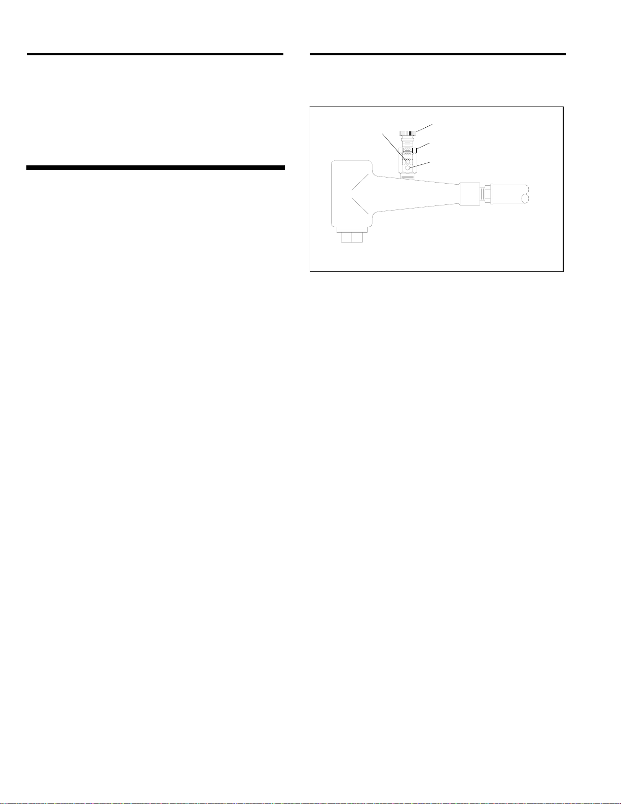
5.1. BNP Gun Assembly
5.1.1 Inspect the BNP gun for wear. Inspection and
replacement of the air jet cover before it wears through
will prolong the life of the jet.
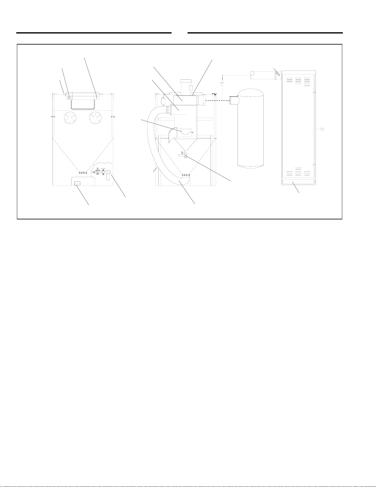
5.2 Dust Bag
5.2.1 The bag collects dust on its inner surface. A high
dust level in the cabinet indicates a dirty bag. Empty as
frequently as necessary to maintain visibility in the
cabinet, and before the weight of dust prevents full
inflation of the bag. A zipper opening is located in the
bottom of the bag for emptying. NOTE: Poor visibility
and frequent emptying of the bag could indicate the
need to upgrade to a dry filter dust collector.
5.3 Dry Filter Dust Collector
5.3.1 The dry filter uses tubular filters, which collect
dust on their inner surfaces. A shaker arm accessible
from the outside of the collector is used to shake dust
from the filters. Every two hours, turn off the exhauster
and shake the filters vigorously.
CAUTION
Do not shake the filters when the exhauster is
on, doing so will accelerate wear on the filters
around the shaker assembly, but not shake the
dust loose.
5.3.2 Empty the dust collector drawer regularly. Begin
by checking the drawer daily and adjust frequency based
on usage and breakdown rate of media. Dump the
contents into a suitable disposal container.
CAUTION
Do not open the dust drawer door while the
exhauster is on. The drawer chamber is under
positive pressure when the exhauster is on.
Opening the dust door while the exhauster is
operating or the paddle wheel rotating, will
allow dust to escape.
NOTE: Blast media is usually non-toxic, however, some
materials removed by the process may be toxic. Do not
use the INEX cabinet for blasting toxic materials.
Use cabinets with reverse pulse dust collectors and
HEPA filters for those applications.
5.4 View Window Cover Lens
5.4.1 Rapid frosting of the view window can be
avoided by directing ricocheting media away from the
window, and by installing a cover lens on the inside
surface of the window. Using cover lenses prolongs the
life of the view window.
5.4.2 To install a cover lens, remove the adhesive
backing and apply the lens to the clean, dry, inner
surface of the view window. When the cover lens
becomes pitted or frosted, peel it off and replace it.
5.5 Reclaimer Debris Screen
5.5.1 The screen is accessible through the reclaimer
door. With the exhauster off, remove the screen and
empty it daily or when loading media. Empty the screen
more often if part blasted causes excessive debris. Do
not operate the machine without the screen in place.
5.6 Air Filter
5.6.1 The cabinet is equipped with a manual drain air
filter. Drain the filter at least once a day, and more often
if water is present. Moist air inhibits the flow of media. If
moisture continues to be a problem, a dryer or after
cooler may be required in the air supply line.
5.7 Media Hose
5.7.1 To avoid unscheduled down-time, periodically
inspect the media hose for thin spots, by pinching it
every 6 to 12 inches. Replace the hose when it becomes
soft.

INEX SUCTION BLAST CABINET with 300 CFM RECLAIMER Page 9
© 2005 CLEMCO INDUSTRIES CORP. •www.clemcoindustries.com •Manual No. 21803 Rev. D 03/05
6.0 SERVICE MAINTENANCE
WARNING
Failure to wear approved respirators and eye
protection when servicing dust-laden areas of
the cabinet and dust collector, and when
emptying the dust bag or collector could result
in serious eye irritation and lung disease or
death. Toxicity and health risk vary with type of
media and dust generated by blasting. Identify
all material being removed by blasting, and
obtain a material safety data sheet for the blast
media.
6.1 Gloves
6.1.1 Special static-dissipating gloves are provided for
operator comfort. It will be necessary to change gloves
periodically as they wear. The first sign of deterioration
may be excessive static shocks.
6.1.2 Gloves are held in place by metal bands on the
inside of the cabinet. To replace, loosen the bands with
a screwdriver, replace the gloves, and tighten the bands.
6.2 Nozzle
6.2.1 Replace the nozzle when its diameter has
increased by 1/16", or when suction diminishes
noticeably. To change the nozzle, unscrew the holding
nut from the gun end, and pull the nozzle from the gun.
Inspect the nozzle O-ring and replace if worn or
damaged. Insert a new nozzle, placing the tapered end
toward the jet. Screw the holding nut onto the gun.
6.3 View Window Replacement
WARNING
Do not use plate glass for replacement view
windows. Plate glass shatters on impact and
could cause severe injury. Use only genuine
replacement parts.
6.3.1. Swing the light-shield up and tie it in place, as
shown in Figure 6.
6.3.2. Remove the filler strip by pulling it out of the
window molding, as shown if Figure 6.
Figure 6
6.3.3. Place an arm into a glove, and push the bottom
edge of the window out of the molding, as shown in
Figure 7, while supporting the top of the window with the
other hand.
Figure 7
6.3.4. Pull the window downward to remove the
window from the molding, as shown if Figure 8.
Figure 8

INEX SUCTION BLAST CABINET with 300 CFM RECLAIMER Page 10
© 2005 CLEMCO INDUSTRIES CORP. •www.clemcoindustries.com •Manual No. 21803 Rev. D 03/05
6.3.5. If the window molding needs replacing, replace it
in the same order as the old; the narrow channel fits
over the metal edge of the opening, as shown in Figure
9. The molding ends should meet in the middle of the
top, straight section of the opening. Molding should be
compressed so the ends are tightly sealed.
Figure 9
6.3.6. Spray silicone lubricant into the window channel
(wide channel) on the molding, and slide the window into
the channel, as shown in Figure 10. Place an arm into a
glove to support the top edge of the bottom side of the
window with one hand, while guiding the top edge into
the molding with the other.
Figure 10
6.3.7. Use a nylon window stick, Stock No. 22933, as
shown in Figure 11, and work the window channel lip
over the glass. When this is done, the window should be
entirely within the molding’s window channel.
6.3.8. Wipe, or spray the filler strip with silicone
lubricant to reduce friction. Thread about half of the strip
into the installation tool, Stock No. 12176.
Figure 11
6.3.9. Insert the end of the installation tool and filler
strip into the filler strip channel of the molding, about two
inches to the left of the window molding ends, as shown
in Figure 12. The rounded side of the filler strip faces up.
Figure 12
6.3.10. Feed the filler strip while pulling the tool through
the top of the channel, down the side and across the
bottom until that end of the strip is in place. Ref. Figure
13.
Filler Strip
Cabinet Wall
View Window Filler Strip channel
Rounded side up
Narrow Channel
Wide Channel

INEX SUCTION BLAST CABINET with 300 CFM RECLAIMER Page 11
© 2005 CLEMCO INDUSTRIES CORP. •www.clemcoindustries.com •Manual No. 21803 Rev. D 03/05
Figure 13
6.3.11. Repeat steps 6.3.9 and 6.3.10 on the other end
of the filler strip. Use the window stick to push the filler
strip into the molding at any spot the strip is not fully
seated. Place the light-shield in its normal position.
6.4 Dry Filter Tube Replacement, Figure 14
CAUTION
•Do not bend spring ends tight enough to
cause ends to kink.
•Do not use a sharp instrument to force
spring rings into the opening. This could
damage the filter and seriously impair the
function of the dust collector.
•Install one filter at a time. Check the seating
of the top and bottom spring rings, and that
tube is not twisted, before proceeding to the
next.
6.4.1 Replace damaged filters immediately. Remove
the old filters by pulling the spring rings off the bottom
and top tube plates. Working from the back to the front,
install one filter at a time. To install new filters, form the
end of the spring ringed tubular filter into a shallow "c"
shape, push the filter far enough into the hole of the top
plate to allow one spring ring to snap into place above
the tube plate and the other to snap into place below it.
See the illustration in Figure 14.
Figure 14
6.4.2 The tubular filter is held firmly by spring rings
above and below the perimeter of the hole in the top and
bottom tube plate. The filters fit tight to prevent dust
leakage. Force may be required by the installer. Check
for proper seating at both ends, and remove any twist in
the tube before proceeding to the next filter.
6.5 Dust Bag
6.5.1 Replace the bag at first sign of dust leak, or as
necessary to maintain visibility in the cabinet. If visibility
is poor, periodic washing may restore the porosity of the
cloth and increase ventilation through the cabinet.
6.6 Reclaimer Wearplate Replacement
6.6.1 Remove the reclaimer inlet adaptor and old
wearplate. The wearplate is held in place by screws
attached from the outside of the reclaimer.
6.6.2 Angle the new wearplate into the reclaimer inlet
until it is in position with the straight end at the reclaimer
inlet. Using a board or similar object as leverage, pry the
wearplate against the inner wall of the reclaimer and
install sheet metal screws to hold in place. Caulk any
gaps or voids around the wearplate to prevent rapid
wear in those areas.
Bottom Tube Plate
Top Tube Plate
Spring Ring
Spring Ring
One ring above tube plate
One ring below tube plate

INEX SUCTION BLAST CABINET with 300 CFM RECLAIMER Page 12
© 2005 CLEMCO INDUSTRIES CORP. •www.clemcoindustries.com •Manual No. 21803 Rev. D 03/05
7.0 TROUBLESHOOTING
WARNING
To avoid serious injury, observe the following
when troubleshooting.
•Turn off the air, and lock out and tag out the
air supply.
•If checking the controls requires air, always
enlist the aid of another person to:
Hold the blast gun securely.
Operate the foot pedal.
•Never bypass the foot pedal or wedge it in
the operating position.
•Never override the door interlock system.
7.1 Poor Visibility
7.1.1 Dirty filter bag or tube filters. Shake tube filters,
and empty dust drawer regularly.
7.1.2 Motor rotating backwards. The motor should
rotate as indicated by the arrow on the housing. If it does
not rotate in the proper direction, LOCK-OUT AND TAG-
OUT POWER and switch the motor leads as shown on
the motor plate. See Section 1.9.3.
7.1.3 Using friable media that rapidly breaks down, or
using media that is too fine or worn out.
7.1.4 Dust collector damper closed too far restricting
air movement in cabinet. Adjust static pressure per
Section 4.4.
7.1.5 Blocked air inlet duct. Blockage in the air intake
ducts restricts incoming air and reduces air movement in
the cabinet.
7.1.6 Hole worn in flex hose between cabinet hopper
and reclaimer inlet. Replace hose and route it with as
few bends as possible to prevent wear.
7.1.7 Reclaimer door open.
7.1.8 Obstruction in flex hose between the cabinet
hopper and reclaimer inlet.
7.1.9 Paddle wheel worn. Check wheel for wear.
7.2 Abnormally High Media Consumption
7.2.1 Door on reclaimer open, or improper fit or worn
door gasket. Air entering the reclaimer at this point will
cause media to be carried into the dust collector. DO
NOT operate unless all doors are closed.
7.2.2 Dust collector damper open too far. Adjust static
pressure per Section 4.4.
7.2.3 Media may be too fine or worn-out.
7.2.4 Using friable media that rapidly breaks down.
7.2.5 Nozzle pressure too high for the media, causing
media to break down.
7.2.6 Hole worn in reclaimer, or leak in reclaimer
seams. Check entire reclaimer for negative-pressure
leaks.
7.2.7 If using very fine media (200 mesh and finer),
the inlet baffle of the reclaimer may need to be removed.
Consult the factory before proceeding with this option.
7.2.8 Optional externally adjustable vortex cylinder out
of adjustment. See Section 4.5.
7.3 Reduction In Blast Cleaning Rate
7.3.1 Low media level reducing media flow. Check
and fill if low.
7.3.2 Incorrect metering valve adjustment. Adjust per
Section 4.3.
7.3.3 Reduced air pressure. This may be caused by a
malfunctioning regulator, a dirty filter element in the air
filter, partially closed air valve, leaking air line, or other
air tools in use.
7.3.4 Blockage in media line or gun. Blockage may
occur as a result of a missing debris screen, or incorrect
metering valve adjustment permitting heavy media flow.
See Section 4.3.
7.3.5 Worn gun parts such as nozzle or air jet. Inspect
and replace all worn parts.
7.3.6 Worn media hose. Check hose for leaks and soft
spots. Replace worn or damaged hose.
7.3.7 Air jet in gun out of adjustment. Check
adjustment per Section 4.2.
7.3.8 Moist media. Frequent bridges or blockage in
the area of the metering valve can be caused by
moisture. See Section 7.5.

INEX SUCTION BLAST CABINET with 300 CFM RECLAIMER Page 13
© 2005 CLEMCO INDUSTRIES CORP. •www.clemcoindustries.com •Manual No. 21803 Rev. D 03/05
7.4 Plugged Nozzle
7.4.1 A damaged or missing reclaimer screen will
allow large particles to pass and block the nozzle.
Replace or re-install as necessary.
7.4.2 Media mixture too rich. Adjust media/air mixture
per Section 4.3.
7.5 Media Bridging
7.5.1 Frequent bridging or blockage in the media
metering valve can be caused by damp media. Media
becomes damp by blasting parts that are slightly oily,
from moisture in the compressed air line, or from
absorption.
7.5.2 To avoid contaminating media from the
workpiece, all parts put into the cabinet should be clean
and dry. If parts are oily or greasy, degrease and dry
them prior to blasting.
7.5.3 Moist compressed air. This can be caused by a
faulty compressor that overheats, or pumps oil or
moisture into the air line, too long an air line permitting
moisture to condense on the inside, or from high
humidity. Drain the air filter and receiver tank regularly. If
the problem persists, it may be necessary to change
media more often, or install an aftercooler or air dryer.
7.5.4 Absorption. Some media tends to absorb
moisture from the air, especially fine-mesh media in high
humidity areas. Empty the media and store it in an
airtight container when cabinet is not in use.
7.5.5 A vibrator attached to the reclaimer cone or
media metering valve may help prevent bridging of fine-
mesh media.
7.6 Neither Media Nor Air Comes Out The Nozzle
When The Foot Pedal Is Pressed.
7.6.1 Door interlocks not engaging. Check adjustment
per Section 4.6.
7.6.2 Blocked or leaking control lines. Check all
urethane tubing for blockage or leaks.
7.6.3 Foot pedal valve malfunction. Check foot pedal
alignment, and inlet and outlet lines for pressure.
7.6.4 Check that lines are not reversed on the foot
pedal or pilot regulator. See schematic in Figure 21.
7.6.5 Pressure regulator may be turned down or off.
Check pressure on pilot regulator.
7.6.6 Make sure that the air compressor is on and air
supply valves are open.
7.6.7 Check the nozzle to see if it is plugged. See
Section 7.4.
7.7 Blasting Does Not Stop When The Foot Pedal
Is Released
7.7.1 Make sure that the 3-way valve in the foot pedal
exhausts air when the pedal is released. If it does not,
check the line for blockage, and check the switch for
defect.
7.8 Blockage In Media Hose
7.8.1 Media obstructions. Usually caused when the
media mixture is too rich. Adjust media/air mixture per
Section 4.3.
7.8.2 Wet or damp media. See Section 7.5.
7.9 Media Surge
7.9.1 Heavy media flow. Adjust per Section 4.3.
7.10 Poor Suction In Media Hose
7.10.1 Inadequate air supply. Check the tables in
Figures 2 and 3.
7.10.2 Air jet needs adjustment. Check adjustment per
Section 4.2.
7.10.3 Nozzle is worn. Replace if worn 1/16" or more.
7.10.4 Blockage in media hose or nozzle. See Section
7.4 and 7.8.
7.10.5 Wrong size combination of air jet and nozzle
See table in Figure 2.
7.10.6 Air jet sleeve extends past end of air jet. Cut the
sleeve to align with the air jet.
7.11 Blow-Back Through Media Hose
7.11.1 Blockage in nozzle. Remove the nozzle and
check blockage.

INEX SUCTION BLAST CABINET with 300 CFM RECLAIMER Page 14
© 2005 CLEMCO INDUSTRIES CORP. •www.clemcoindustries.com •Manual No. 21803 Rev. D 03/05
7.11.2 Air jet may be too large for nozzle. See table in
Figure 2.
7.12 Static Shocks
7.12.1 Cabinet and/or operator not grounded. Abrasive
blasting generates static electricity. The cabinet must be
grounded to prevent static buildup. See Section 2.4. If
shocks persist, the operator may be building up static.
Attach a small ground wire (such as a wrist strap), from
the operator to the cabinet.
7.12.2 Avoid holding parts off the grate. Static will
buildup in the part if not dissipated through the metal
cabinet.
7.13 Dust Leaking From Dust Collector
7.13.1 Check for damaged or loose filters.
7.13.2 Check for a faulty seal on the dust drawer.
7.13.3 Check that upper and lower tube sheets are
sealed on both sides, front, and rear.
8.0 ACCESSORIES AND REPLACEMENT
PARTS
8.1 Optional Accessories
Description Stock No.
Tungsten carbide nozzle
No. 5 ................................................................13118
No. 7 ................................................................12882
No. 8 ................................................................11942
Boron carbide nozzle
No. 5 ................................................................11935
No. 6 ................................................................11936
No. 7 ................................................................11937
No. 8 ................................................................12894
Wide spray nozzle
Tungsten carbide
No. 6 ..........................................................11947
Boron carbide
No. 6 ..........................................................11934
No. 8 ..........................................................11944
NOTE: Wide spray nozzles require the following
accessories:
Wide spray nozzle nut .....................................11916
Wide spray retaining ring .................................12038
Wide spray nozzle guard .................................12295
Hose, light lined flex, 4" ID for aggressive media
7 ft required ...............................................12466
Vortex cylinder assembly, externally adjustable for
exhauster mounted reclaimers. For use with fine-mesh
or lightweight media.
for 300 cfm reclaimer .......................................19059
Optional Extension Nozzles, Figure 15
Item Description Stock No.
1. 3" Straight extension nozzle
No. 5, 5/16" orifice .....................................11921
No. 6, 3/8" orifice .......................................11922
No. 7, 7/16" orifice .....................................11923
2. 6" Straight extension nozzle
No. 5, 5/16" orifice .....................................11927
No. 6, 3/8" orifice .......................................11928
No. 7, 7/16" orifice .....................................11929
3. 9" Straight extension nozzle
No. 5, 5/16" orifice .....................................11924
No. 6, 3/8" orifice .......................................11925
No. 7, 7/16" orifice .....................................11926
4. 4" Side angle extension nozzle, complete
5/16" orifice, includes item 7, 8 & 9 ...........21311
5. 6" Side angle extension nozzle, complete
5/16" orifice, includes item 7, 8 & 9 ...........12374
6. 9" Side angle extension nozzle, complete,
5/16" orifice, includes item 7, 8 & 9 ...........12373
7. Tip, side angle extension ..............................12173
8. Snap ring, side angle extension ...................12040
9. O-Ring, side angle extension .......................08977
Figure 15
4, 5, 6
9
7
Standard Nozzle
1, 2, 3
Note:
Leave the standard nozzle in
the gun, slip the nozzle
holding nut over the extension
nozzle, and tighten onto the
gun body
8

INEX SUCTION BLAST CABINET with 300 CFM RECLAIMER Page 15
© 2005 CLEMCO INDUSTRIES CORP. •www.clemcoindustries.com •Manual No. 21803 Rev. D 03/05
8.2 Cabinet Replacement Parts, Figure 16
Item Description Stock No.
1. Gasket, door, adhesive backed,
10 ft. per door, specify feet required .........00187
2. Light shield assembly with switch ................ 11346
3. Window glass, 12.5" x 19.5" ........................12212
4. Gasket, window, 6 ft. req.......................... 12435
5. Filler strip, window gasket, 6 ft. req.......... 12436
6. Cover lens, pkg. of 5 .................................... 06190
7. Grate, 3048 .................................................. 10761
8. Latch assembly, door ................................... 10908
9. Glove set ...................................................... 11215
10. Glove, left hand only .................................... 12710
11. Glove, right hand only .................................. 12711
12. Clamp, glove ................................................ 11576
13. Hose, 4" ID flex
7 ft required ............................................... 12447
14. Clamp, flex hose
for 4" hose ................................................. 11577
15. Grommet, media/air hose ............................11798
16. Actuator, door interlock ................................ 19152
17. Over-travel stop, door interlock ....................20004
18. Detent sleeve, door interlock .......................15042
19. Air valve, 3 way, door interlock ....................12202
20. Regulator, 1/8" NPT pilot .............................12715
21. Gauge, pressure .......................................... 11831
22. Foot pedal assembly, less tubing ................20483
Figure 16
6
14
9, 10, 11
15
22
16
42
1
8
5 3 20 21 17, 18, 19
7
13
12

INEX SUCTION BLAST CABINET with 300 CFM RECLAIMER Page 16
© 2005 CLEMCO INDUSTRIES CORP. •www.clemcoindustries.com •Manual No. 21803 Rev. D 03/05
8.3 BNP Gun and Feed Assembly, Figure 17
Item Description Stock No.
(-) BNP Gun assemblies less nozzle, includes
items 1 (brass) through 7
No. 4 Gun ..................................................12301
No. 5 Gun ..................................................12302
No. 6 Gun ..................................................12303
No. 7 Gun ..................................................12304
No. 8 Gun ..................................................12305
1. Nut, nozzle holding
Standard, knurled brass ............................11914
Urethane covered ......................................11574
2. O-Ring ..........................................................08975
3. Gun body ......................................................11802
4. Lock nut, air jet .............................................11913
5. Rubber sleeve ..............................................12097
6. Air jet assembly w/ Item 5
No. 4 ..........................................................12342
No. 5 ..........................................................12343
No. 6 ..........................................................12344
No. 7 ..........................................................12345
No. 8 ..........................................................12346
7. Fitting, hose, 3/8" NPT x 1/2" barb ...............06369
8. Hose end, 1/2" barb x 1/2" fem. swivel .........15002
9. Nozzle, ceramic
No. 5 ..........................................................11930
No. 6 ..........................................................11931
No. 7 ..........................................................11932
Nozzle, boron carbide
No. 5 ..........................................................11935
No. 6 ..........................................................11936
No. 7 ..........................................................11937
No. 8 ..........................................................12894
Nozzle, tungsten carbide
No. 5 ..........................................................13118
No. 7 ..........................................................12882
No. 8 ..........................................................11942
10. Hose, 1/2" air, six feet required ....................12472
11. Hose, media, clear urethane,
six feet required .........................................12476
12. Wide spray nozzle
Tungsten carbide, No. 6 ............................11947
Boron carbide
No. 6 .......................................................11934
No. 8 .......................................................11944
13. Wide spray nozzle nut
Knurled brass ............................................11916
Urethane covered ......................................12906
14. Wide spray retaining ring ..............................12038
15. Wide spray nozzle guard ..............................12295
16. Orifice adjusting tool .....................................19041
Figure 17
1
9
2
3
4
5
6
8
11 7
10
1
13
16
14
13
12
15

INEX SUCTION BLAST CABINET with 300 CFM RECLAIMER Page 17
© 2005 CLEMCO INDUSTRIES CORP. •www.clemcoindustries.com •Manual No. 21803 Rev. D 03/05
8.4 Foot Pedal Assembly, Figure 18
Item Description Stock No.
(-) Foot pedal assembly, less tubing ................ 20483
1. Top, foot pedal ............................................. 20017
2. Base, foot pedal ........................................... 19991
3. Valve, 10-32, 3 way n/c ............................... 20026
4. Drive pin, grooved ........................................ 20109
5. Screw, sh 1/4 NF x 3/4" ...............................03086
6. Screw, 10-32 x 1/2" fh .................................. 19571
7. Adaptor, 10-32 thrd. x 1/8 barb .................... 11731
8. Spring, 1-1/4" x 3-1/2" ..................................20121
9. Screw, 8-32 x 3/8" thread cutting ................. 11389
10. Bumper, rubber (feet) ................................... 21522
Figure 18
8.5 Metering valve assembly, Figure 19
Item Description Stock No.
(-) Metering valve assembly ............................. 12417
(-) Metering stem assembly (items 1, 2, & 3) ...23889
1. Stem, metering adjusting ............................. 23097
2. Screw, adjusting ........................................... 23098
3. Nut, adjusting stem lock ............................... 23099
4. Body, metering valve ................................... 11532
5. Fitting, hose, 3/8" NPT x 1/2" barb .............. 06369
6. Plug, metering valve .................................... 12011
Figure 19
8.6 Light Shield Assembly, Figure 20
Item Description Stock No.
(-) Light shield assembly with switch ................ 11346
1. Ballast .......................................................... 11553
2. Lamp holder ................................................. 11843
3. Starter holder ............................................... 12163
4. Starter .......................................................... 12156
5. Lamp, 15 watt .............................................. 11872
6. Regulator, 1/8" pilot ..................................... 12715
7. Connector, poly straight ............................... 02929
8. Gauge, pressure .......................................... 11831
9. Base plate, light shield ................................. 11561
10. Trim edge, 2 ft. required .............................. 18460
11. Fitting, 1/8" male NPT x 1/8" barb ............... 11732
12. Fitting, elbow, 1/8" male NPT x 1/8" barb .... 11733
13. Fitting, 10-32 x 1/8" barb ............................. 11731
14. Tubing, 1/8" urethane, 1 ft. min. order ......... 12475
15. Grommet, rubber 1/4" ID x 1/2" OD ............. 12762
16. Switch, on-off ............................................... 12127
Figure 20
12
3
4
5
67
1
14
2
9
3
10
4
11
5
12
6
8
7
15
8
13
9
10
1
2
4
5
6
16
3

INEX SUCTION BLAST CABINET with 300 CFM RECLAIMER Page 18
© 2005 CLEMCO INDUSTRIES CORP. •www.clemcoindustries.com •Manual No. 21803 Rev. D 03/05
8.7 Cabinet Plumbing Assembly, Figure 21
Item Description Stock No.
1. Valve, 3 way .................................................12202
2. Adaptor, 1/8" NPT x 1/8" barb ......................11732
3. Tubing, 1/8" urethane, specify ft. required ...12475
4. Tubing, twin urethane, specify ft. required ...19577
5. Foot pedal assembly, less tubing .................20483
6. Fitting, 1/8" NPT elbow x 1/8" barb ..............11733
7. Bushing 1/2"x 1/8" NPT ................................11350
8. Bushing 1/4"x 1/8" NPT ................................02010
9. Bracket, mounting .........................................19231
10. Filter, 1/2" manual drain ...............................01308
11. Adaptor, 1/2" NPT x 1/2" flare ......................11351
12. Hose end, 1/2" barb x 1/2" female swivel .....15002
13. Hose end, 1/2" barb x 3/8" male NPT. .........06369
14. Blow-off nozzle .............................................13116
15. Air hose, 1/2", specify ft. required ................12472
16. Gun assembly, BNP No. 5 ...........................12302
17. Hose, clear urethane, specify ft. required ....12476
18. Regulator, 1/2" pilot operated .......................11345
19. Regulator, 1/8" pilot ......................................12715
20. Gauge, pressure ...........................................11831
21. Metering valve assembly ..............................12417
22. Fitting, 10-32 x 1/8" barb ..............................11731
Figure 21
1
2
1
3
3
6
19 20
4 5
16
17
14
15
15 13
8
11
12
18
11
12
10
9 7
13
Unregulated Air
Regulated Air
To
″
IN
″
on valve
To
″
OUT
″
on valve
2(outlet)
3
2(inlet)
2 (outlet)
2(inlet)
2
Compressed Air Inlet
12
21
22
2

INEX SUCTION BLAST CABINET with 300 CFM RECLAIMER Page 19
© 2005 CLEMCO INDUSTRIES CORP. •www.clemcoindustries.com •Manual No. 21803 Rev. D 03/05
8.8 Reclaimer, Figure 22
Item Description Stock No.
(-) Reclaimer assembly, 300 cfm,
complete, w/ exhauster ............................. 12402
less exhauster assembly ..........................12403
1. Motor, exhauster, 1/2 HP, 115/230, 1-PH ...12308
2. Plate, motor mount, 300 cfm ........................12003
3. Housing, exhauster, 300 cfm .......................12273
4. Gasket, 5/16" x 1" adhesive backed,
4 ft. required for each location .................. 00187
5. Paddle wheel, 300 cfm ............................... 12333
6. Inlet pipe adaptor
300 cfm, 4" ................................................ 12365
7. Gasket, inlet adaptor
300 cfm ..................................................... 11746
8. Wearplate
300 cfm ..................................................... 14060
9. Clamp, hose, 4-1/2"......................................11577
10. Screen assembly ......................................... 21265
11. Gasket, door ................................................ 11745
12. Hose, 4" ID flex, 7 feet required ................... 12447
13. Spring latch assembly .................................. 12263
14. Vortex cylinder assembly, adjustable,
for exhauster mounted reclaimer (optional)
300 cfm ..................................................... 19059
Figure 22
1
2
3
5
12
9 6 7
4
4
14
8
13
11 10 Parts rotated for clarity
Table of contents
Other Zero Industrial Equipment manuals
Popular Industrial Equipment manuals by other brands

Daikin
Daikin DRC installation instructions

HYDAC FILTER SYSTEMS
HYDAC FILTER SYSTEMS LVU-CD-10 Operating and maintenance instructions

ABB
ABB HT581629 Operation manual

Graco
Graco ProMix PD2K Repair parts manual

Eaton
Eaton DA1-34370FB-B20C Instruction leaflet

Bühler technologies
Bühler technologies AGF-VA-350 manual