Tormach Slant-PRO 15L User manual

Quesons or comments?
Please email us: [email protected]
All rights reserved.
UM10225_15L_Slant-PRO_Manual_0920A
Document Part Number: 34397
©2020 Tormach Inc.
Tormach®15L Slant-PRO
Operator’s Manual
™
IMPORTANT! Read all safety precauons and instrucons thoroughly before aempng
15L Slant-PRO installaon, operaon, or maintenance.
Chapter 1 2UM10225_15L_Slant-PRO_Manual_0920A
Preface
SAVE THESE INSTRUCTIONS!
This manual contains important safety warnings and operang instrucons for the 15L Slant-PRO
lathe. Refer to these instrucons before aempng installaon, operaon or maintenance. Keep
these instrucons together with your 15L Slant-PRO lathe, so they are readily accessible. Any
updated versions of this manual are available at www.tormach.com/documents
Safety Precautions
Failure to read and follow these safety warnings and operang instrucons may result in voided
warranty, property damage, serious injury or death.
Symbol Description Example
WARNING! Indicates a hazard which, if not
avoided, could result in death or serious
injury.
WARNING! Ejecon Hazard: Tools and work
pieces must be clamped properly. Failure to do so
could result in death and/or serious injury.
CAUTION! Indicates a hazard which, if not
avoided, could result in injury or machine
damage.
CAUTION! Be sure to wear gloves when uncrang
lathe. Failure to do so could result in serious injury.
IMPORTANT! Addresses pracces not related to personal
injury.
IMPORTANT! Tighten the drawbar so the collet
holds the tool holder securely in posion.
NOTE: Indicates addional informaon,
claricaon, or helpful hints.
NOTE: For further informaon on automac oiler
troubleshoong, refer to the operator manual.
Machine Safety
Any machine tool is potenally dangerous. Computer-controlled machines are potenally more
dangerous than manual machines because, for example, a controller is quite prepared to plunge a
turning tool at 60 inches per minute into a D1-4 chuck face spinning at 2500 RPM.
The Tormach lathe can deliver sucient force to break tools, to crush bones, and to tear esh.
If loose hair, clothing, gloves, or jewelry gets caught by a rotang workpiece the results can be
disastrous.
This manual tries to give you guidance on safety precauons and techniques, but because the
details of each work area or other local condions dier, we can accept no responsibility for the
performance of the machine or any damage or injury caused by its use. It is your responsibility
to ensure that you understand the implicaons of what you are doing and to comply with any
legislaon and codes of pracce applicable to your country or state.

Chapter 1
3
UM10225_15L_Slant-PRO_Manual_0920A
Preface
Machine Safety
Safe operaon of the machine depends on its proper use and the precauons taken by the operator.
Read and understand this manual prior to use. Only trained personnel – with a clear and thorough
understanding of its operaon and safety requirements – should operate this machine.
General Safety:
• Wear OSHA-approved safety glasses, safety shoes, and ear protecon.
• Remove loose-ng clothing, neckes, gloves, and jewelry.
• Tie up long hair or secure under a hat.
• Never operate a machine aer consuming alcohol or taking medicaon.
• Keep work area well lit and deploy addional lighng, if needed.
Operaonal Safety
• Understand CNC lathes are automacally controlled and may start at any me.
• Do not leave machine unaended during operaon.
• Always power o machine when not in use.
• Never operate with the door or chuck guard open; never bypass safety switches.
• Do not operate without knowing the funcon of every control key, buon, knob or handle.
Refer to the operator manual or contact Tormach if any funcon is not understood.
• Do not extend unsupported bar stock past the le end of the spindle bore.
• Do not operate with an unbalanced workpiece or spindle xtures.
• Remove all tools (wrenches, chuck keys, etc.) from the spindle and machine surfaces before
starng operaons; loose items can become dangerous projecles.
• Use adequate work clamping; loose workpieces can become projecles.
• Be aware of workpiece cutos that could be cut free during operaons and become dangerous
projecles.
• Protect your hands. Stop machine spindle and ensure lathe moon has stopped before:
- Reaching into any part of the machine moon envelope
- Changing tools or parts
- Clearing away chips, oil, or coolant; always use a chip scraper or brush
- Making an adjustment to the workpiece, xture, or coolant nozzle
- Taking measurements
• Keep work area clear of cluer as machine moon can occur when keys are accidentally
pressed or objects fall on keyboard, resulng in unexpected moon.

Chapter 1 4UM10225_15L_Slant-PRO_Manual_0920A
Preface
• Avoid geng pinched in places where the table, saddle, or spindle head create pinch points
while in moon.
• Always use proper feeds, speeds, and depths of cut to prevent tool breakage.
• Chips and dust from certain materials (e.g., magnesium) can be ammable. Fine dust from
normally non-ammable materials can be ammable or even explosive.
• Chips and dust from certain materials can be toxic. Vapors from certain overheated materials
can be toxic. Always check a Material Safety Data Sheet (MSDS) of suspect materials. Refuse
machining work requests of unknown materials.
• If in any doubt, seek guidance from a professionally qualied expert rather than risk injury to
yourself or to others.
• Use adequate safeguarding around the operang envelope.
It is the responsibility of the operator/employer to provide and ensure point of operaon safeguarding
per the following:
• OSHA 1910.212 - General Requirements for All Machines
• ANSI B11.5-1984 (R1994) Lathes
• ANSI B11.22-2002 Safety Requirements for Turning Centers and Automac Numerically
Controlled Turning Machines
• ANSI B11.TR3-2000 Risk Assessment and Risk Reducon - A Guideline to Esmate, Evaluate,
and Reduce Risks Associated with Machine Tools.
Electrical Safety
WARNING! Electrical Shock Hazard: Be sure to power o machine before making any electrical
modicaons. Failure to do so may result in serious injury or death.
Never operate the machine tool with the cabinet door open. Never allow a coolant pump to operate
with the cabinet door open. Do not allow the coolant system to ow coolant directly at the cabinet
door seal or on the operator console controls. Neither the cabinet door seal nor the electrical
controls are sealed against liquids.
Dual Power Input: The Tormach 15L Slant-PRO has two electrical power inputs. The primary supply is
200 to 250 VAC single phase and is used for all axis and spindle moon. This should be on a dedicated
circuit of at least 20A. Either of the 15L Slant-PRO’s two electrical power inputs can provide lethal
electrical shocks. Both power inputs should be unplugged before working in the electrical cabinet.
Electrical Service: Certain service and troubleshoong operaons require access to the electrical
cabinet while the electrical power is on. Only qualied electrical technicians should perform such
operaons.
Retained Electrical Power: Electronic devices within the electrical cabinet may retain dangerous
voltage levels aer the power has been removed.

Chapter 1
5
UM10225_15L_Slant-PRO_Manual_0920A
Preface
Warranty
Limited Warranty Coverage
Each Tormach (the “Manufacturer”) 15L Slant-PRO machine (“Machine”) and its components
(“Components”) — except those listed below under limits and exclusions — is warranted against
defects in material and workmanship for a period of 12 months from the date of delivery. The
foregoing is a limited warranty and it is the only warranty by the manufacturer. Manufacturer
disclaims all other warranes, express or implied, including but not limited to all warranes of
merchantability and tness for a parcular purpose.
Repair or Replacement Only
Manufacturer’s liability under this agreement shall be limited to repairing or replacing, at the
discreon of manufacturer, parts or components. Shipment for items replaced under warranty is
free, but the shipment method is at the discreon of Tormach. In general delivery is via UPS ground
service for domesc customers or the U.S. Postal Service (USPS) for internaonal customers. If
overnight or express delivery is requested, addional fees will apply.
Direct sales and phone support are part of the equaon that allows us to provide high value at low
cost. You must be comfortable with general electrical and mechanical repair concepts, including
appropriate safety procedures, before working on your machine. If you do not have the required
skills you need to nd someone locally to assist you. We do not have factory technicians to send to
your facility.
Limits and Exclusions of Warranty
Except as provided above, buyer agrees that all warranes express or implied, as to any maer
whatsoever, including but not limited to warranes of merchantability and tness for a parcular
purpose are excluded. Components subject to wear during normal use and over me such as paint,
labels/decals, nish/condion, seals, ex cabling, spindle, etc., are excluded from this warranty.
Tormach-specied maintenance procedures must be adhered to in order to maintain this warranty.
This warranty is void if the machine is subjected to mishandling, misuse, neglect, accident, improper
installaon, improper maintenance, or improper operaon or applicaon, or if the machine was
improperly repaired or serviced. Warranty of general machine tolerances is void if the machine is
disassembled or altered by customer. Without liming the generality of any of the exclusions or
limitaons described in other paragraphs, manufacturer’s warranty does not include any warranty
that the machine or components will meet buyer’s producon specicaons or other requirements
or that operaon of the machine and/or components is uninterrupted or error-free. Manufacturer
assumes no responsibility with respect to the use of the Machine and Components by Buyer, and
manufacturer shall not incur any liability to Buyer for any failure in design, producon, operaon,
performance or otherwise of the Machine or components other than repair or replacement of
same as set forth in the Limited Warranty above. Manufacturer is not responsible for any damage
to parts, machines, business premises or other property of Buyer, or for any other incidental or
consequenal damages that may be caused by a malfuncon of the machine or components.

Chapter 1 6UM10225_15L_Slant-PRO_Manual_0920A
Preface
Limitaon of Liability and Damages
Manufacturer is not liable to Buyer, or any customer of buyer for loss of prots, lost data, lost
products, loss of revenue, loss of use, cost of down me, business good will, or any other incidental
or consequenal damage, whether in an acon in contract or tort, arising out of or related to the
machine or components, other products or services provided by manufacturer or seller, or the
failure of parts or products made by using the machine or components, even if manufacturer or
seller has been advised of the possibility of such damages.
Manufacturer’s liability for damages for any cause whatsoever shall be limited to repair or
replacement, at the discreon of manufacturer, of the defecve parts, components or machine.
Buyer has accepted this restricon on its right to recover incidental or consequenal damages as part
of its bargain with Seller. Buyer realizes and acknowledges that the price of the equipment would
be higher if Seller or Manufacturer were required to be responsible for incidental or consequenal
damages, or punive damages. This warranty supersedes any and all other agreements, either oral
or in wring, between the pares hereto with respect to the warranes, limitaons of liability and/or
damages regarding the Machine or Components, and contains all of the covenants and agreements
between the pares with respect to such warranes, liability limitaons and/or damages. Each party
to this warranty acknowledges that no representaons, inducements, promises, or agreements,
orally or otherwise, have been made by any party, or anyone acng on behalf of any party, which are
not embodied herein regarding such warranes, liability limitaons and/or damages, and that any
agreement, statement, or promise not contained in this warranty shall be not be valid or binding
regarding such warranes, liability limitaons and damages.
Transferability
This warranty is transferable from the original end-user to another party if the machine is sold via
private sale before the end of the warranty period. Should you have a problem with your machine,
please consult your operator’s manual rst. If this does not resolve the problem, contact Tormach
through our Web site at www.tormach.com or call (608) 849-8381.
Extended Warranty
An extended warranty (PN 34381) is available for purchase at www.tormach.com or by calling (608)
849-8381.

Chapter 1
7
UM10225_15L_Slant-PRO_Manual_0920A
Preface
Intended Use
The Tormach 15L Slant-PRO is intended for use as a general purpose CNC lathe. The intended
use includes cung convenonal non-abrasive materials such as mild or alloy steels, aluminum,
plascs, and similar materials. Applicaons for the equipment or modicaons of the equipment
outside of the Intended Use Statement are supported through consulng engineering, not through
our free support policy. There are no limits to the applicaons that Tormach products can be used
for or to the modicaons that can be applied to the Tormach machinery. Tormach designs use
standard industrial components and incorporate the principles of Open Architecture specically
to allow and promote these variaons. With Open Architecture controls, industrial engineers will
nd Tormach products cost eecve to incorporate into larger manufacturing systems. All of the
technical informaon and insight required to support these variaons from the intended use cannot
possibly be foreseen. If the extensive documentaon provided does not supply all the informaon
you need, we can provide addional informaon and engineering support required for your project
on a consulng engineering basis. Consulng engineering is done by electrical and mechanical
engineers and billed at current hourly rates.
As you might expect, all warranes for Tormach equipment are voided through modicaon to the
equipment or use outside of the Intended Use. Individuals or companies involved with modifying
the equipment or applying the products assume all consequent liability.
Nomenclature
This manual uses the following typographical nomenclature
Soware Control Refers to a Soware Control e.g., an on-screen buon
Hardware Control Refers to a buon or switch on the lathe’s Operator Panel
G-code (e.g., G01X34.8) Used to show G-code programs
Key name (e.g., Enter)Tells you to press the indicated key
Buon name (e.g., Stop) Tells you to press the indicated buon

Chapter 1 8UM10225_15L_Slant-PRO_Manual_0920A
Preface
Table of Contents
1. Overview 18
1.1 Specicaons 19
2. Installaon 20
2.1 Lathe Prep and Setup 20
2.1.1 Locaon 20
2.1.2 Electrical Requirements 20
2.1.2.1 Primary 20
2.1.2.2 Secondary 20
2.1.2.3 Electrical Noise 20
2.1.2.4 Grounding 21
2.1.2.5 Ground Fault Interrupter (GFI) Use 21
2.2 Receiving, Uncrang, and Inial Inspecon 21
2.2.1 Moving the Crate 21
2.2.2 Uncrang 21
2.2.3 Shipping Damage or Shortages 21
2.2.4 Remove Lathe from Pallet 22
2.2.4.1 Lathe Li Kit 22
2.3 Basic Installaon Procedure 22
2.3.1 Aach Lathe Feet 22
2.3.2 Install PathPilot Controller 24
2.4 Installaon of Add-ons 25
2.4.1 Turret and Tailstock 25
2.4.2 Enclosure 25
2.4.3 Machine Arm 25
2.4.4 Oiler 26
2.4.4.1 Manual Oiler (oponal) 26

Chapter 1
9
UM10225_15L_Slant-PRO_Manual_0920A
Preface
2.5 Controller Customizaon 28
3. Operaon 29
3.1 Power O/Power On Procedure 29
3.2 Conrm Spindle Direcon 29
3.3 Lathe Axes Denion 31
3.4 Workholding 31
3.4.1 5C Collet Conguraon (Maximum Speed Rang: 3500 RPM) 31
3.4.2 D1-4 Chuck Conguraon (Maximum Speed Rang: 2500 RPM) 31
3.5 Tooling 32
3.5.1 Quick Change Tool Post (QCTP) 32
3.5.2 8-posion Turret 32
3.5.3 Gang Tooling 32
3.6 Front Tool Post and Rear Tool Post Locaons 33
3.7 Right-handed and Le-handed Tools 33
3.8 Chuck Guard and Full Enclosure 34
4. Intro to PathPilot 35
4.1 Making Your First Part 35
4.1.1 Reference the Lathe 35
4.1.2 Prepare the Workpiece 36
4.1.3 Prepare the Tools 36
4.1.4 Understand Machine Posion, Work Osets, and Tool Osets 37
4.1.5 Set the Length Units 37
4.1.5.1 Programming in Inches 37
4.1.5.2 Programming in Millimeters 37
4.1.6 Touch O the Workpiece to Set the Work Osets 38
4.1.6.1 Seng the Z Work Oset 38
4.1.6.2 Seng the X Work Oset 39

Chapter 1 10 UM10225_15L_Slant-PRO_Manual_0920A
Preface
4.1.7 Set the Tool Geometry Osets 39
4.1.7.1 Seng Tool 1 39
4.1.7.2 Touching O the Parng Tool 42
4.1.8 Write the G-code 43
4.1.8.1 Operaon 1 44
4.1.8.2 Operaon 2 46
4.1.8.3 Operaon 3 47
4.1.8.4 Operaon 4 48
4.1.8.5 Operaon 5 49
4.1.8.6 Run the Completed G-code Program 50
5. PathPilot Interface 51
5.1 Overall Layout 51
5.2 Persistent Controls 52
5.2.1 Program Control Group 52
5.2.2 Posion Status Group 54
5.2.3 Manual Control Group 56
5.2.3.1 Spindle Controls 57
5.2.3.2 Tool Label, Collet Open/Closed, G30 Controls, Ref Axes Buons 57
5.3 Keyboard Shortcuts 58
5.4 Main Tab 58
5.4.1 Selecng a Recent G-code Program File 59
5.4.2 Working in the G-code Window 59
5.4.2.1 Seng a New Start Line 59
5.4.2.2 Expanding the G-code Window 60
5.4.3 Manually Entering Commands 60
5.4.3.1 Searching in the Code 60
5.4.4 Working in the Tool Path Window 61

Chapter 1
11
UM10225_15L_Slant-PRO_Manual_0920A
Preface
5.4.4.1 Changing the View of the Tool Path Window 61
5.5 File Tab 62
5.5.1 Managing Files 62
5.5.1.1 Transferring Files or Folders from a USB Drive 62
5.5.2 Loading G-code 63
5.5.3 Eding G-code 63
5.5.3.1 Eding G-code with a Text Editor 63
5.5.3.2 Eding G-code with Conversaonal Programming 63
5.6 Sengs Tab 65
5.6.1 Selecng the Tool Changer Type 65
5.6.2 Enabling Feeds and Speeds Suggesons in Conversaonal Programming 66
5.7 Osets Tab 66
5.7.1 Tool Touch Tab 67
5.7.1.1 Touch X (Dia.) 67
5.7.1.2 Touch Z 68
5.7.2 Osets Table Tab 69
5.7.2.1 Creang Tool Descripons 69
5.7.3 Tool Oset Informaon Backup 72
5.8 Conversaonal Screens 73
5.8.1 Overview 73
5.8.2 Using Feeds and Speeds Suggesons 76
5.8.2.1 Adjusng DRO Values 77
5.8.2.2 Refreshing DRO Values 77
5.8.3 OD Turn Tab 78
5.8.4 ID Turn Tab 80
5.8.5 Prole Tab 82
5.8.6 Face Tab 88

Chapter 1 12 UM10225_15L_Slant-PRO_Manual_0920A
Preface
5.8.7 Chamfer and Radius Tab 90
5.8.8 Groove and Part Tab 93
5.8.9 Drill and Tap Tab 96
5.8.10 Thread Tab 98
5.9 Status Tab 101
6. Programming 103
6.1 Denions 103
6.2 Tool File 107
6.3 Part-programs Language 107
6.3.1 Overview 107
6.3.2 Parameters 108
6.3.3 Coordinate Systems 108
6.3.4 Formang G-code Lines (Block) 108
6.3.5 Line Number 109
6.3.6 Subroune Labels 109
6.3.7 Word 109
6.3.8 Number 109
6.3.9 Comments and Messages 110
6.3.10 Item Repeats 111
6.3.11 Item Order 113
6.3.12 Commands and Machine Modes 113
6.4 Modal Groups 113
6.5 G-codes 114
6.5.1 Rapid Linear Moon – G00 116
6.5.2 Linear Moon at Feed Rate – G01 117
6.5.3 Arc at Feed Rate – G02, G03 117
6.5.3.1 Radius Format Arc 117

Chapter 1
13
UM10225_15L_Slant-PRO_Manual_0920A
Preface
6.5.3.2 Center Format Arc 117
6.5.4 Dwell – G04 118
6.5.5 Lathe Diameter Mode – G07 118
6.5.6 Set Osets – G10 118
6.5.7 Set Tool Table – G10 L1 118
6.5.8 Set Coordinate System – G10 L2 119
6.5.9 Set Tool Table – G10 L10 119
6.5.10 Set Tool Table – G10 L11 120
6.5.11 Set Coordinate System – G10 L20 120
6.5.12 Plane Selecon – G17, G18, and G19 120
6.5.13 Length Units – G20 and G21 120
6.5.14 Return to Pre-dened Posion – G28, G28.1 121
6.5.15 Return to Pre-dened Posion – G30, G30.1 121
6.5.16 Spindle Synchronized Moon – G33 121
6.5.17 Rigid Tapping – G33.1 123
6.5.18 Compensaon O – G40 124
6.5.19 Cuer Compensaon – G41, G42 124
6.5.20 Dynamic Cuer Compensaon – G41.1, G42.1 124
6.5.21 Move in Absolute Coordinates – G53 125
6.5.22 Select Work Oset Coordinate System – G54 to G59 and G59 P~ 125
6.5.23 Set Path Control Mode – G61, G61.1 126
6.5.24 Set Blended Path Control Mode – G64 126
6.5.25 Threading Cycle – G76 126
6.5.25.1 Oponal Sengs 127
6.5.26 Tapping Cycle – G84 128
6.5.27 Distance Mode – G90, G91 129
6.5.28 Arc Distance Mode – G90.1, G91.1 129

Chapter 1 14 UM10225_15L_Slant-PRO_Manual_0920A
Preface
6.5.29 G92 Osets – G92, G92.1, G92.2, and G92.3 129
6.5.30 Feed Rate Mode – G93, G94, and G95 130
6.5.31 Spindle Control Mode – G96, G97 131
6.6 Built-in M-codes 132
6.6.1 Program Stop and Program End – M00, M01, M02, and M30 132
6.6.2 Spindle Control – M03, M04, and M05 133
6.6.3 Coolant Control – M07, M08, and M09 133
6.6.4 Automac Collet Closer Control – M10 and M11 133
6.6.5 Override Control – M48, M49 133
6.6.6 Feed Override Control – M50 133
6.6.7 Spindle Speed Override Control – M51 133
6.6.8 Set Current Tool Number – M61 134
6.6.9 Call Subroune – M98 134
6.6.10 Return from Subroune – M99 134
6.7 Other Input Codes 134
6.7.1 Feed Rate – F 134
6.7.2 Spindle Speed – S 135
6.7.3 Change Tool – T 135
6.8 Repeated Items 136
6.9 Order of Execuon 136
6.10 Error Handling 137
6.11 Parameters and Expressions 138
6.11.1 Parameters 138
6.11.2 Expressions 142
6.12 O-codes 143
7. Maintenance 149
7.1 Lathe Maintenance Schedule 149

Chapter 1
15
UM10225_15L_Slant-PRO_Manual_0920A
Preface
7.2 Understanding Machine Design 150
7.2.1 Machine Sness 150
7.2.2 Backlash, Fricon, and Lost Moon 150
7.2.3 Factors Combine 151
7.2.4 Adjusng Geometry 151
7.2.5 Achieving Accuracy in Machining 151
7.2.6 Rust Prevenon 151
7.3 Gibs, Dovetail Slideways, and Lubricaon 152
7.3.1 Gib Adjustment Procedure 153
8. Troubleshoong 155
8.1 Troubleshoong Basics 155
8.2 Tips and Tools for Troubleshoong (equipment and procedures) 155
8.2.1 Safety 155
8.2.2 Tips on Controller Diagnosis 156
8.2.3 Troubleshoong Tools 156
8.2.4 Using Digital Mulmeter for Electrical Tests 156
8.2.4.1 Measuring DC Voltage 157
8.2.4.2 Measuring AC Voltage 157
8.2.4.3 Measuring Resistance 157
8.2.5 Contacng Technical Support 157
8.3 Frequently Found Problems 158
8.3.1 Loose Wires 158
8.3.2 Wire Hairs 158
8.3.3 Poor Cable Connecons 158
8.3.4 Controller Restart Required 159
8.4 Review of Subsystems 159
8.4.1 Power Distribuon Subsystem 159

Chapter 1 16 UM10225_15L_Slant-PRO_Manual_0920A
Preface
8.4.1.1 Overview 159
8.4.1.2 Details of the Power Distribuon Subsystem 159
8.4.2 Control Power Subsystem 161
8.4.2.1 Overview 161
8.4.2.2 Details of the Control Power Subsystem 161
8.4.3 Controller Communicaon Subsystem 163
8.4.3.1 Overview 163
8.4.3.2 Details of the Controller Communicaon Subsystem 163
8.4.4 Axis Drive Subsystem 163
8.4.4.1 Overview 163
8.4.4.2 Details of the Axis Drive Subsystem 164
8.4.5 Spindle Drive Subsystem 166
8.4.5.1 Overview 166
8.4.5.2 Details of the Spindle Drive Subsystem 166
8.4.5.3 Spindle Direcon 168
8.4.6 Home Switches 169
8.5 Troubleshoong Subsystems 170
8.5.1 Power Distribuon Subsystem 171
8.5.2 Controller Communicaons Subsystem 172
8.5.3 Axis Drivers Subsystem 172
8.5.4 Spindle Drive Subsystem 175
9. Diagrams and Parts Lists 178
9.1 Base Assembly (exploded view) 178
9.2 Lathe Bed Z-axis Assembly (exploded view) 180
9.3 Lathe Cross Slide Assembly (exploded view) 182
9.4 Lathe Headstock Assembly (exploded view) 184
9.5 Lathe Cabinet Hardware (exploded view) 186

Chapter 1 18 UM10225_15L_Slant-PRO_Manual_0920A
Overview
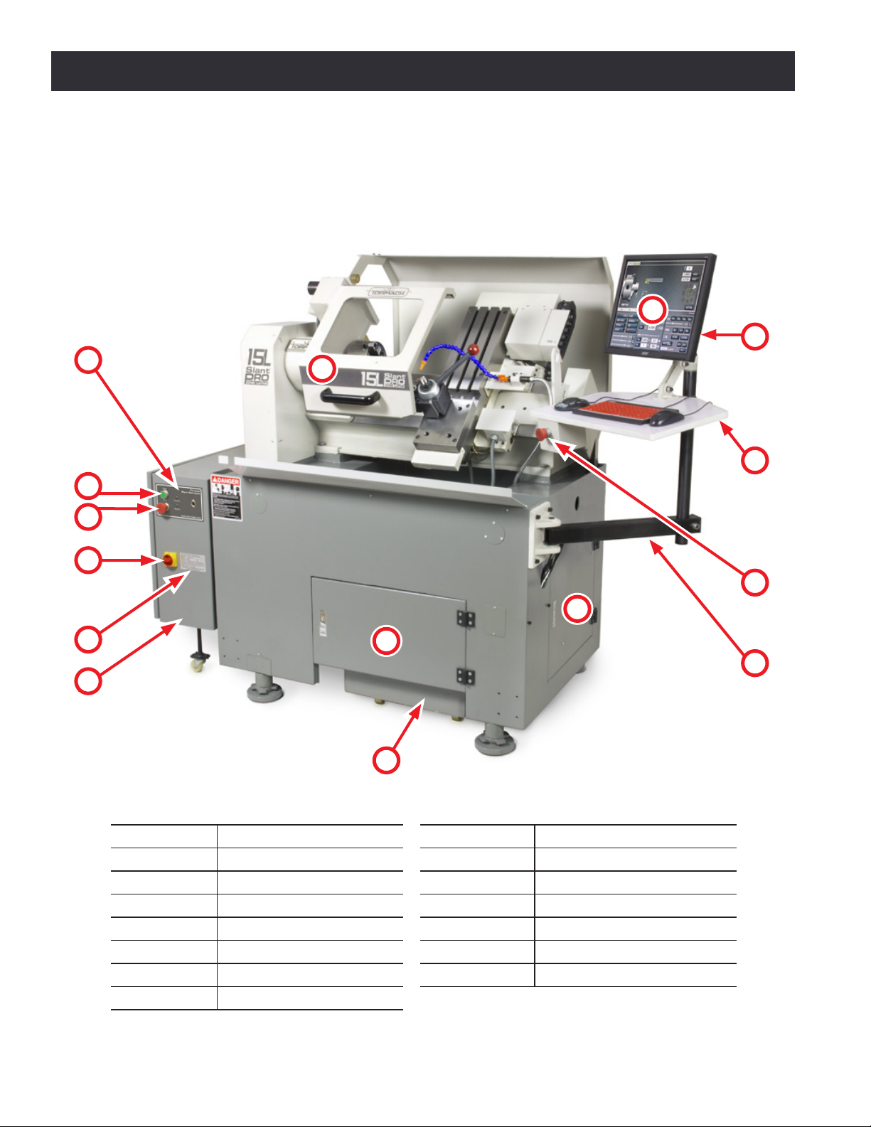
1. Overview
The 15L Slant-PRO lathe is a general purpose CNC lathe. Pictured below is a typical 15L Slant-PRO
lathe set up, including mulple opons.
Item # Component Name Item # Component Name
1Electrical Cabinet 9E-stop (remote)
2Serial Number Plate 10 Machine Arm
3 Main Disconnect 11 Controller Cabinet
4E-stop (panel) 12 Coolant Tank Door
5Start Buon 13 Coolant Tank
6 Operator Panel 14 PathPilot®Interface
7 LCD Monitor 15 Chuck Guard
8Keyboard Table
Figure 1.1
3
4
5
7
8
9
10
11
12
13
14
15
6
1
2

Chapter 1
19
UM10225_15L_Slant-PRO_Manual_0920A
Overview
1.1 Specifications
Mechanical
Travels
X-axis 10”
Z-axis 12”
Feed Rates Rapid Speeds 100 IPM
Key
Dimensions
Table Length 26”
Table Width 6”
Tool Holding
Gang tooling plate with three T-slots 0.625” (5/8”)
Center Slot: 0.00 + 0.004” – Outer Slots: 0.000 + 0.008”
Manual quick change tool post.
8-posion turret
Swing Over Bed 15”
Swing Over Carriage 6.2” (turret or manual tool post); 1.88” (gang plate)
Footprint 55” W x 66” H x 29” D
Spindle
Speed Range 300-3500 RPM (5C), 175-2500 RPM (6”chuck)
Horsepower 3 hp connuous
Drive System Cartridge style spindle with double V-belt transmission
Design D1-4 spindle w/ removable 5C taper insert
Temperature Operang Range 55°F-100°F (13°C-38°C)
Electrical
Power
Requirements
Primary (machine tool) 200 to 250 VAC1single phase
Secondary (control/coolant
systems) 115 VAC single phase
Recommended
Circuit Amperage2
Primary 20 AMP
Secondary 15 AMP (GFI protected)
1 230 VAC recommended; For voltages under 230 VAC, use of a Buck-Boost Transformer (PN 32554) is recommended.
2 Dedicated circuits recommended; do not use ground-fault interrupter (GFI) with primary circuit.

Chapter 2 20 UM10225_15L_Slant-PRO_Manual_0920A
Installation
2. Installation
2.1 Lathe Prep and Setup
2.1.1 Location
The area should be well lit, dry, have proper venlaon, provide for unobstructed machine moon
and operaon, and ensure unrestricted access to all lathe controls and the electrical cabinet.
2.1.2 Electrical Requirements
WARNING! Electrical Shock Hazard: Be sure to power o machine before making any electrical
modicaons. Failure to do so could result in serious injury or death.
• Primary: 200-250 VAC, 50/60 Hz at 20 Amps
NOTE: Connuous current is below 15 Amps, but requires a 20 Amp breaker or slow blow fuse
to prevent nuisance trips of the circuit breaker on spindle start.
Either use a NEMA L6-20 plug, or hard wire the machine. A cered electrician must make all
electrical connecons, and it’s your responsibility to verify that the electrical installaon of
the machine meets all local regulaons and electrical codes.
• Secondary: Separate wall outlet of 115 VAC, 50/60 Hz at 15 Amps
A separate wall outlet of 115 VAC at 15 Amps is required to act as power source for the
controller, monitor, and coolant pump. This connecon is made to the IEC power inlet at the
rear of the electrical cabinet.
For non-conforming sites:
1. Replace the stock coolant pump with a 230 VAC compable pump (Hi-Quality 1/8 HP
Coolant Pump Upgrade Kit, PN 33216), and change the Voltage Seng Switch on the
controller to 230 VAC (see Figure 2.8).
2. Use a step down transformer to convert 230 VAC to 110 VAC (Step-Up/Step-Down
Transformer, PN 32009).
2.1.2.1 Electrical Noise
Both primary and secondary power should be provided by dedicated circuits. At the minimum, circuits
should be isolated from electrically-noisy devices. In parcular, high-inducve loads from units like
vacuum cleaners or air compressors can be troublesome and/or cause controller malfuncon. For
non-conforming sites, refer to electrical requirement table earlier in this secon.
Other manuals for Slant-PRO 15L
1
Table of contents
Other Tormach Industrial Equipment manuals

Tormach
Tormach 37335 User manual

Tormach
Tormach PCNC 770 User manual

Tormach
Tormach 24R User manual

Tormach
Tormach MICROARC 4 User manual

Tormach
Tormach ATC User manual

Tormach
Tormach 1100MX User manual

Tormach
Tormach PCNC 1100 Deluxe Stand User manual

Tormach
Tormach CNC Scanner User manual

Tormach
Tormach PCNC 440 Technical manual

Tormach
Tormach Slant-PRO 15L User manual


