InstroTek Auto_SCB User manual
www.InstroTek.com
OPERATING MANUAL
innovators in instrumentation technology
Asphalt Load and Tension Testing
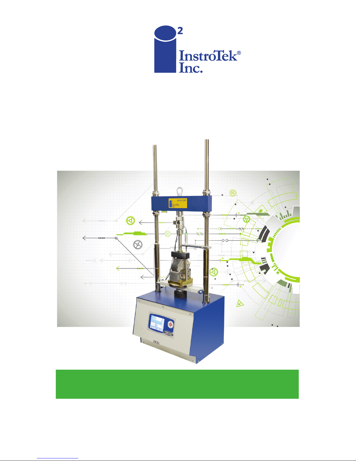
Auto_SCB
™

‘This page may be removed from the
manual to prevent the unauthorized
access to the restricted menu functions of
the InstroTek Auto_SCB.’
Restricted Menu Function Access
Codes:
System Configuration
Device Configuration (2222)
Channel Configuration (3333)
Profile Configuration (Golden Tags)
(1111)
Control Panel Software (5555)

This page may be removed from the
manual to prevent the unauthorized
access to the restricted menu functions of
the InstroTek Auto_SCB.

© 2018 InstroTek, Inc.
Auto_SCB Automated Load Frame for Measuring
Cracking in Asphalt Mixtures For
Illinois I-Fit (AASHTO TP124),
LSU Method (ASTM D8044),
And
IDEAL-CT (ASTM Draft)
Testing Protocols
Operation Manual Revision 6

IMPORTANT
WARNINGS WHEN USING THE
Auto_SCB™
DO NOT attempt any repairs while the unit is
powered on.
CAUTION DISCONNECT the unit from wall
power before attempting any repairs.
DO NOT operate this device without prior
training.
DANGER DO NOT insert any part of your body
between the ram and crosshead to prevent
crushing injuries.
Follow all your other related facility safety
instructions while operating this device.
Maintenance on this device must be done
by trained technicians.
Call InstroTek, Inc. (919-875-8371) if you have
any questions or before attempting any
repairs.
DO NOT USE the 10kN Load Cell for TSR testing. Please
contact InstroTek for information on different load cells and
accessories for the Auto_SCB.
IMPORTANT


InstroTek
1
1. Table of Contents
****************************************
1. INTRODUCTION 2
2. SYSTEM LOCATION 5
3. SYSTEM SPECIFICATIONS 5
4. SYSTEM SETUP 6
5. JIG SETUP 9
6. MAIN MENU 10
7. STATUS BAR & SYMBOLS 12
8. OPERATION 13
9. RUNNING THE TEST 16
10. RESULTS 21
11. DEVICE CONFIGURATION 22
12. CHANNEL ALLOCATION 24
13. DATA STORAGE & PRINTING 27
14. ALARMS 29
15. MANUALLY POSITIONING THE RAM 30
16. TEST ARCHIVE 31
17. SYSTEM CONFIGURATION & CALIBRATION 31
18. CHANNEL CONFIGURATION & CALIBRATION 34
19. CONTROL PANEL 37
20. MAINTENANCE 38
21. INDEX 39
22. WARRANTY 41

InstroTek
2
1. Introduction
InstroTek Auto_SCBTM is a load frame designed for conducting
semi-circular bend (SCB) tests described in AASHTO TP 124
(recommended by University of Illinois, I-Fit) and ASTM D8044
(recommended by Louisiana State University). Auto_SCBTM can
also perform a variety of mechanical property tests on asphalt
mixtures such as IDT strength, Marshall Stability, and IDEAL-CT.
The load and displacement parameters measured by the
Auto_SCBTM can be used to predict cracking performance of
asphalt mixtures. The Auto_SCBTM measures the load, the
specimen vertical displacement with a high accuracy linear
variable displacement transducer (LVDT) system, and an
encoder for the displacement of the ram of the load frame.
The loading sequence is fully automated with microprocessor
control of the loading ram such that the seating loads, rests,
unload rates, and loading rates are all performed consistently.
The load and displacement are measured with a built-in data
acquisition system. Also, an SCB jig has been developed to
improve repeatability of the test. All the functions of the
Auto_SCBTM system are automatically controlled and the results
are displayed on a touch screen.

InstroTek
3
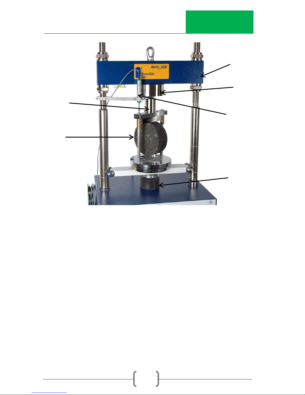
Machine Components
Loading Rod
SCB Jig
Reaction Bar
Reaction Bar
Load Cell
LVDT
Ram
Control Screen
(Touch Screen)
Fig 1. Auto_SCBTM Load Frame with SCB Jig
InstroTek
4
Loading Rod
Lottman
Breaking Jig
Reaction Bar
Load Cell
LVDT
Ram
Fig 2. Auto_SCBTM Load Frame with Lottman Breaking Jig

InstroTek
5
2. System Location
When setting up this unit, please select a location that can
meet the minimum requirements below.
1. The unit is designed to be a bench-top unit. Provide
adequate space for the user to utilize the control
screen and insert the SCB jig from the front of the load
frame.
2. Set the unit on a level and stable surface. It is
recommended that the unit be leveled before testing
using the attached feet.
3. System Specifications
Dimensions: 20” W x 18” L x 57” H
Weight: 300 lbs.
Displacement Speed: 0.01 –51 mm (0.0004 –2.0 inch)
per minute
Electrical Requirement: 120VAC, 150W, 1.5A
Maximum Ram Travel: 100 mm
LVDT Maximum Displacement: 25 mm
Load Capacity: 10 kN (2,200 lbs.) and optional 50 kN
(11,000 lbs.)

InstroTek
6
4. System Setup
The following steps will guide you through the required
connection for powering up the unit:
1. Plug the power cord in the appropriately rated outlet
(120VAC/15A).
2. Mount the load cell onto the threaded rod with the I-
bolt (as shown in Figure 1).
3. Attach the loading rod to the load cell.
4. Mount the LVDT holder onto one of the reaction frame
posts (as shown in Figure 1).
5. Plug either the 10 kN or (optional) 50 kN Load Cell into
Channel 1, LVDT into Channel 2.
6. Ensure that the nuts on either side of the reaction bar
are tightened by hand.
7. Power ON the Auto_SCBTM using the switch located on
the right side of the device next to the power cord.
8. The unit will perform a self-test and will show when
ready.
9. If an alarm ( ) is shown, please refer to the Alarms
section.

InstroTek
7
Reaction Bar and LVDT Height Adjustment
The following steps will guide you through positioning the
reaction bar and LVDT to work properly with the SCB or Lottman
Breaking jig:
1. Loosen the top bolts of the reaction bar to allow
the bar to move freely upward.
2. Enter the test menu .
3. Place the test jig on the ram by aligning the
centering pin in the ram and the slot in the jig.
NOTE: The centering pin can be removed if the jig does
not have a slot.
4. Place an asphalt specimen in the test jig (see
Figure 3).
5. Press the TEST Position button.
6. Raise or lower the reaction bar so that the
loading rod is within 2 mm (thickness of a penny)
but not touching the loading bar on the test jig
and centered over the jig loading bar.
7. Tighten the top bolts of the reaction bar by
hand.
8. Clamp the LVDT in the LVDT holder. Adjust the
LVDT until it reads 2-5 mm while in the TEST
position. This will allow sufficient clearance for

InstroTek
8
the jig to slide in and out when in the HOME
position with the LVDT in place.
NOTE: Tighten the LVDT holder thumb screws finger tight
to prevent damaging the LVDT.
InstroTek
9
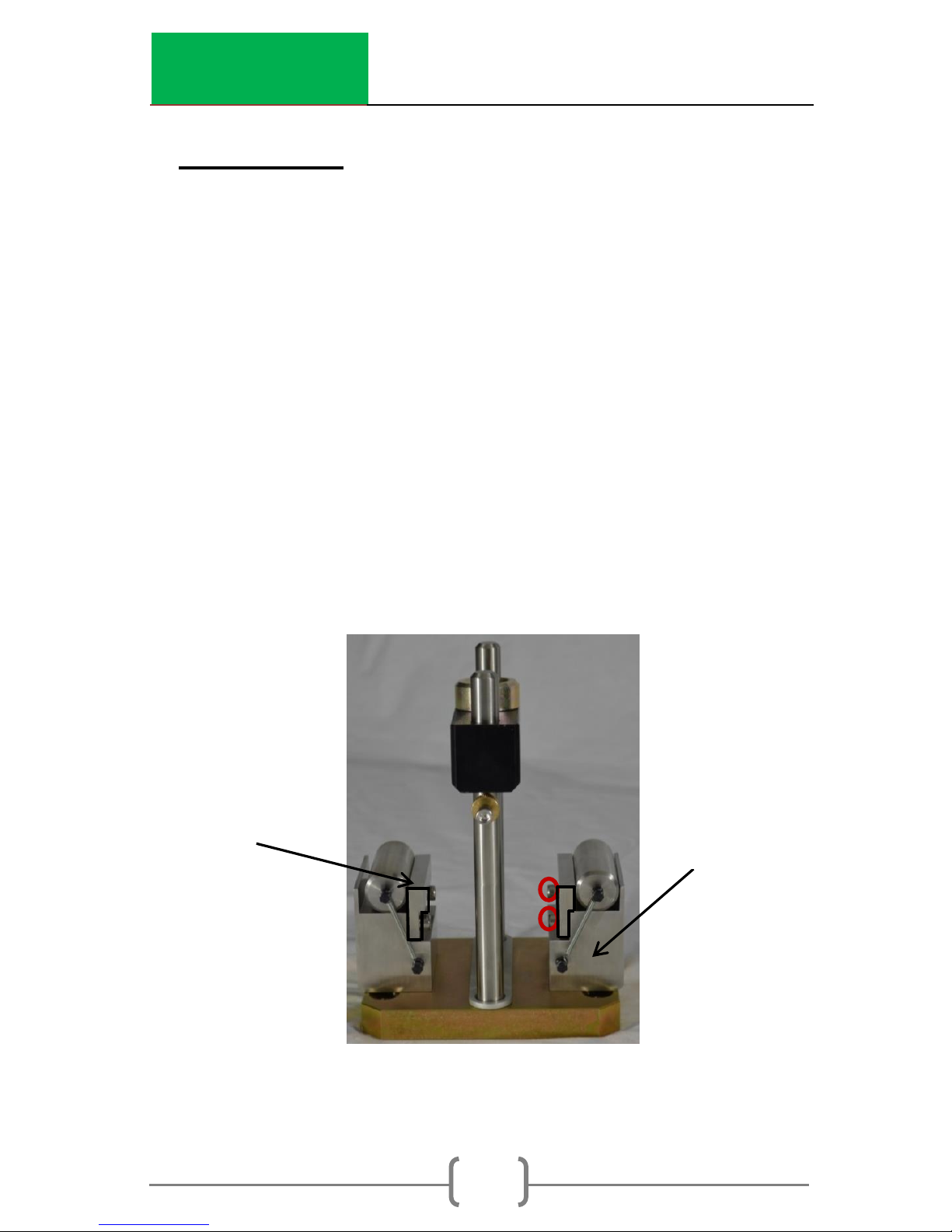
5. Jig Setup
The SCB jig is designed to comply with the requirements of both
the I-FIT and LSU SCB standards. The difference in the jig for the
standards is the spacing between the rollers. The I-FIT (AASHTO
TP 124) test requires an 120 mm spacing while the LSU (ASTM
D8044) test requires an 127 mm spacing.
1. Remove the two screws (5/32” Allen wrench) from the
roller support, as shown in the circles in Figure 3.
2. Flip the mounting block around until it is oriented like
the appropriate method.
a. I-FIT –the mounting block is flush to the roller
support.
b. LSU –the mounting block overhangs the roller
support.
Fig 3. SCB Jig Setup
NOTE: SCB Jig may look different but still functions the same.
I-FIT
Mounting
Block
Roller Support
Roller
Support
LSU
InstroTek
10
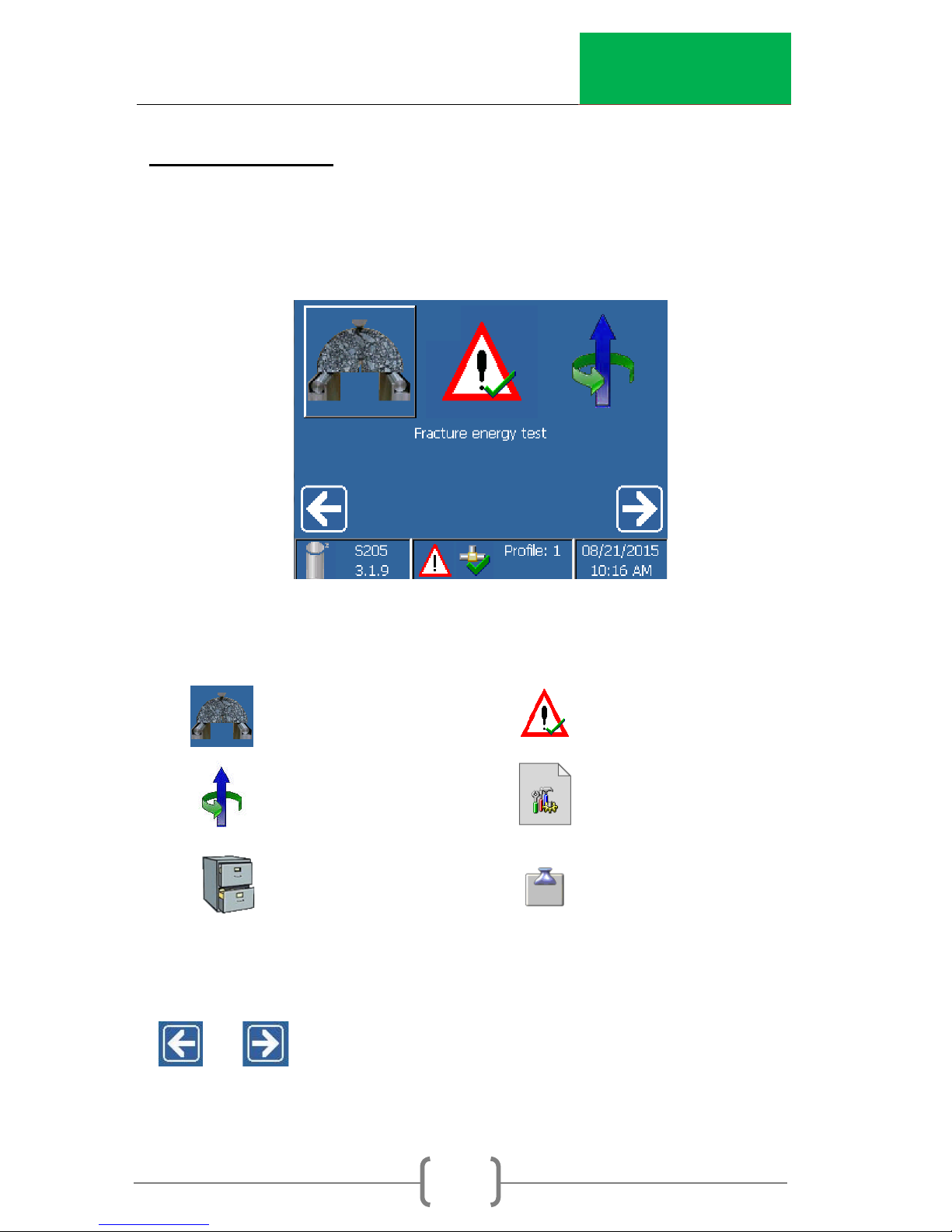
6. Main Menu
The Main Menu allows the user to select the main functions of
the machine.
The main functions are:
Cracking Test Active alarms
Ram Position
Test archive Control panel
Select an item with the touch-screen: Scroll through the menu
or until the desired menu item is highlighted and
select the item by touching the screen.
System config.
Cracking Test
Position

InstroTek
11
Select an item with the keypad: Scroll through the menu using
the arrow keys or until the desired menu is
highlighted. Push the Enter key to select an item.
InstroTek
12
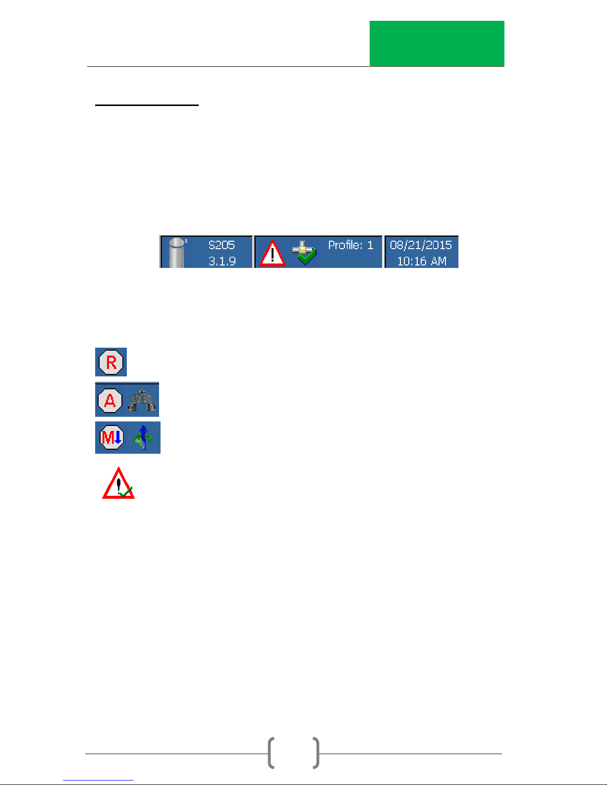
7. Status Bar
The bottom of the main screen contains the status bar. The left
side of the status bar provides the current software version
installed on the machine. The center of the bar provides the
current status of the machine. The right side provides the
current date and time.
Status Symbols
Machine is ready to test
Running the test (automatic)
Moving the ram (manually)
Warning

InstroTek
13
8. Operation
This section will provide a general guide to set up, run, and
record the data for a test in the Auto_SCBTM.
Sample Preparation for SCB
1. Prepare specimens according to the instructions in the
relevant standard.
a) I-FIT –AASHTO TP 124
b) LSU –ASTM D8044
NOTE: Specimens may be prepared using the gyratory
compactor, kneading compactor, cores cut from the field, or
slabs from a laboratory compactor. Consistent air voids are
necessary for consistent results.
2. Saw cut the specimens to the desired thickness. Measure the
air voids of the circular disks.
a) I-FIT –Gyratory-prepared specimen thickness shall
be 50 ± 1 mm.
b) LSU –Gyratory-prepared specimen thickness shall be
57 ± 1 mm.
3. Cut the specimens in half. Then, create a notch in the
sample to the depth(s) specified in the standard.
a) I-FIT –Notch width shall be 1.5 ± 0.1 mm and the
depth shall be 15 ± 1 mm for all samples.
b) LSU –Notch width shall be < 3.5 mm and the notch
depth shall be 25, 32, or 38 mm ± 1 mm.

InstroTek
14
NOTE: A wet saw, tile saw, or table saw with a
masonry bit may be used to consistently cut the
notch.
4. Insert a specimen into the SCB Jig (Figure 4). Adjust the
horizontal alignment bolt such that the specimen is
centered on the roller supports. Raise the perpendicular
alignment bar into the notch cut into the specimen to align
it perpendicularly to the horizontal alignment bolt.
Table of contents
Other InstroTek Test Equipment manuals


