7 8
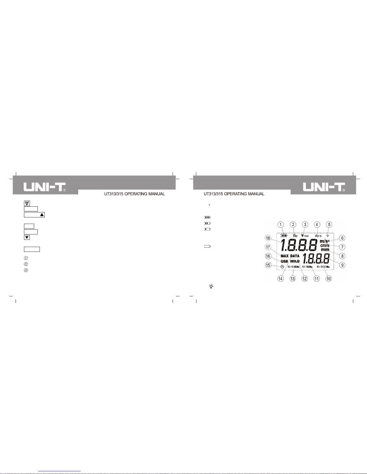
6. M/s2: acceleration unit indicator
In velocity measurement, LCD display the velocity unit m/s
7. cm/s: velocity unit indicator
8. mm: displacement unit indicator
9. Data record number display area
10. 10-500Hz: 10Hz-500Hz indicator
11. 10-1kHz:10Hz-1kHz indicator.
12. HOLD: reading hold measurement
13. 10-10kHz: 10Hz-10kHz indicator
14. DATA: data storage indicator
16. USB: USB indicator
17. MAX: maximum value measurement indicator
18. Measurement data value display area
15. : Automatic power-off function indicator
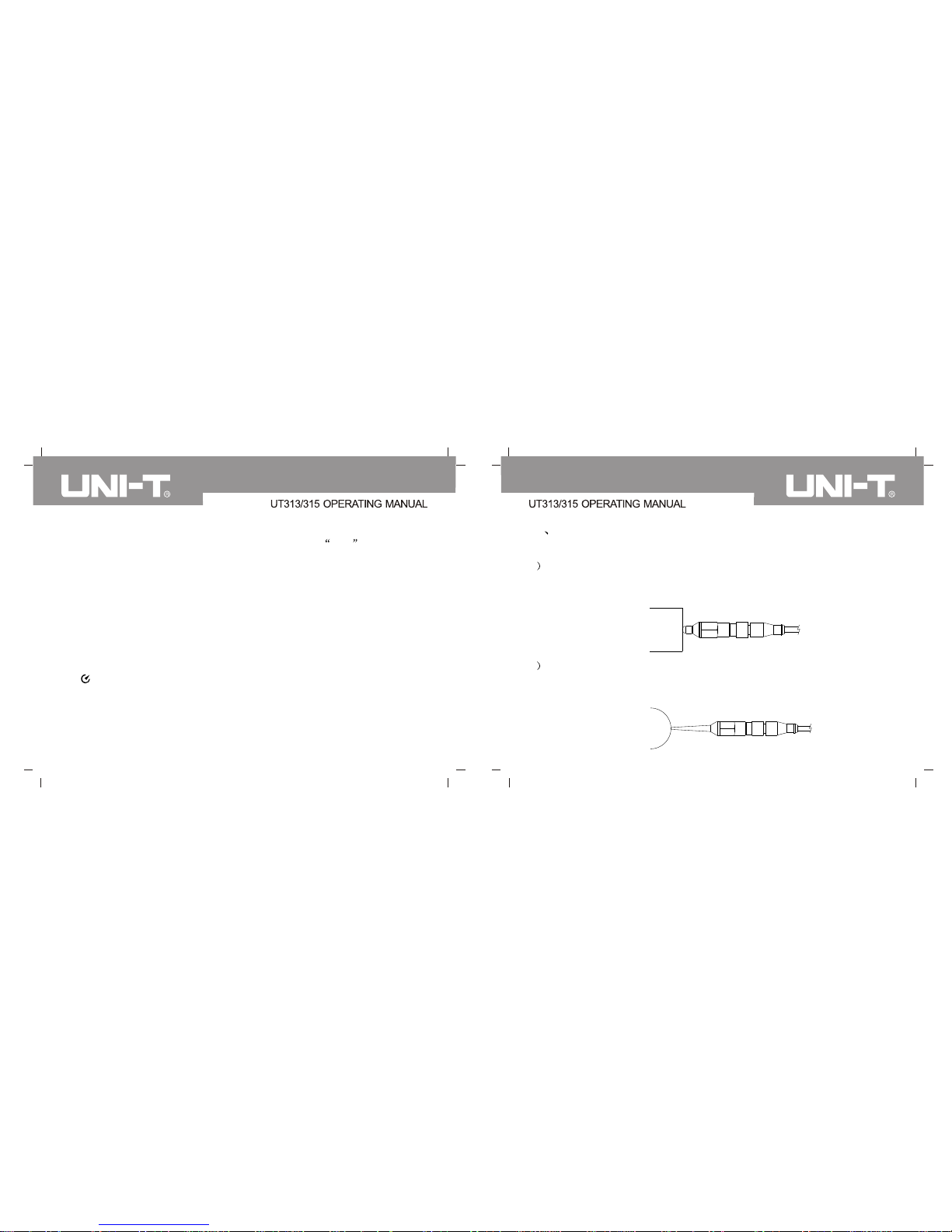
VI Select test method
Please select test method based on real status, four statuses:
1 Use short(s) probe to measure: it is installed with the machine and
applicable to wide scope vibration measurement; it can acquire effective
response numerical value, as shown in the following illustration
2 Use long (L) probe to measurement: it is an accessory in a package,
mainly used in rather narrow or special object area, with quick response,
as shown in the following illustration