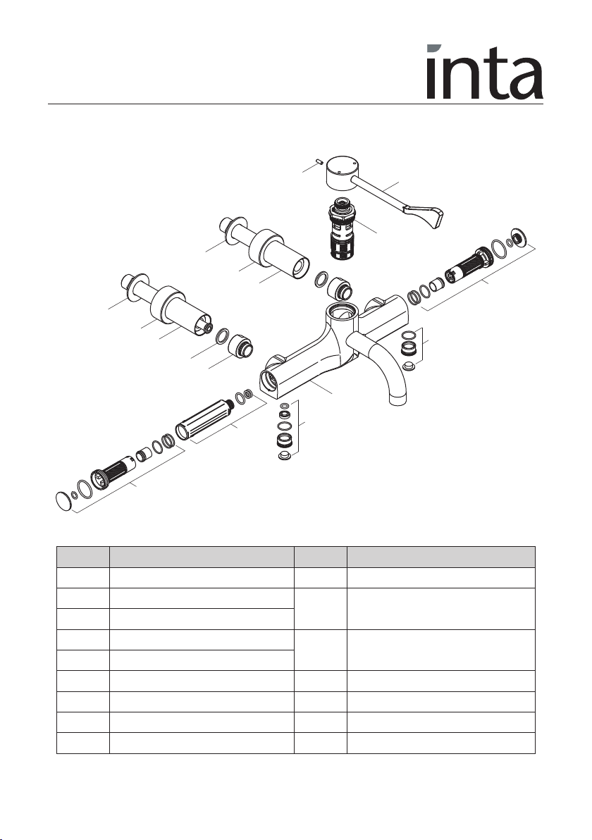
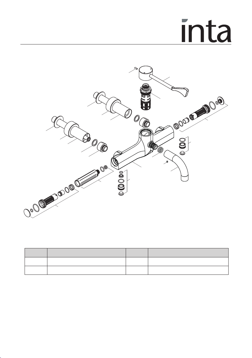
Inta HTMWMCP User manual

Wall & Deck Mounte
Sequential Control
Thermostatic Mixer
HTMWMCP, HTMDMCP
HTMWMRS & HTMDMRS
Installation an Maintenance Instructions
In this procedure document we have endeavoured to make the
information as accurate as possible.
We cannot accept any responsibility should it be found that in
any respect the information is inaccurate or incomplete or
becomes so as a result of further developments or otherwise.
Intatec Ltd
Airfield Industrial Estate
Hixon
Staffordshire
ST18 0PF
Tel: 01889 272 180
Fax: 01889 272 181
email: [email protected]
web: www.intatec.co.uk
© Intatec td. 2016

© Intatec Ltd 2016 1
Contents
Thank you for choosing the Inta lever operated thermostatic wall mixer.
Subject Page
Introduction 2
Technical Data 2
Components - Wall Mounted 3
Components - Wall Mounted with Removable Spout 4
Components - Deck Mounted 5
Components - Deck Mounted with Removable Spout 6
Dimensions 7
Installation 8
Operation 9
Trouble Shooting 9
Re-calibration 10
Cartridge Removal 10
Aftercare 11
Removing Spout and Disinfection 12
System Flushing Procedure 13
Sterilization Process 14
TMV3 Installation Instructions 16
Guarantee 21

© Intatec Ltd 2016 2
Introduction
This installation guide has been produced for the wall and deck mounted sequential control
mixer. These instructions cover the installation, operation and maintenance. Please read the
enclosed instructions before commencing the installation of this product, please note;
We recommend that the installation is carried out by an approved
installer.
The installation must be carried out strictly in accordance with the Water Supply (Water Fitting)
Regulations 1999 and any local authority regulations.
If in doubt we recommend that you contact WRAS - Water Regulations Advisory Scheme on
Tel: 0333 207 9030, your local water authority - details available on the WRAS website or the
Chartered Institute of Plumbing and Heating Engineers on Tel: 01708 472 791.
All products MUST be re-commissioned to suit site conditions to ensure optimum performance
levels of the product are obtained.
Check Content
Before commencing remove all components from packaging and check each component with
the contents list.
Ensure all parts are present, before discarding any packaging. If any parts are missing, do not
attempt to install your control mixer until the missing parts have been obtained.
Product Range
HTMWMCP - HTM safe touch thermostatic sequential wall mounted tap.
HTMDMCP - HTM safe touch thermostatic sequential deck mounted tap.
HTMWMRS - HTM safe touch thermostatic sequential wall mounted tap with removable spout.
HTMDMRS - HTM safe touch thermostatic sequential deck mounted tap with removable spout.
Technical Data
This Inta thermostatic mixer is suitable for installations on all types of plumbing systems, including
gravity supplies, fully pumped, modulating combination boiler, unvented water heater and
unbalanced supplies i.e. Cold Mains & Tank Fed Hot.
Max Dynamic Pressure 5 bar Min Operating Pressure 1.0 bar
Max Static Pressure 12 bar Min Inlet Temperature 10˚C
Max Inlet Temperature 85˚C Temperature Stability ±2˚C
Pre Set Factory Temp Setting 41˚C Min Temp Differential to
Max Unbalanced Pressure Ratio ensure fail-safe between hot
Without Flow Regulator 5:1 and cold supplies 10˚C
Preparation or Installation
Before starting the installation, ensure that the site conditions are suitable - see Technical Data.
The tap is supplied for wall or deck mounting as shown.
Flush the water supply pipes thoroughly prior to installation - see page 13. Do not allow debris,
PTFE tape or any metal particles to enter the mixer.

© Intatec Ltd 2016 3
Item Description Item Description
1 Body inc. Outlet Diffuser 10 Hot Water Insulator
2 Thermostatic Cartridge 11 Cold Water Inlet Assembly
including 5 l/m flow regulator
3 ever
4 ever Retaining Screw 12 Hot Water Inlet Assembly
including 5 l/m flow regulator
5 Concealing Plate
6 Cold Water Inlet Tail Assembly 13 Hot Water Port Blanking Assembly
7 Hot Water Inlet Tail Assembly 14 Cold Water Port Blanking Assembly
8 Sealing Washer 15 Backnut
9 Swivel Nut
Components - Wall Mounted with Fixed Spout
1
2
3
4
5
6
5
7
8
9
11
13
14
15
15
10
12

© Intatec Ltd 2016 4
Item Description Item Description
1 Body 18 Spout Retaining Screw
17 Spout 19 ‘O’ Ring
Components - Wall Mounted with Removable Spout
Additional Components - Removable Spout
1
2
3
4
5
6
5
7
8
9
11
13
14
15
15
10
12
17
18
19

© Intatec Ltd 2016 5
Item Description Item Description
1 Body inc. Outlet Diffuser 10 Hot Water Insulator
2 Thermostatic Cartridge 11 Cold Water Inlet Assembly
including 5 l/m flow regulator
3 ever
4 ever Retaining Screw 12 Hot Water Inlet Assembly
including 5 l/m flow regulator
5 Concealing Plate
6 Cold Water Inlet Tail Assembly 13 Hot Water Port Blanking Assembly
7 Hot Water Inlet Tail Assembly 14 Cold Water Port Blanking Assembly
8 Sealing Washer 15 Backnut
9 Swivel Nut 16 Washer - Chrome
Components - Deck Mounted with Fixed Spout
1
2
3
4
11
6
5
8
9
7
5
13
14
16
15
10
12

© Intatec Ltd 2016 6
Item Description Item Description
1 Body 18 Spout Retaining Screw
17 Spout 19 ‘O’ Ring
Components - Deck Mounted with Removable Spout
1
2
3
4
11
6
5
8
9
7
5
13
14
16
15
10
12
17
18
19
Additional Components - Removable Spout

© Intatec Ltd 2016 7
Dimensions - Wall Mounted
Dimensions - Deck Mounted
37
G½B
12875 105
186.5
Ø45
266
116.5
Ø50 Ø33
75 187.5
200
G B
Ø50
Ø33
100

© Intatec Ltd 2016 8
Installation
Wall Mounting
• The tap is supplied as shown in the Components section except that the thermostatic cartridge
(2) and swivel nut connectors (9) are fitted into the body.
• Fit the concealing plates (5) onto the tailpieces (6) & (7).
• Screw the tailpiece (6) into the cold water inlet of
the tap, right hand side when facing the tap.
ATTENTION: The hot water inlet connection tail
can be i entifie by the brass insulator pipe that
protru es past the connecting threa .
Care must be taken to ensure the Hot Water Inlet
Tail Assembly is connecte securely into the hot
water inlet of the tap bo y.
• Screw the tailpiece (7) into the hot water inlet of
the tap, left hand side when facing the tap.
• For wall mounting fit the tap assembly to the
mounting panel, using the back nuts (15) and slide
the concealing plates to the panel.
• Care should be taken that the maximum panel thickness does not exceed 33mm..
• Connect the supply pipes to the tap, cold on the right, hot on the left.
• Fit the lever (3) to the tap using the grub screw (4) provided.
• Please ensure that the hydraulic installation is completed and that all check valves are open.
Deck Mounting
• Screw the tailpiece (6) into the cold water inlet of the tap, right hand side when facing the
tap.
ATTENTION: The hot water inlet connection tail can be i entifie by the brass
insulator pipe that protru es past the connecting threa . Care must be taken to ensure the
Hot Water Inlet Tail Assembly is connecte securely into the hot water inlet of the tap
bo y.
• Screw the tailpiece (7) into the hot water inlet of the tap, left hand side when facing the tap.
• For deck mounting fit the tap assembly to the basin, using the washers (16) and back nuts
(15) (supplied) and slide the concealing plates to the basin.
• Connect the supply pipes to the tap, cold on the right, hot on the left.
• Fit the lever (3) to the tap using the grub screw (4) provided.
• Please ensure that the hydraulic installation is completed and that all isolation valves are in
the open position.
Cold water
inlet tail
Sealing
washer
6
Hot water
inlet tail
7

© Intatec Ltd 2016 9
As the handle is rotated anti-clockwise from the off position the delivered water progresses from
cold, through warm to the pre-set maximum temperature of approximately 43˚C.
Operation
Trouble Shooting
Fault Diagnosis
Mixed water temperature is not hot enough. Ensure the hot water supply is at a constant
temperature above 60˚C.
Re-calibrate as per page 10.
Check for airlocks in the pipework.
The water goes cold during operation. Insufficient stored hot water supply.
Ensure that the boiler is still firing for combi
boilers.
Adjust the boiler control to a minimum setting
of 65˚C not necessarily the best flow rate.
Temperature is too hot or when set to Check the commissioned maximum
hot water runs cold. temperature of the valve. Check connections
to the mixer are not reversed.
Flow of water through the valve is low. Check the filters are clean and supply
pressure is above 1 bar.
No flow of water. Ensure the mixer has not fail-safed,
and check that there is water flow to the mixer
and the service valves are not closed - see
exploded drawing.
Off
Warm
Cold
Max. blend
temperature
(preset)
Hot Supply Cold Supply

© Intatec Ltd 2016 10
Re-Calibration
The factory setting at 41˚C can be altered to suit site conditions.
Warning: Care must be taken when altering the setting as incorrect calibration can cause injury.
• Remove the grub screw.
• ift the handle cover off.
• Re-calibrate by removing the temperature stop rings from the cartridge and set the mixed water
to the required temperature by temporarily re-fitting the control lever.
• Once the required temperature is achieved replace the two temperature stop rings on the
splined spindle of the cartridge as shown. These two rings are used to prevent the temperature
of the cartridge from being altered whilst in use. The stop rings should be locked at either end
of the operating cycle and will form a physical stop to prevent the cartridge turning (see
below)
• Refit the lever assembly and grub screw.
• Recheck the calibrated temperature
A
B
A
A
BB
Remove rings and
set water temperature
Replace rings
as shown
Rings act
as stops
Cartridge removal
1 Unscrew the retaining screw and remove the lever.
2 The thermostatic cartridge is a single piece construction and should be unscrewed
anti-clockwise from the mixer body using a suitably sized spanner.
3 When re-installing the cartridge into the mixer body, it should be tightened to a maximum
torque of 15 Nm

© Intatec Ltd 2016 11
A tercare
• With all highly polished items, care should be taken not to damage any of the external
surfaces.
• We recommend that to ensure the physical appearance of the product and component parts
that it is periodically cleaned with a soft damp cloth and a mild detergent. The use of abrasive
or solvent cleaners will damage the finish of the product.
• We recommend periodically that the flow straightener is cleaned using a suitable scaling
solvent. Check first it does not affect the plated surface.
• The internal bore of the flow straightener must be periodically wiped using a damp cloth.
• We recommend that this fitting is serviced at least once a year.
• Only use genuine spare parts, the full list is available on request by ringing the Technical
Helpline number on the back page.
Removing Spout
The HTMWMRS wall mounted and HTMDMRS deck mounted taps have a removable spout to
assist with cleaning, disinfection by immersion or sterilisation in an autoclave.
Inta recommend that a replacement spout is available as the tap should not be left without
a spout (HTMSP16XX).
Cleaning, disinfection and sterilisation is only necessary if there is evidence of solid deposits
around the outlet from the tap or a minimum of once per year.
• Ensure the isolation valve in both supplies to the tap are in the closed position and the lever is
also in the closed position to prevent water flow and potential flooding.
Internal bore
in flow
straightener

© Intatec Ltd 2016 12
• Using a suitably sized Allen key unscrew the grub screw (18) located beneath the spout.
The grub screw must be removed completely to ensure the ‘O’ rings are not damaged when
the spout is pulled away.
• Pull the spout (17) away for the body of the tap, care should be taken to prevent damage to
the chrome finish of the spout.
• Check the condition of the two ‘O’ rings (19) on the spigot of the tap body, if damaged they
must be replaced.
Once the spout has been removed disinfection or sterilisation can commence.
• The spout can be sterilised in an Autoclave following standard sterilisation procedures.
• The spout after disinfection and sterilisation should be stored in such a manner that they will not
become infected or dirty before refitting.
Re itting Spout
• When refitting the spout lubricate the two ‘O’ rings with a suitable lubricant to ease
re-assembly.
• Fit and re-tighten the grub screw (18).
• Open the isolation valve in both supplies to the tap.
• Only use genuine spare parts, the full list is available on request by ringing the Technical
Helpline number on the back page.
Removing Spout
17
18
Lever in closed
position
19

© Intatec Ltd 2016 13
System Flushing Procedure
The water system must be thoroughly flushed before attempting to commission or operate this tap to
ensure all pipework is clean and free from any debris. This system flushing procedure allows the
process to be efficiently conducted with the tap installed. Failure to carry out effective system flushing
before commissioning or operating this product could damage or limit the performance of the
product and invalidate the product guarantee.
A
Waste water flushed
through outlet with
hose connected
7 - Flushing
(hose not supplied)
90° OPEN
CLOSE
1 - Move handle to closed position
Water must not pass through
the tap before completing
system flushing
2 - Ensure both isolation valves
are in the closed position
2A - Turn to closed
position
3 - Remove end cover from
the hot supply end of
the tap
1
2
4 - Carefully remove check valve
housing using the extraction
tool (HTMSP20XX) and rotating
anti-clockwise
5 - Screw in connector plug using
suitably sized spanner
6 - Attach hose connector
(HTMFLUSH)
90° OPEN
CLOSE
6A - Turn to open
position
Hot
supply
pipework
flushed

© Intatec Ltd 2016 14
System Flushing Procedure
Sterilization Process
NOTE: Not a replacement or chlorination
90° OPEN
CLOSE
8 - Ensure the isolation valve
on the hot supply is
closed before
9 - Unscrew the connector plug using
suitably sized spanner and refit
the check valve and end cover
10 - Repeat the procedure for the
cold inlet side before opening
both isolation valves
REMOVE
1 - Move handle to open position 2 - Isolate both inlet tails
2A - Turn to the
closed position
90° OPEN
CLOSE
3 - Remove the cover from each
inlet
4 - Remove hot and cold inlet plugs
using a 10mm Allen key
4A

© Intatec Ltd 2016 15
Sterilization Process
5 - Fit the cold inlet plug into the hot
position and the hot into the
cold position
By carrying out the above procedure you are sterilizing the complete tap with hot water
6 - Open the ball valve on the hot
supply to start sterilization
procedure
90° OPEN
CLOSE
6A - Turn to open
position
7 - Close the isolation
valve
90° OPEN
CLOSE
8 - Refit the hot inlet plug into the hot position
and the cold into the cold position and refit
the covers
90° OPEN
CLOSE
9 - Open the isolation valve
and move the handle
to the closed position
Temperature Disinfection time
60˚C
65˚C
70˚C
20 minutes
10 minutes
5 minutes
10 - Disinfection times based
on water temperature

© Intatec Ltd 2016 16
Code Application Range
HP-W Basin High Pressure
Operating Pressure Range High Pressure ow Pressure
Maximum Static Pressure 10 bar 10 bar
Flow Pressure, Hot and Cold 1 to 5 bar 0.2 to 1 bar
Hot Supply Temperature 55˚C to 65˚C 55˚C to 65˚C
Cold Supply Temperature 5˚C to 20˚C 5˚C to 20˚C
When this Mixer is used in a DO8 Application the ollowing Instructions apply:
Introduction
This Inta Thermostatic Mixer has been specifically esigne an manufacture to meet the
requirements of BS 7942: 2000 an NHS D08. The pro uct has been in epen ently teste
an approve as a TYPE 3 valve un er the TMV3 scheme.
Technical Speci ication
Application
This thermostatic mixer has been independently tested by WRc and certified as meeting the
requirements of the NHS D08 specification under the TMV3 Scheme as being suitable for use
on the following;
Outlet Temperature Adjustment Range 30˚C to 50˚C
Temperature Stability ±2˚C
Maximum Hot Inlet Temperature 85˚C
Inlet Temperature Range 55˚C to 65˚C : Hot Supply
5˚C to 20˚C : Cold Supply
DO8 Working Pressure Range 0.2 to 1.0 bar : ow Pressure
1.0 to 5.0 bar : High Pressure
Min Temp Differential (Mix to Hot) for Fail-Safe 10˚C
Max. Pressure Inlet Differential 5 : 1
Max. Flow Rate @ 1 bar Differential Ø15mm 1500 l/h (25 l/m)
Ø22mm 1700 l/h (28.3 l/m)

© Intatec Ltd 2016 17
Installation
IMPORTANT – The following instructions must be read prior to the installation of any Inta
thermostatic mixing valve.
The installer should also be aware of his responsibility and duty of care to ensure that all aspects
of the installation comply with all current regulations and legislations.
It has been brought to our attention that flushing water systems using certain chemicals may affect
the workings of the valve, which may adversely affect its performance.
We recommend that following system flushing with chemicals, mixers are checked for correct
operation.
1. It is essential that, before installing a thermostatic mixing valve, the supply conditions of the
system to which the valve is intended to be fitted are checked to confirm compliance with the
parameters as quoted within the Technical Specification above and conditions on which the
approval is granted i.e. verify supply temperatures, supply pressures, risk assessments etc
2. Consideration must be made for the possibility of multiple/ simultaneous demands being made
on the supply system whilst the thermostatic mixing valve is in use, all practical pre-cautions
must be made to ensure that the valve is not affected. Failure to make provision within the pipe
sizing etc will affect the performance of the valve.
3. The supply system to which the Thermostatic Mixing Valve is to be installed into must be
thoroughly flushed and cleaned to remove any debris (see page 13), which may be
accumulated during the installation. Failure to remove any debris will affect the performance
and the manufacturer’s warranty on the product.
4. Independent filters/check valves and isolation valves must be fitted in conjunction with the
valve. In areas that are subject to hard water, provision must be made to treat the supplies
prior the supplies entering any product.
5. The maximum flow rate of the valve will only be achieved when the supply conditions are
achieved as quoted, with a flow condition under 1 bar differential pressure.
6. This Inta thermostatic mixer has been designed to be wall mounted. It is essential that access to
the valve is not obstructed for future maintenance, that may be required to the valve or
associated fittings.
7. The connection of the hot and cold supplies must be in accordance with the instructions shown
on page 8 i.e. hot water connected to the left hand side of the valve when the nozzle is facing
you.
8. In a situation where one or both of the water supplies are excessive, it is recommended to fit a
Pressure Reducing Valve, WRAS approved product, to reduce the pressure(s) to within those
stated in the Technical Specification previously stated or a suitable flow regulator.
9. We recommend that Y pattern strainers and full bore isolation valves are installed in
conjunction with this product as close as practically possible to the location valve.

© Intatec Ltd 2016 18
Application Recommended Set Hot Water Temperature
Wash Hand Basin 41˚C
Installation
10. It is essential that this product should not be installed in situations where there is a possibility of
the valve being deprived of water or where demands for water are greater than the actual
stored supplies.
11. To ensure that the performance levels of this Thermostatic Mixing Valve are maintained (in the
event of cold water failure) the temperature of the hot water supply at the point of entry to the
valve must be a minimum of 10°C above the commissioned mixed water discharge
temperature.
12. This Thermostatic Mixing Valve must not be subject to any extreme temperature variations
either during the installation or under normal operating condition
Commissioning
IMPORTANT – The following instructions must be read and understood prior to the commissioning
of a Thermostatic Mixer. If under any circumstances there are aspects to the installation/system which
do not comply with the specification laid down, the valve MUST NOT is put into operation until the
system/installation complies with our specification.
1. Ensure that the system is thoroughly cleaned and free from any debris prior to the
commissioning of the valve. (See page 10)
2. The commissioning of the temperature must be carried out using a suitably calibrated
thermometer – preferably a digital thermometer. (See page 8)
3. In the absence of other temperatures being specified we recommend that the outlet
temperatures quoted in table 1 are used, extracted from the “National Health Service –
Health Guidance Note – Safe Hot Water and Surface Temperatures”.
Table 1
4. Each valve must be commissioned taking into consideration any fluctuations, which may
occur within the system due to simultaneous demands. It is advisable that any outlets which
are connected to the same supply as the mixing valve are opened during setting of the
mixed water temperature. It is advisable to ensure that the water temperatures are
established before any attempt to commission.
5. Once the supply temperatures are stable and the normal operating conditions are
established, the valve can be commissioned. We suggest that the following sequence is
followed when commissioning the valve:
5.1 Using the lever turn to the maximum hot setting of the tap, the mixed water temperature
should be preset (see page 8).
5.2 Measure and record the temperature of the hot and cold water supplies at the
connections to the valve.

© Intatec Ltd 2016 19
Application Maximum Hot Water Temperature
Wash Hand Basin 43˚C
Table 2
Commissioning
5.3 Measure and record the temperature of the water discharging from the valve for the
largest and smallest draw off point.
5.4 Isolate the cold water supply to the valve and monitor the mixed water temperature.
5.5 Measure and record the maximum mixed water temperature and the final temperature.
The final temperature found during the test should not exceed the values quoted in
table 2.
5.6 Record all the equipment used during the commissioning.
6. Ensure that the application, to which the valve will be used, is appropriate for the approved
designation.
7. The above information must be recorded and updated on every occasion when any work is
carried out on the valve.
In Service Testing
To ensure that the Thermostatic Mixer maintains a high level of protection, we advise the following in
service testing is followed (the same equipment used to commission the valve initially must be used in
the following tasks).
1. After a period of between 6 and 8 weeks after commissioning carry out the following.
a) Record the temperature of the hot and cold water supplies.
b) Record the temperature of the mixed water at the largest draw off flow rate.
c) Record the temperature of the mixed water at the smallest draw off flow rate.
2. If the mixed water temperature has changed significantly from the previous test results
(e.g. > 1 k), record the change and before re-setting the mixed water temperature check that:
a) All the strainers are clean
b) All the check valves are in good working order
c) The isolation valves are fully open.
This manual suits for next models
3
Table of contents
Other Inta Plumbing Product manuals
Popular Plumbing Product manuals by other brands

Signature Hardware
Signature Hardware CLARISSA installation instructions

Elkay
Elkay Hi-Arc LKD2448BH Specifications

American Standard
American Standard WILLIAMSBURG 2900.222.002 Specifications

VIGO
VIGO LINUS VG03013 manual

Bradley
Bradley Express EXD Series installation instructions

Hans Grohe
Hans Grohe Croma E 280 Instructions for use

Hans Grohe
Hans Grohe ShowerSelect 15744 1 Series Installation and user instructions

Axor
Axor 51307 Series Assembly instructions

Elkay
Elkay LKEC2031AS Installation & owner's manual

Kinedo
Kinedo H2O Solo PA720CTNE installation instructions

Sanela
Sanela SLP 19RZ Instructions for use

Gessi
Gessi OVALE 23099 manual