Intec Controls PolyGard MGC2-04 User manual

12700 Stowe Drive, Suite 100, Poway, CA 92064 | Ph: (858) 578.7887 & (888) GO.INTEC | relevantsolutions.com/inteccontrols
August 11, 2016 – Revision
PolyGard®is a registered trademark of MSR-Electronic GmbH
BUILDING SOLUTIONS
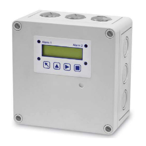
Analog Gas Controller
PolyGard®MGC2 - 04, 08, 12, 16, 20, 24
User Manual
June 2012

12700 Stowe Drive, Suite 100, Poway, CA 92064 | Ph: (858) 578.7887 & (888) GO.INTEC | relevantsolutions.com/inteccontrols
Specifications subject to change without notice. | USA 160811 | Page 2of 34
MGC2 – UserManual
PolyGard®is a registered trademark of MSR-Electronic GmbH
1 Application .......................................................................................................................................................4
2 Description .......................................................................................................................................................4
2.1 Normal Mode...............................................................................................................................................4
2.2 Alarm Mode .................................................................................................................................................4
2.3 Fault Mode .................................................................................................................................................. 4
3 Operating Instruction ...................................................................................................................................... 5
3.1 Description Keypad User Interface..............................................................................................................5
3.2 Setting / Change Parameters or Setpoints..................................................................................................5
3.3 Code Levels ................................................................................................................................................ 6
4 Menu Overview.................................................................................................................................................7
4.1 Fault Management ...................................................................................................................................... 8
4.1.1 Acknowledge a Fault.............................................................................................................................8
4.1.2 Error Memory........................................................................................................................................8
4.1.3 System Errors ....................................................................................................................................... 9
4.2 Status Alarm.............................................................................................................................................. 10
4.3 Status Relay.............................................................................................................................................. 10
4.3.1 Manual Operation of the Relays ......................................................................................................... 10
4.4 Menu Sensor Readings............................................................................................................................. 11
4.5 Menu Relay Parameter .............................................................................................................................12
4.5.1 Relay Mode......................................................................................................................................... 12
4.5.2 Relay Function Static / Flash .............................................................................................................. 12
4.5.3 Latching Mode .................................................................................................................................... 13
4.5.4 Horn Function ..................................................................................................................................... 13
4.5.5 External Operation of Alarm Relay ..................................................................................................... 14
4.5.6 Delay Mode of Alarm Relay ................................................................................................................ 14
4.6 Menu SP Parameter..................................................................................................................................15
4.6.1 Activate – Deactivate SP ....................................................................................................................16
4.6.2 Lock or Unlock SP .............................................................................................................................. 16
4.6.3 Selection Gas Type.............................................................................................................................17
............................................................................................................... 18
............................................................................................................................18
4.6.6 Threshold/Hysteresis .......................................................................................................................... 18
4.6.7 Delay for Alarm ON and/or OFF ......................................................................................................... 18
4.6.8 Control Mode Current or Average Value............................................................................................. 19
4.6.9 SP Fault Assigned to Alarm ................................................................................................................ 19
4.6.10 Alarm Assigned to Alarm Relay......................................................................................................... 19
4.6.11 SP Signal Assigned to Analog Output............................................................................................... 19
4.7 Menu Data Logger.....................................................................................................................................20
4.7.1 Data Logger Switch On/Off................................................................................................................. 20
4.7.2 Current Value......................................................................................................................................21
4.7.3 CV Log Rate ....................................................................................................................................... 22
4.7.4 Alarm Status ....................................................................................................................................... 22
4.7.5 Error Status......................................................................................................................................... 23
4.8 Menu System Parameter...........................................................................................................................24
4.8.1 Service Mode......................................................................................................................................26
4.8.2 Software Version................................................................................................................................. 26

12700 Stowe Drive, Suite 100, Poway, CA 92064 | Ph: (858) 578.7887 & (888) GO.INTEC | relevantsolutions.com/inteccontrols
Specifications subject to change without notice. | USA 160811 | Page 3of 34
MGC2 – UserManual
PolyGard®is a registered trademark of MSR-Electronic GmbH
4.8.3 SP Address Mode ...............................................................................................................................26
4.8.4 Language............................................................................................................................................26
4.8.5 Maintenance Concept.........................................................................................................................26
4.8.6 Average Function................................................................................................................................27
4.8.7 System Time, System Date ................................................................................................................ 27
4.8.8 Service Password (Maintenance) ....................................................................................................... 27
4.8.9 GC Address ........................................................................................................................................ 27
...................................................................................................................28
4.8.11 Acknowledge a Relay in Latching Mode by a DI............................................................................... 28
4.8.12 Power On Time .................................................................................................................................28
4.8.13 Registration of Expansions Modules ................................................................................................ 28
4.8.14 Error Indicator System Bus............................................................................................................... 29
4.8.15 Analog Output ...................................................................................................................................29
4.8.16 Relay Multiplication...........................................................................................................................30
5 Programming Operation................................................................................................................................31
............................................................................................................... 31
............................................................................................................... 31
5.1.2 Analog Output Setup...........................................................................................................................31
5.1.3 Relay Setup ........................................................................................................................................ 32
5.1.4 Sensor Setup ...................................................................................................................................... 33
6 Notes & General Information ........................................................................................................................34
6.1 Intended Product Application..................................................................................................................... 34
6.2 Installer’s Responsibilities .........................................................................................................................34
6.3 Maintenance..............................................................................................................................................34
6.4 Limited Warranty .......................................................................................................................................34

12700 Stowe Drive, Suite 100, Poway, CA 92064 | Ph: (858) 578.7887 & (888) GO.INTEC | relevantsolutions.com/inteccontrols
Specifications subject to change without notice. | USA 160811 | Page 4of 34
MGC2 – UserManual
PolyGard®is a registered trademark of MSR-Electronic GmbH
MGC2 Analog Gas Controller
1 Application
The PolyGard®MGC2 Gas Controller is used for monitoring and warning of toxic and combustible gases and vapors
and NVN 2443 for the stationary monitoring of carbon monoxide (CO), nitrogen dioxide (NO2) and combustible gases
Controller can be used as well for monitoring lot of other gases.
The intended sites are all areas being directly connected to the public low voltage supply, e.g. residential, commercial
and industrial ranges as well as small enterprises (according to EN55 02). The Gas Controller may only be used in
The PolyGard®Gas Controller MGC2 must not be used in potentially explosive atmospheres.
2 Description
The Gas Controller is a measuring and warning controller for the continuous monitoring of different toxic or
combustible gases and vapors as well as freons. The MGC2 is suitable for the connection of up to 24 analog
transmitters.
up to 30 relays with potential-free, change-over, dry contacts.
Comfortable and easy operation of the Gas Controller is done via the logical menu structure. A number of integrated
driven via the user-friendly keypad.
Prior to commissioning please consider the guidelines for wiring and commissioning for hardware.
2.1 Normal Mode
In normal mode, the gas concentrations of the active transmitters are continuously polled and displayed at the LCD
display in a scrolling way. The Controller also monitors the communication to all active transmitters and modules.
2.2 Alarm Mode
If the gas concentration reaches the programmed alarm threshold, the alarm is started, the assigned alarm relay
be read from the menu Alarm Status. When the gas concentration falls below the alarm threshold and hysteresis, the
alarm is automatically reset. In latching mode, the alarm has to be reset manually in the menu Relay Status or via a
digital input.
2.3 Fault Mode
If the Controller detects an incorrect communication at an active transmitter or module, or if a signal is outside the
displayed in the menu Error Status in clear text.
After removal of the cause, the error message must be acknowledged manually in the menu Error Status.

12700 Stowe Drive, Suite 100, Poway, CA 92064 | Ph: (858) 578.7887 & (888) GO.INTEC | relevantsolutions.com/inteccontrols
Specifications subject to change without notice. | USA 160811 | Page 5of 34
MGC2 – UserManual
PolyGard®is a registered trademark of MSR-Electronic GmbH
3 Operating Instruction
display screen. Security is provided via two password levels.
Alarm 1 Alarm 2 - n
Power Fault
INTEC
13.06.13 11:45am
3.1 Description Keypad User Interface
Exits programming, returns to the previous menu level.
Enters sub menus, and saves parameter settings.
Moves the cursor position.
LED orange: Flashes when alarm one or more alarms are active.
Permanently on, when at least one relay is manually operated.
LED red: Flashes when alarm two or more alarms are active.
Permanently on, when at least one relay is manually operated.
LED yellow: Flashes at system or sensor failure or when maintenance needed.
LED green: Power LED
3.2 Setting / Change Parameters or Setpoints
Open desired menu window.
Push the cursor onto the position segment, which has to be changed.
Set the desired parameter / setpoint.
Save the changed value.
Finished

12700 Stowe Drive, Suite 100, Poway, CA 92064 | Ph: (858) 578.7887 & (888) GO.INTEC | relevantsolutions.com/inteccontrols
Specifications subject to change without notice. | USA 160811 | Page 6of 34
MGC2 – UserManual
PolyGard®is a registered trademark of MSR-Electronic GmbH
3.3 Code Levels
According to the regulations of all national and international standards for gas warning systems, all inputs and changes
are protected by a four-digit numeric code (= password) against unauthorized intervention. All menu windows are
visible without entering a code.
The release of a code level is canceled if no button is pushed within 15 minutes.
Priority 1: Upper Level (password 9001 – not changeable)
Code level priority 1 is intended for the service technician of the installer to change parameters and setpoints. All
settings can be treated with this password.
Priority 2: Lower Level (password 1234 – not changeable)
Code level priority 2 allows the operator:
- to acknowledge faults
- to manually operate the alarm relays
- to set date and time

12700 Stowe Drive, Suite 100, Poway, CA 92064 | Ph: (858) 578.7887 & (888) GO.INTEC | relevantsolutions.com/inteccontrols
Specifications subject to change without notice. | USA 160811 | Page 7of 34
MGC2 – UserManual
PolyGard®is a registered trademark of MSR-Electronic GmbH
4 Menu Overview
The Gas Controller MGC2 is operated via a simple and logical menu structure which is easy to learn. The operating
menu contains the following levels:
concentrations of all registered transmitters in 5-second intervals
INTEC
Display of gas
concentration
Power On Time
Power On TimeMain menu
After 30 sec.
Starting menu
System Setup Reading and change of the system parameters
See Section 4.7
Data Logger Reading and change of the data logger parameters
See Section 4.8 (available from version 9.02)
SP Setup
Reading and change of sensor point parameters
Activate or Deactivate SP
Assignment of the alarms to the alarm relay
See Section 4.6
Relay Setup Reading and change of the relay parameters
See Section 4.5
Sensor Readings Display of the sensor values
See Section 4.4
Relay Status
Display of the relay status
Manual operation of the relays
Reset function of the relays
See Section 4.3
Stage Status Display of the status of actual alarms
See Section 4.2
System Errors Reading and reset of errors
See Section 4.1
or

12700 Stowe Drive, Suite 100, Poway, CA 92064 | Ph: (858) 578.7887 & (888) GO.INTEC | relevantsolutions.com/inteccontrols
Specifications subject to change without notice. | USA 160811 | Page 8of 34
MGC2 – UserManual
PolyGard®is a registered trademark of MSR-Electronic GmbH
4.1 Fault Management
technician.
date and time in the starting menu.
4.1.1 Acknowledge a Fault
Attention:
Acknowledging of a fault is only possible after having removed the cause!
In order to recognize situations where errors and faults occur sporadically and temporarily, their error states - even
after return to normal operations - are displayed until they are manually acknowledged.
SP01 Error
Erased
Error Still
Exists
SP01 Error
Reset? Acknowledge the fault message?
Fault message acknowledged.
Fault acknowledged Cause not eliminated
Reset not possible
or
SP01 Error
Example: Communication error SP01
System Errors
4.1.2 Error Memory
technician.
The error memory is captive, even in case of power failure.
This memory should always be emptied during maintenance.
The deletion of each individual message is effected in the same way as the reset of a fault.

12700 Stowe Drive, Suite 100, Poway, CA 92064 | Ph: (858) 578.7887 & (888) GO.INTEC | relevantsolutions.com/inteccontrols
Specifications subject to change without notice. | USA 160811 | Page 9of 34
MGC2 – UserManual
PolyGard®is a registered trademark of MSR-Electronic GmbH
4.1.3 System Errors
The following system error messages are recorded:
SPXX > 22 mA
SPXX < 3 mA
Sensor signal at transmitter out of the measuring range.
Cause: Transmitter not calibrated, defective.
Solution: Calibrate transmitter, replace transmitter.
SPXX > 22 mA Current signal at analog input SPXX > 22 mA.
Cause: Short-circuit at analog input, analog transmitter not calibrated, or defective.
Solution: Check cable to analog transmitter, make calibration, replace the analog transmitter.
SPXX < 3 mA Current signal to analog input SPXX < 3 mA.
Cause: Wire broken at analog input, analog transmitter not calibrated, or defective.
Solution: Check cable to analog transmitter, make calibration, replace the analog transmitter.
GC Error:
EP00 Error:
Internal communication error I/O Board to LCD Board.
Cause:
Solution:
Disconnect RS-485 bus at X10 pin 11 and 12, check function again.
Replace the Gas Controller.
EP 0X Error: Communication error to expansion module EP 0X.
(Only active, if EP 0X is registered).
Cause:
EP module address not correct. (See Commissioning.)
Bus line to EP 0X module interrupted.
No power supply at the EP 0X module.
EP module defective.
Solution:
Check and correct the EP module address.
Check the bus cable and the power supply.
Replace the EP 0X module.
Maintenance: System maintenance is necessary.
Cause: Maintenance date exceeded.
Solution: Perform the maintenance.
SPXX Locked: This SP input is locked (SP is physically present, but cancelled by the operator)
Cause: Operator intervention.
Solution: Eliminate the cause of a possible fault and then unlock the SP.

12700 Stowe Drive, Suite 100, Poway, CA 92064 | Ph: (858) 578.7887 & (888) GO.INTEC | relevantsolutions.com/inteccontrols
Specifications subject to change without notice. | USA 160811 | Page 10 of 34
MGC2 – UserManual
PolyGard®is a registered trademark of MSR-Electronic GmbH
4.2 Status Alarm
Display of the actual alarms in plain text in the order of their arrival. Only those sensor points are displayed, where at
least one alarm is active. Changes are not possible in this menu.
SP02
Symbol Description Function
SP02 Sensor (SP) Point No.
AX Status Alarm
A1 = Alarm 1 ON
A2 = Alarm 2 ON
A3 = Alarm 3 ON
A4 = Alarm 4 ON
A5 = Alarm 5 ON
4.3 Status Relay
Reading of the actual status of alarm relays, manual operation of the alarm relays.
R 01
OFF
Symbol Description Setting Status Function
R 01 Relay No. 01
OFF Status Relay OFF
OFF = Relay OFF (no gas alarm)
ON = Relay ON (gas alarm)
Manual OFF = Relay manual OFF
Manual ON = Relay manual ON
Latching mode = Relay in latching mode
4.3.1 Manual Operation of the Relays
input. In the manual ON or OFF status, the alarm LEDs at the Gas Controller are lit continuously.
The external operation of the alarm relay via an assigned digital input has priority to the manual operation in the menu
Acknowledging the relays in latching mode is also effected in this menu or by a digital input.
Manual OFF Select the function:
Manual ON = Relay ON
Manual OFF = Relay OFF
Automatic = Cancel manual operation
Reset? = Reset of a latching mode
Take over the function
Manual ON Select the function manual operation
R 01
OFF Select the relay
R 01
Manual OFF

12700 Stowe Drive, Suite 100, Poway, CA 92064 | Ph: (858) 578.7887 & (888) GO.INTEC | relevantsolutions.com/inteccontrols
Specifications subject to change without notice. | USA 160811 | Page 11 of 34
MGC2 – UserManual
PolyGard®is a registered trademark of MSR-Electronic GmbH
4.4 Menu Sensor Readings
each active sensor point.
In the control mode Average Value (AV), both values (CV and AV) are displayed.
The SP address and the display depend on the system parameter settings for the SP addressing mode (see 4.8.3)
SP01 CO ppm
50 AV 33 CV
Symbol Description Setting
Status
Function
SPXX Measured value Measured value analog transmitter
CO Gas type See 4.6.2
ppm Gas unit See 4.6.2
CV Current value Current value of gas concentration
AV Average value Average value (10 measured values within the time unit)
* Control mode Display of selected control mode (CV or AV evaluation)
Not active Status SP SP not active
Error Malfunction SP Communication error, or signal out of the measuring range
Locked SP locked SP was temporarily locked by the operator.

12700 Stowe Drive, Suite 100, Poway, CA 92064 | Ph: (858) 578.7887 & (888) GO.INTEC | relevantsolutions.com/inteccontrols
Specifications subject to change without notice. | USA 160811 | Page 12 of 34
MGC2 – UserManual
PolyGard®is a registered trademark of MSR-Electronic GmbH
4.5 Menu Relay Parameter
Reading and changes of the parameter for each single alarm relay.
OFF-Delay Time
0 s
Delay time for relay OFF
See 4.5.6
ON-Delay Time
0 s
Delay time for relay ON
See 4.5.6
External Mode
DI: ON = 0: OFF = 0
See 4.5.5
Time Recurr. DI
0 s 0 0
See 4.5.4
Latching Mode
No
Activation of latching mode
See 4.5.3
Static / Flash
0 s
Relay function
See 4.5.2
Relay Mode
De-energized
Relay mode
See 4.5.1
Relay Parameter (Main menu)
R 01 (Selection relay No. – only registered modules possible)
4.5.1 Relay Mode
Symbol Description Setting Status Function
R 01 Relay No. Selection relay
De-energized Relay Mode De-energized De-energized = Alarm OFF = Relay OFF Energized
= Alarm ON = Relay OFF
4.5.2 Relay Function Static / Flash
Symbol Description Setting Status Function
R 01 Relay No. Selection relay
0 Function 0
0 = Relay function static
Impulse / Break = 1:1

12700 Stowe Drive, Suite 100, Poway, CA 92064 | Ph: (858) 578.7887 & (888) GO.INTEC | relevantsolutions.com/inteccontrols
Specifications subject to change without notice. | USA 160811 | Page 13 of 34
MGC2 – UserManual
PolyGard®is a registered trademark of MSR-Electronic GmbH
4.5.3 Latching Mode
The combination of the latching function and the automatic reset of the horn function cancels the effect of each other
and therefore should be avoided.
Symbol Description Setting Status Function
R 01 Relay No. Selection relay
No Latching
Mode No No = Latching mode not active
Yes = Latching mode active
the alarm threshold including hysteresis. In this case the status latching occurs in the display. The respective switch-off
delay is without effect when the latching mode is active.
Example: Alarm relay R2 with latching mode
Display in the Menu
Status Relay
R2 R2 R2 R2 R2 R2
Off On On On Latching Off
Alarm 2 On
Off Gas concentration higher lower than threshold
Relay 2 On
Off
Reset in the Menu
Status Relay
or Digital Input
On
Off
4.5.4 Horn Function
The horn function is only activated if at least one of the two parameters (time or digital input) is set. This function has
priority to the latching mode function.
• By pressing any of the 6 pushbuttons. (Only possible in the starting menu).
• By an external pushbutton. (Assignment of the appropriate digital input DI: 1-4).
After acknowledge the horn remains reset until all assigned alarms for this relay function have become inactive. After
that it can be triggered anew.
Special Function Recurrence
After acknowledging the relay (by pushbutton or externally) time starts. When this time has run out and the alarm is
still acting, the relay is set again.
Symbol Description Setting
Status Function
R 04 Relay No. Selection relay
Recurrence Reset Mode 0
0 = Reset of the relay after time having run out, via DI (external) or
by pushbuttons
1 = After reset of the relay, time starts. At the end of the set time,
the relay is activated again (recurrence function).
Time 120 Enter time for function automatic reset or recurrence function in sec.
0 = no reset function
DI 0 Assignment, which digital input resets the relay.

12700 Stowe Drive, Suite 100, Poway, CA 92064 | Ph: (858) 578.7887 & (888) GO.INTEC | relevantsolutions.com/inteccontrols
Specifications subject to change without notice. | USA 160811 | Page 14 of 34
MGC2 – UserManual
PolyGard®is a registered trademark of MSR-Electronic GmbH
Reset command by external push-button or one of the operating keys.
Acknowledge the horn relay
Alarm 4 On
Off Gas concentration higher lower than threshold
Acknowledging
signal
On
Off
Time
Relay 4 On
Off
Special function Recurrence
Reset command by external push-button or one of the operating keys.
Alarm 4 On
Off Gas concentration higher lower than threshold
Acknowledging
signal
On
Off
Relay 4 On
Off
Time Time
4.5.5 External Operation of Alarm Relay
Assignment of a digital input (DI) for external switching of the alarm relay (ON and/or OFF).
Symbol Description Setting
Status Function
R 01 Relay No. Selection relay
DI-ON External ON 0 As long as digital input closed, relay switches to ON
DI-OFF External OFF 0 As long as digital input closed, relay switches to OFF
4.5.6 Delay Mode of Alarm Relay
If the latching mode is set for this relay, the respective switch-off delay is without effect.
Symbol Description Setting
Status Function
R 01 Relay No. Selection relay
0 s Switch-ON
Delay Time 0
0 sec. = No delay
0 s Switch-OFF
Delay Time 0
0 sec. = No delay

12700 Stowe Drive, Suite 100, Poway, CA 92064 | Ph: (858) 578.7887 & (888) GO.INTEC | relevantsolutions.com/inteccontrols
Specifications subject to change without notice. | USA 160811 | Page 15 of 34
MGC2 – UserManual
PolyGard®is a registered trademark of MSR-Electronic GmbH
4.6 Menu SP Parameter
For reading and changing sensor point parameters for each bus and analog transmitter including registration of SP
and assignment of the alarm relays.
The presentation of the SP parameters depends on the system parameter settings for the GC mode (see 4.7.3).
Threshold 2
100 ppm
See 4.6.6
Threshold 3
120 ppm
See 4.6.6
Threshold 1
80 ppm
See 4.6.6
SP Signal
Linear
Adjust signal form of the transmitter
See 4.6.5
Measuring range
300 ppm
See 4.6.4
Gas unit. AF
CO ppm 0
of alarms at falling concentrations (AF)
See 4.6.3
Lock
No
Lock or unlock SP
See 4.6.2
SP Mode
active
Activate or deactivate SP
See 4.6.1
SP Parameter (Main menu)
SP01
Active (Selection SP No. – Parameter analog transmitter)
Threshold 5
120 ppm
See 4.6.6
Threshold 4
120 ppm
See 4.6.6

12700 Stowe Drive, Suite 100, Poway, CA 92064 | Ph: (858) 578.7887 & (888) GO.INTEC | relevantsolutions.com/inteccontrols
Specifications subject to change without notice. | USA 160811 | Page 16 of 34
MGC2 – UserManual
PolyGard®is a registered trademark of MSR-Electronic GmbH
Alarm - 1 2 3 4 5
Fault - 1 2 3 4 5
Assign SP fault to alarm
See 4.6.9
A1 A2 A3 A4 A5
1 2 3 4 0
Assign alarm to alarm relay
See 4.6.10
Analog Output
0
Assign SP signal to analog output
See 4.6.11
C/A Mode
CV
See 4.6.8
OFF-Delay Time
0 s
Set delay time for alarm OFF
See 4.6.7
ON-Delay Time
0 s
Set delay time for alarm ON
See 4.6.7
Hysteresis
15 ppm
Hysteresis
See 4.6.6
4.6.1 Activate – Deactivate SP
Symbol Description Setting
Status Function
SP01 Sensor point Selection SP No. / analog transmitter
Active SP Status not active active = Sensor point activated at the controller
not active = Sensor point not activated at the controller
4.6.2 Lock or Unlock SP
This functionality is available from version 9.02
functionality can be used until the transmitter is repaired or replaced.
In the Lock Mode the function of the existing transmitter is put out of service, which means there is no alarm or fault
message at this sensor point. If at least one transmitter is blocked in its functionality, the collective fault message is
Symbol Description Setting
Status Function
SP01 Sensor point Selection Lock Yes/No
No No No = SP free, normal operation
Yes = SP locked, SSM (collective error message) active

12700 Stowe Drive, Suite 100, Poway, CA 92064 | Ph: (858) 578.7887 & (888) GO.INTEC | relevantsolutions.com/inteccontrols
Specifications subject to change without notice. | USA 160811 | Page 17 of 34
MGC2 – UserManual
PolyGard®is a registered trademark of MSR-Electronic GmbH
4.6.3 Selection Gas Type
Assign gas type of the attached gas transmitter.
Symbol Description Setting
Status
Gas
type3Function Unit1Measuring
range1
SP01 Sensor point
CO Gas type CO
CO
Ex
NO
NO2
NH3
O2
CO2
SO2
H2S
CL2
ETC
VOC
R4XX
R5XX
R11
R123
R134
R22
TEM
RH
CO2
TOX
TEM
Carbon monoxide
Combustible gases
Nitrogen oxide
Nitrogen dioxide
Ammonia
Oxygen2
Carbon dioxide4
Sulphur dioxide
Hydrogen sulphide
Chlorine
Ethylene oxides
Refrigerant gas
Refrigerant gas
Refrigerant gas
Refrigerant gas
Refrigerant gas
Refrigerant gas
Temperature
Humidity
Carbon dioxide3
Toxic gas
Temperature
ppm
% LEL
ppm
ppm
ppm
Vol%
ppm
ppm
ppm
ppm
ppm
%
ppm
ppm
ppm
ppm
ppm
ppm
°F
%RH
ppk
ppm
°C
0-300
0-100
0-50
0-25
0-300
0-25
0-2000
0-100
0-200
0-100
0-20
0-100
0-300 / 2000
0-300
0-300
0-300
0-300 / 2000
0-300
XXXX
0-100
0-50
0-XXX
0-100
Symbol Description Setting
Status Function
ppm Unit ppm
ppm
%LEL
Vol%
°F
%RH
%
ppk
°C
AF Direction of the
alarm release 0
0 = Alarm release at increasing concentration
1 = Alarm 1 at falling, Alarm 2- 5 at increasing conc.
2 = Alarm 1 + 2 at falling, Alarm 3-5 at increasing c.
5 = Alarm 1-5 at falling concentration
1Recommendation without obligation
2Oxygen measurements: Alarm at falling concentration
3Carbon dioxide measurements with unit ppk (1 vol% = 10 ppk)
4Carbon dioxide measurements with unit ppm (1 vol% = 10.000 ppm)

12700 Stowe Drive, Suite 100, Poway, CA 92064 | Ph: (858) 578.7887 & (888) GO.INTEC | relevantsolutions.com/inteccontrols
Specifications subject to change without notice. | USA 160811 | Page 18 of 34
MGC2 – UserManual
PolyGard®is a registered trademark of MSR-Electronic GmbH
Direction of the alarm release
thresholds monitor a falling concentration.
4.6.4 Measuring Range Denition
The measuring range can be adjusted to the working range of the connected gas transmitter within 10 to 10000.
4.6.5 SP Signal Denition
Gas transmitter using electro-chemical or catalytic beat gas sensors normally produce a linear signal, proportional to
the gas concentration.
Semiconductor gas sensors produce a non-linear (exponential) signal due to the measuring function. This signal leads
again to a non-linear 4 to 20 mA signal of the gas transmitter.
menu.
Symbol Description Setting Status Function
SP01 Sensor Point Selection SP No. / analog transmitter
Linear SP Signal Linear
Linear = Transmitter with linear output signal
Non-linear = Transmitter with non-linear output signal
(semiconductor)
4.6.6 Threshold/Hysteresis
set alarm threshold, the associated alarm is activated. If the gas concentration falls below the alarm threshold inclusive
below the set alarm threshold.
Symbol Description Default
Status
Function
SP01 Sensor Point Selection SP No. / analog transmitter
80 ppm Threshold
80
100
120
120
300
15
Threshold 1
Threshold 2
Threshold 3
Threshold 4
Threshold 5
Hysteresis
Gas concentration > Threshold 1 = Alarm 1
Gas concentration > Threshold 2 = Alarm 2
Gas concentration > Threshold 3 = Alarm 3
Gas concentration > Threshold 4 = Alarm 4
Gas concentration > Threshold 5 = Alarm 5
Gas concentration < (Threshold X - Hysteresis)
= Alarm X OFF
4.6.7 Delay for Alarm ON and/or OFF
Symbol Description Default
Status
Function
SP01 Sensor Point Selection SP No. / analog transmitter
0 s Delay Time
ON 0Gas concentration > Threshold: Alarm is only activated at the
0 s Delay Time
OFF 0Gas concentration < Threshold: Alarm is only deactivated at the

12700 Stowe Drive, Suite 100, Poway, CA 92064 | Ph: (858) 578.7887 & (888) GO.INTEC | relevantsolutions.com/inteccontrols
Specifications subject to change without notice. | USA 160811 | Page 19 of 34
MGC2 – UserManual
PolyGard®is a registered trademark of MSR-Electronic GmbH
4.6.8 Control Mode Current or Average Value
Symbol Description Default Status Function
SP01 Sensor Point Selection SP No. / analog transmitter
CV Evaluation CV CV = Control by the current gas value
AV = Control by the average gas value
Current / average value function see also 4.8.6
4.6.9 SP Fault Assigned to Alarm
Symbol Description Default Status Function
SP01 Sensor Point Selection SP No. / analog transmitter
Alarm - 1 2 3 4 5
Fault - 1 1 0 0 0 Failure SP 1 1 0 0 0 0 = Alarm not ON at SP failure
1 = Alarm ON at SP failure
4.6.10 Alarm Assigned to Alarm Relay
Each of the 5 alarms can be assigned to any alarm relay. Unused alarms are not assigned to any alarm relay.
Symbol Description Default Status Function
SP01 Sensor Point Selection SP No. / analog transmitter
1
A1
A2
A3
A4
A5
01
02
03
04
00
01 = Alarm 1 activates alarm relay R 01
02 = Alarm 2 activates alarm relay R 02
03 = Alarm 3 activates alarm relay R 03
04 = Alarm 4 activates alarm relay R 04
00 = Alarm 5 doesn’t activate any alarm relay
4.6.11 SP Signal Assigned to Analog Output
mode (current or average value) is transmitted.
Analog output, see also 4.8.15
Symbol Description Default Status Function
SP01 Sensor Point Selection SP No. / analog transmitter
0 A 0
0 = SP Signal not assigned to any analog output
1 = SP Signal assigned to analog ouput 1
X = SP Signal assigned to analog output X

12700 Stowe Drive, Suite 100, Poway, CA 92064 | Ph: (858) 578.7887 & (888) GO.INTEC | relevantsolutions.com/inteccontrols
Specifications subject to change without notice. | USA 160811 | Page 20 of 34
MGC2 – UserManual
PolyGard®is a registered trademark of MSR-Electronic GmbH
4.7 Menu Data Logger
This function is available from software version 9.02.
Connect an USB device at the USB cable to use the data logger function.
In this menu, the parameters for the long-term recording of the USB device are set.
Error Status
Off See 4.7.5
Alarm Status
Off See 4.7.4
IW Log Rate
10s See 4.7.3
Current Value
Off See 4.7.2
Data Logger
Off See 4.7.1
Data Logger (Main menu)
4.7.1 Data Logger Switch On/Off
Starting the logger function.
Symbol Description Setting Status Function
OFF Turned off OFF OFF = Data Logger function is turned off
ON = Data Logger function is turned on
Note:
If this function is active, the USB device must not be removed, otherwise data may be lost!! (Like with Windows – safe
removal of USB devices)
This manual suits for next models
5
Table of contents
Other Intec Controls Controllers manuals