Integral LED Lightspan+ ILBTC120 User manual

Thank you for purchasing and Integral Led product. When installed correctly this unit will provide years of service with
no lamp changes required. For support or warranty information please visit www.integral-led.com/warranty. Always
turn o power at the distribution unit before any maintenance or installation. Please ensure the power cannot be re-
connected inadvertently.
General Safety Instructions
• This luminaire must be installed by a qualied electrician in accordance with the instructions provided and in compliance with
recognisedelectricalandsafetyregulationsrelevanttothecountryitisbeinginstalled.
• ThisisaClassIluminaire.Earthconnectionisrequired.
• Theinputvoltageofthisluminaireis200-240V~50/60Hz
• Thisluminaireissuitableforsurface,pendant,conduitandBESAboxmountings.Adequateforinstallationonsurfaceswithnormal
ammabilitye.g.wood,masonry.Beforemakingthexinghole(s),checkthattherearenoobstructionshiddenbeneaththemounting
surface,suchaspipesorcables.Itisnotsuitableforuseonhighlyammablesurfacesorinammableatmosphere.
• Thisluminaireisnotsuitablefordimming.
• Nouserserviceableparts.
• Ensuremainssupplyisisolatedbeforestartinganywork.
• OperatingTemperature-20°Cto+45°C.Donotexceed.
• Keepawayfromstrongelectromagneticradiationsources.
• Shouldtheunitmalfunction,returntodistributororreseller.Nouserserviceablepartsinside.Donotdisassembleorattempttorepair
theluminaireoutsideoftheinstallationguidelines
• Donotinstallorusetheluminaireifthehousing/diuserisfoundtobebroken.
INSTALLATION INSTRUCTION
for Integral Lightspan+ LED Batten Range
(Standard, Sensor & Emergency Options)
5 Year Warranty
EN
Part Description
ILBTC120 LIGHTSPAN+T8BATTEN4FTPOWER&CCTADJUSTABLE-22/40W&3000/4000/6300K,120BEAMLINKABLENON-DIMM
ILBTC121 LIGHTSPAN+T8BATTEN4FTEM3HR,POWER&CCTADJUSTABLE-22/40W&3000/4000/6300K,120BEAMLINKABLENON-DIMM
ILBTC122 LIGHTSPAN+T8BATTEN4FTMWSENSOR,POWER&CCTADJUSTABLE-22/40W&3000/4000/6300K,120BEAMLINKABLENON-DIMM
ILBTC123 LIGHTSPAN+T8BATTEN4FTEM3HR&MWSENSOR,POWER&CCTADJUSTABLE-22/40W&3000/4000/6300K,120BEAMLINKABLENON-DIMM
ILBTC130 LIGHTSPAN+T8BATTEN5FT,POWER&CCTADJUSTABLE-30/52W&3000/4000/6300K,120BEAMLINKABLENON-DIMM
ILBTC131 LIGHTSPAN+T8BATTEN5FTEM3HR,POWER&CCTADJUSTABLE-30/52W&3000/4000/6300K,120BEAMLINKABLENON-DIMM
ILBTC132 LIGHTSPAN+T8BATTEN5FTMWSENSOR,POWER&CCTADJUSTABLE-30/52W&3000/4000/6300K,120BEAMLINKABLENON-DIMM
ILBTC133 LIGHTSPAN+T8BATTEN5FTEM3HR&MWSENSOR,POWER&CCTADJUSTABLE-30/52W&3000/4000/6300K,120BEAMLINKABLENON-DIMM
ILBTC140 LIGHTSPAN+T8BATTEN6FT,POWER&CCTADJUSTABLE-35/63W&3000/4000/6300K,120BEAMLINKABLENON-DIMM
ILBTC141 LIGHTSPAN+T8BATTEN6FTEM3HR,POWER&CCTADJUSTABLE-35/63W&3000/4000/6300K,120BEAMLINKABLENON-DIMM
ILBTC142 LIGHTSPAN+T8BATTEN6FTMWSENSOR,POWER&CCTADJUSTABLE-35/63W&3000/4000/6300K,120BEAMLINKABLENON-DIMM
ILBTC143 LIGHTSPAN+T8BATTEN6FTEM3HR&MWSENSOR,POWER&CCTADJUSTABLE-35/63W&3000/4000/6300K,120BEAMLINKABLENON-DIMM
Installation Instructions
• Ensurethemainspowersupplyisisolated.
• Determinetheinstallationmethod:surface,BESAbox,pendantorconduitmounting.Makesurethexingdevicesusedareadequate
forthesubstratewheretheluminairewillbexed.
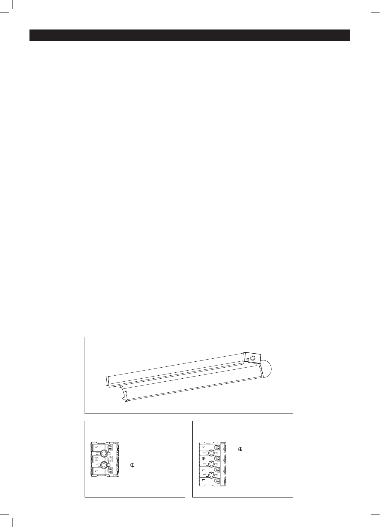
• Pressthelateralbuttonoftheluminairetoreleasethelens,whichwillswingandbehangingbyitshinge(SeeFig1).
For Surface Mounting (ceiling and walls):
• Markthexingpointsonthesubstrate,aligningthecableadequatelyinoneoftheexistingentries.
• Passthecablethroughtheentry.
• Fixtheluminairetothesubstrateusingadequatexingdevices,sotheluminairebodyissecurelyattachedtothesubstrate.
For BESA Box Mounting (ceiling and walls):
• Using1ofthe3BESAboxentries,aligningthecableadequatelyinoneoftheexistingentries.
• Passthecablethroughtheentry.
• FixtheluminairetotheBESAboxusingadequatexingdevices,sotheluminairebodyissecurelyattachedtothesubstrate.
• Ifneeded,useadditionalxingpointsdirectlytothesubstrateusingadequatexingdevices,sotheluminairebodyissecurelyattached
tothesubstrate.
For Pendant Mounting:
• UsingtheAccessoryILBTCSK058,xitadequatelytothesubstrate.
• Fixtheotherextremetotheluminairebody.
• Adjusttheluminaireheighttothenalposition.
For Conduit Mounting - Lateral:
• Knocktheplasticentriestobeused.
• FixtheluminairetothesubstrateasindicatedinSurfaceMounting,aligningtheconduit(s)totheentrytobeused.
• Fixtheconduittotheluminaire.
For Conduit Mounting - Upper Entry:
• Fixtheluminairetoconduitusingtheuppercentralentry.
• Useadequatemeanstoxtheluminairetotheconduitsoitcanbesecurelyfastened.
• Isrecommendedtouseanadditionalsafetywire(notsupplied)fromanadequatepositiononluminairetoanotherxingpoint.
Aftertheluminairebodyisxed,connectthemainssupplycabletotheterminals,payingattentiontothecablepolarity:L–Live(Brown),
N–Neutral(Blue),–Earth(Yellow/Green)–SeeFig2.ForEmergencyversions,additionallytoL,NandEarth,connecttheL1–SwitchLive
cable–SeeFig3.
TheterminalsuppliedallowsLoop-in/Loop-outwiring.Ifusingthisfeature,maximumWattageonasinglecircuitis650W.
Swingthelensandgentlypressbothendsagainsttheluminairebody,untilitclicks.
Fig 1.
Fig 2.
Connectthemainscable
totheterminal
N-BLUE
-YELLOW/GREEN
L-BROWN
Terminalprovidedallows
loop-in/loop-out
N-BLUE
-YELLOW/GREEN
L-BROWN
L1-SWITCHLIVE
Fig 3.
1

Emergency Operation
Theemergencybattenscanbeoperatedinmaintainedornon-maintainedmode.
1. Theluminairedelivers230lumensinEmergencymode.
2. Ensuretheemergencybatteryisconnectedtotheconnectorontheemergencydriver.
3. EnsurethestatusLEDandmanualtestbuttonconnectorareconnectedtotheemergencydriver.
For maintained operation:
• ConnecttheLivecable(Brown)toterminal(L).
• ConnecttheSwitchLivecabletoterminal(L1).
For non-maintained operation:
• ConnecttheLivecable(Brown)toterminal(L).
• Leaveterminal(L1)disconnected.
4. Whenpoweredon,thegreenLEDindicatorwillilluminateindicatingthatthebatteryisbeingcharged.
5. Tocheckthattheemergencyfunctionisworking,presstheredtestbuttonatanytimeandthebattenshouldilluminateinemergencymode.
6. Onfailureofthepermanentmainssupplythettingwillswitchautomaticallyfrombatterychargingtobatterydischargepoweringthe
LEDbatten.
7. Thisluminaireisdesignedtoprovide3hrsofemergencylightfollowingapowerfailure.Pleaseallowafull24hourchargebefore
carryinga3hourtestandmarktheinstallationdateontheLEDbattenlabel.
8. Thisluminairecontainsa6.4VV1500mAhLi-ionbattery.ForreplacementpleasecontactIntegral-LED.com
9. PleasendTestingSchedulelogattheendofthisinstallationguide.
Sensor Operation
Lightspanbattensarettedwithanoptionalsensor,thisturnsthebattenonwhenthelightlevelreachesthespeciedlevel.Settingsare
madebysettingdipswitchesonthesensorwhichislocatedinsidethebodyofthetting,pleaseopenthettingsaspertheinstructions
aboveandsetthedipswitchesinlinewiththetablebelow,thankyou.
Features:
• On-Ofunction
• Stand-bypower≤0.5W
• Slimdesign
• Smallsensorheadcanreducetheshadowofthelight
• Detectionarea,holdtimeanddaylightthresholdcanbepreciselysetbyDIPswitch
Sensor Specication
Input InputVoltage 198-264VAC50Hz
RatedInputVoltage 220-240VAC50Hz
Stand-byPower ≤0.5W
Output LoadPower 250W(Inductive)500WResistive)
HoldTime 5s/30s/90s/3min/20min/30min
SensorParameters SensingRange 100%/75%/50%/25%
DaylightSensor Disable/50Lux/30Lux/10Lux/2Lux
MountingHeight CeilingMounting:3-6m
DetectionArea Walking0.5-1m/skeepwalking≥2mwalk&stop≥5m
WirelessParameters Operatingfrequency 5.8GHz±75MHz
Dimmingcontrol 0N/0FF
Operatingtemperature -25°C-+60°C
OperatingEnvironment Safety&EMC EN55015
Certicaterequirement EMCTUV
Wiringmethod Pushterminal(4)
Others IPrating IP20(Built-in)
ProtectionClass Class II
InstallationSize 168*21*28mm
Packagingrequirement Clapboard+OuterCarton(K=A)
Life 50000h

Detection Area
Range DipSwitch1 DipSwitch2
100% ON ON
75% ON OFF
50% OFF ON
25% OFF OFF
Hold Time
Time DipSwitch3 DipSwitch4 DipSwitch5
5Seconds ON ON ON
30Seconds ON ON OFF
1Minute ON OFF ON
3Minutes ON OFF OFF
5Minutes OFF ON ON
10Minutes OFF ON OFF
20Minutes OFF OFF ON
30Minutes OFF OFF OFF
Daylight Sensor
LightLevel DipSwitch6 DipSwitch7 DipSwitch8
2LUX ON ON ON
10LUX ON ON OFF
25LUX OFF ON OFF
50LUX ON OFF OFF
DISABLE OFF OFF OFF
Warranty
Thisunitcarriesaveyearwarrantyfromdateofpurchase,providingithasbeeninstalledcorrectlyandnotmodiedinanyway.Should
afaultoccurpleasecontacttheoriginalpointofpurchase.
Important Notes
• Theluminairemustbeoperatedwithinthetemperaturerangedenedandavoidingextremehumidity.
• Operationmustbewithinratedvoltage.
• Keepawayfromstrongelectromagneticradiationsourcesandprotectfromlightningstrike.
• Shouldtheunitmalfunction,pleasereturnittothedistributororreseller,neverattemptrepairyourself.
• Donotinstalltheluminaireifanypartisbroken.Donotapplydirectpressuretothefrontlens.
• Theluminairemustbeinstalledbyaqualiedelectrician.
• Theluminaireshouldbepositionedawayfromheat,liquidandvibration.Ensurenocontactwithanycorrosivechemicals.
• Theluminaireshouldbemountedinfreeairandoperatedatanambienttemperatureof30degrees.
• Nevercovertheluminairewithanycoversorinsulationmaterials.
• Theluminaireshouldbepositionedatleast1mawayfromradiosasthismayaectthesignalreception.IP20ratedprotection.
Warranty/Technicalandcontactinformation
areallavailableat www.integral-led.com
Integral LED is a division of Integral Memory plc:
Unit6,IronBridgeClose,IronBridgeBusinessPark,
London,NW100UF,UK
WASTE ELECTRICAL PRODUCTS SHOULD NOT BE
DISPOSED OF WITH HOUSEHOLD WASTE. PLEASE
RECYCLE WHERE FACILITIES EXIST. CHECK WITH
YOUR LOCAL AUTHORITY FOR RECYCLING ADVICE.
Non-Dimmable
IP20
This manual suits for next models
11
Other Integral LED Lantern manuals


Popular Lantern manuals by other brands

Eaton
Eaton CrystalWay CGLine+ 40071354590 manual

ergoline
ergoline OPEN SUN 1050 ULTRA POWER operating instructions

Dale Tiffany
Dale Tiffany PG80516 Assembly instructions

ubbink
ubbink Multi Bright Float 3 LED manual

kenall
kenall SIMPLESEAL CDL6VL2 LED SERIES installation instructions

KingShield
KingShield ELTSLED65NM Installation & operating instructions

CLAYMORE
CLAYMORE 3FACE+ Series user manual

Visual Comfort & Co.
Visual Comfort & Co. Elsinore Bracket Lantern Assembly instructions

Maxim
Maxim Dover 56094 quick start guide

Philips
Philips SmartBirght BN013C Series Mounting instruction

Clas Ohlson
Clas Ohlson TN-G025W manual

Tracon Electric
Tracon Electric STLCAMP10W user manual


