Mitsubishi Q62DAN User manual

Digital-
A
nalog
Converter Module
User’s Manual
(Hardware)
Q62DAN
Q64DAN
Q68DAVN
Q68DAIN
Thank you for purchasing the Mitsubishi general-purpose
programmable controller MELSEC-Q Series
Prior to use, please read this manual thoroughly and familiarize
yourself with the product.
MODEL Q-D/A-N-U-H/W
MODEL
CODE 13JP80
IB(NA)-0800321-C(0808)MEE
2005 MITSUBISHI ELECTRIC CORPORATION

A
-1
DANGER
CAUTION
zSAFETY PRECAUTIONS z
(Always read these instructions before using the equipment.)
Before using this product, please read this manual and the relevant manuals
introduced in this manual carefully and pay full attention to safety to handle the
product correctly.
These instructions apply only to Mitsubishi equipment. Refer to the user’s manual
of the CPU module to use for a description of the programmable control system
safety instructions.
In this manual, the safety instructions are ranked as "DANGER" and "CAUTION".
Indicates that incorrect handling may cause hazardous
conditions, resulting in death or severe injury.
Indicates that incorrect handling may cause hazardous
conditions, resulting in medium or slight personal injury or
physical damage.
Note that the CAUTION level may lead to a serious consequence according
to the circumstances.
Always follow the instructions of both levels because they are important to
personal safety.
Please save this manual to make it accessible when required and always forward
it to the end user.
[Design Precautions]
CAUTION
zDo not bunch the control wires or communication cables with the main circuit
or power wires, or install them close to each other.
They should be installed 100 mm (3.94 inch) or more from each other.
Not doing so could result in noise that would cause erroneous operation.
zAt power ON/OFF, voltage or current may instantaneously be output from the
output terminal of this module. In such case, wait until the analog output
becomes stable to start controlling the external device.

A
-2
[Installation Precautions]
CAUTION
zUse the programmable controller in an environment that meets the general
specifications given in the User's Manual of the CPU module being used.
Using this programmable controller in an environment outside the range of
the general specifications could result in electric shock, fire, erroneous
operation, and damage to or deterioration of the product.
zWhile pressing the installation lever located at the bottom of module, insert
the module fixing tab into the fixing hole in the base unit until it stops. Then,
securely mount the module with the fixing hole as a supporting point.
Incorrect loading of the module can cause a malfunction, failure or drop.
When using the programmable controller in the environment of much
vibration, tighten the module with a screw.
zTighten the screw in the specified torque range.
Undertightening can cause a drop, short circuit or malfunction.
Overtightening can cause a drop, short circuit or malfunction due to damage
to the screw or module.
zCompletely turn off the externally supplied power used in the system before
mounting or removing the module.
Not doing so could result in damage to the product.
zDo not directly touch the module's conductive parts or electronic
components.
Touching the conductive parts could cause an operation failure or give
damage to the module.

A
-3
[Wiring Precautions]
CAUTION
zBe sure to ground the FG terminals to the protective ground conductor.
Not doing so could result in electric shock or erroneous operation.
zUse applicable solderless terminals and tighten with the specified torque. If
any solderless spade terminal is used, it may be disconnected when the
terminal screw comes loose, resulting in failure.
zWhen turning on the power supply or operating the module after installation
or wiring work, be sure that the module's terminal covers are correctly
attached.
Not attaching the terminal cover could result in electric shock.
zTighten the terminal screws with the specified torque.
If the terminal screws are loose, it could result in short circuits, fire, or
erroneous operation.
Tightening the terminal screws too far may cause damages to the screws
and/or the module, resulting in fallout, short circuits, or malfunction.
zBe sure there are no foreign substances such as sawdust or wiring debris
inside the module.
Such debris could cause fires, damage, or erroneous operation.
zThe module has an ingress prevention label on its top to prevent foreign
matter, such as wire offcuts, from entering the module during wiring.
Do not peel this label during wiring.
Before starting system operation, be sure to peel this label because of heat
dissipation.

A
-4
REVISIONS
The manual number is given on the bottom right of the top cover.
Print Date *Manual Number Revision
Aug.,2005 IB(NA)-0800321-A First edition
Jun.,2007 IB(NA)-0800321-B
Correction
Chapter 3, 6
Aug.,2008 IB(NA)-0800321-C
Correction
Compliance with the EMC and Low
Voltage Directives, Chapter 4
This manual confers no industrial property rights or any rights of any other kind, nor dose it
confer any patent licenses. Mitsubishi Electric Corporation cannot be held responsible for
any problems involving industrial property rights which may occur as a result of using the
contents noted in this manual.
2005 MITSUBISHI ELECTRIC CORPORATION

A
-5
CONTENTS
SAFETY PRECAUTIONS ...............................................................................A-1
REVISIONS ....................................................................................................A-3
CONTENTS....................................................................................................A-4
About the Manuals..........................................................................................A-4
Conformance to the EMC Directive/Low Voltage Directive .............................A-4
1. OVERVIEW ................................................................................................... 1
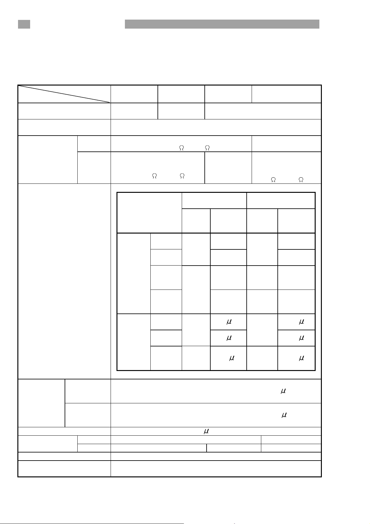
2. SPECIFICATIONS......................................................................................... 2
3. PART NAMES ............................................................................................... 4
4. HANDLING PRECAUTIONS.......................................................................... 6
5. WIRING ......................................................................................................... 6
5.1 Wiring Precautions ................................................................................... 6
5.2 External Wiring......................................................................................... 7
5.3 Switch setting for intelligent functional module ......................................... 9
6. EXTERNAL DIMENSIONS .......................................................................... 11
About Manual
The following manual is also related to this product.
In necessary, order it by quoting the details in the table below.
Related Manual
Manual Name Manual Number
(Model Code)
Digital-Analog Converter Module User's Manual
Q62DAN/Q64DAN/Q68DAVN/Q68DAIN/Q62DA/
Q64DA/Q68DAV/Q68DAI/GX Configurator-DA
(SW2D5C-QDAU-E)
SH-080054
(13JR02)
Compliance with the EMC and Low Voltage Directives
(1) For programmable controller system
To configure a system meeting the requirements of the EMC and Low
Voltage Directives when incorporating the Mitsubishi programmable
controller (EMC and Low Voltage Directives compliant) into other
machinery or equipment, refer to Chapter 9 "EMC AND LOW VOLTAGE
DIRECTIVES" of the QCPU User's Manual (Hardware Design,
Maintenance and Inspection).
The CE mark, indicating compliance with the EMC and Low Voltage
Directives, is printed on the rating plate of the programmable controller.
(2) For the product
For the compliance of this product with the EMC and Low Voltage
Directives,refer to Section 9.1.3 "Cables" in Chapter 9 "EMC AND LOW
VOLTAGE DIRECTIVES" of the QCPU User's Manual (Hardware Design,
Maintenance and Inspection).

1
1. Overview
This manual explains specifications and the names of the components for the
following modules which are used in combination with the MELSEC-Q Series CPU
module.
Q62DAN type digital-analog converter module (hereinafter referred to as the
Q62DAN)
Q64DAN type digital-analog converter module (hereinafter referred to as the
Q64DAN)
Q68DAVN type digital-analog converter module (hereinafter referred to as
the Q68DAVN)
Q68DAIN type digital-analog converter module (hereinafter referred to as the
Q68DAIN)
In this manual, the Q62DAN, Q64DAN, Q68DAVN and Q68DAIN are collectively
referred to as the D/A (Digital-Analog) converter modules.
After unpacking, confirm that the following products are enclosed.
Model code Product name Quantity
Q62DAN Q62DAN Model Digital-Analog Converter module 1
Q64DAN Q64DAN Model Digital-Analog Converter module 1
Q68DAVN Model Digital-Analog Converter module 1
Q68DAVN FG terminal L-Shaped metal fitting 1
Q68DAIN Model Digital-Analog Converter module 1
Q68DAIN FG terminal L-Shaped metal fitting 1

2
2. Specifications
The specifications for the D/A converter module are shown in the following table.
For general specifications, refer to the operation manual for the CPU module being
used.
Model name
Item Q62DAN Q64DAN Q68DAVN Q68DAIN
Number of analog output
points
2 points
(2 channels)
4 points
(4 channels)
8 points
(8 channels)
Digital input 16-bit signed binary (normal resolution mode: -4096 to 4095,
high resolution mode: -12288 to 12287, -16384 to 16383)
Voltage –10 to 10 V DC (External load resistance
value: 1 k to 1M ) —
Analog output
Current
0 to 20 mA DC
(External load resistance
value: 0 to 600 )
—
0 to 20 mA DC
(External load
resistance value:
0to 600 )
Normal resolution
mode
High resolution
mode
Analog output
range Digital
input
value
Maximum
resolution
Digital
input
value
Maximum
resolution
0 to 5V 1.25 mV 0.416
mV
1 to 5V
0 to
4000 1.0 mV
0 to
12000 0.333
mV
-10 to
10V 2.5 mV
-16000
to
16000
0.625
mV
Voltage
User
range
setting
-4000
to
4000 0.75 mV
-12000
to
12000
0.333
mV
0 to
20 mA 5 A 1.66 A
4 to
20 mA
0 to
4000 4 A
0 to
12000 1.33 A
Current
User
range
setting
-4000
to
4000
1.5 A
-12000
to
12000
0.83 A
xI/O characteristics,
Maximum resolution
Ambient
temperature
25 ± 5 °C
Within ± 0.1 % (Voltage: ±10 mV, Current: ± 20 A)
Accuracy
(Accuracy in
respect to
maximum
analog
output value)
Ambient
temperature
0 to 55 °C
Within ± 0.3 % (Voltage: ± 30 mV, Current: ± 60 A)
Conversion speed 80 s/channel
Voltage ± 12 V —Absolute
maximum output Current 21 mA — 21 mA
E2PROM write count Max. 100 thousand times
Output short circuit
protection Available

3
Model name
Item Q62DAN Q64DAN Q68DAVN Q68DAIN
Between the I/O terminal and programmable controller power supply
Insulation method
Between output channels
Between external supply power and analog output
: Photocoupler isolation
: No isolation
: Transformer isolation
Between the I/O terminal and programmable controller power supply
Dielectric withstand
voltage
Between external supply power and analog output
: 500VAC for 1 minute
Between the I/O terminal and programmable controller power supply
Insulation resistance
Between external supply power and analog output
: 500VDC 20M or more
I/O occupied points 16 points (I/O assignment: Intelligent 16 points)
Connected terminals 18-points terminal block
Applicable wire size 0.3 to 0.75 mm2
Applicable solderless
terminal
R1.25-3
(A solderless terminal with sleeve
cannot be used)
FG terminal:
R1.25-3, 1.25-YS3, RAV1.25-3,
V1.25-YS3A
Other terminals than FG:
R1.25-3 (A solderless terminal
with sleeve cannot be used)
24 V DC + 20 %, – 15 %
Ripple, spike 500 mV p-p or less
Inrush current:
2.5 A,
within 250 s
Inrush current:
2.5 A,
within 260 s
Inrush current:
2.5 A,
within 230 s
Inrush current:
2.5 A,
within 230 s
External supply power
0.15 A 0.24 A 0.20 A 0.27 A
Internal current
consumption (5 V DC) 0.33 A 0.34 A 0.38 A 0.38 A
Weight 0.19 kg 0.20 kg 0.20 kg 0.20 kg

4
3. Part Names
This section explains the names of the components for the D/A conversion
module.
Signal nameTerminal
number Q62DAN Q64DAN
1 V+ V+
2 COM COM
3
CH1
I+
CH1
I+
4 Vacant Vacant
5 V+ V+
6 COM COM
7
CH2
I+
CH2
I+
8 Vacant Vacant
9 Vacant V+
10 Vacant COM
11 Vacant
CH3
I+
12 Vacant Vacant
13 Vacant V+
14 Vacant COM
15 Vacant
CH4
I+
16 24 V
17 24 G
ERROR
IN 24VDC
RUN
Q6 DAN
(FG)
0 20mA
D/A
-10 10V
18
17
16
15
14
13
12
11
10
9
8
5
6
7
4
1
2
3
1)
2)
3)
18 FG
Signal nameTerminal
number Q68DAVN Q68DAIN
1 V+ I+
2 CH1 COM CH1 COM
3 V+ I+
4 CH2 COM CH2 COM
5 V+ I+
6 CH3 COM CH3 COM
7 V+ I+
8 CH4 COM CH4 COM
9 V+ I+
10 CH5 COM CH5 COM
11 V+ I+
12 CH6 COM CH6 COM
13 V+ I+
14 CH7 COM CH7 COM
15 V+ I+
16 CH8 COM CH8 COM
17 24 V
1)
2)
3)
Q68DA
RUN
ERROR
IN 24VDC
FG
1
2
3
4
5
6
7
8
9
10
11
12
13
14
15
16
17
18
4)
N
18 24 G

5
Number Name Description
1) RUN LED Displays the operating status of the D/A
converter module.
On : Normal operation
Flashing : During offset/gain setting mode
Off : 5V power switched off, watchdog
timer error occurred, or online module
change enabled
2) ERROR LED Displays the error status of the D/A converter
module.
On : Error
Off : Normal operation
Flashing : Error in switch settings
Switch No. 5 of the intelligent function
module has been set to a value other
than "0".
3) External power
supply terminal
This is the terminal for connecting the 24 V DC
external power supply.
4) FG terminal Frame ground terminal

6
4. Handling Precautions
(1)Do not drop the module case or subject it to heavy impact.
(2) Do not remove the PCB of the module from its case. Doing so may cause
the module to fail.
(3) Be careful not to let foreign particles such as swarf or wire chips enter the
module. They may cause a fire, mechanical failure or malfunction.
(4) The top surface of the module is covered with a protective film to prevent
foreign objects such as wire burrs from entering the module during wiring.
Do not remove this film until the wiring is complete. Before operating the
system, be sure to remove the film to provide adequate heat ventilation.
(5) Tighten the screws such as module fixing screws within the following
ranges.
Loose screws may cause short circuits, failures, or malfunctions.
Screw location Tightening torque
range
Module fixing screw (M3 screw) *1 0.36 to 0.48 N·m
Terminal block screw (M3 screw) 0.42 to 0.58 N·m
Terminal block mounting screw (M3.5 screw) 0.66 to 0.89 N·m
FG terminal screw (M3 screw) *2 0.42 to 0.58 N·m
*1: The module can be easily fixed onto the base unit using the hook at the
top of the module.
However, it is recommended to secure the module with the module
fixing screw if the module is subject to significant vibration.
*2: Q68DAVN, Q68DAIN only
5. Wiring
5.1 Wiring precautions
In order to optimize the functions of the D/A converter module and ensure system
reliability, external wiring that is protected from noise is required.
Please observe the following precautions for external wiring:
(1) Use separate cables for the AC control circuit and the external input signals
of the D/A converter module to avoid the influence of the AC side surges
and inductions.
(2) Do not mount the cables close to or bundle them with the main circuit line, a
high-voltage cable or a load cable from other than the programmable
controller. This may increase the effects of noise, surges and induction.
(3) Perform a one-point grounding for shielded lines and the shields of sealed
cables.
(4) A solderless terminal with insulating sleeve cannot be used for the terminal
block. Covering the cable- connection portion of the solderless terminal
with a marked tube or an insulation tube is recommended.

7
Point
When using Q68DAVN or Q68DAIN, If it is difficult to wire FG terminals due to
the limited installation space, use FG terminal L-shaped metal fitting.
5.2 External wiring
(1) For Q62DAN or Q64DAN
(a) For voltage output
1 k
1 M
D/A
conversion V+
COM
*1 *2 Motor drive module, etc.
GND
DC/DC
converter
24V
24G
FG
24 V DC
Filter
to
(b) For current output
0
600
D/A
conversion I+
COM
*1 *2 Motor drive module, etc.
GND
DC/DC
converter
24V
24G
FG
24 V DC
Filter
to
*1 Use a twisted two core shielded wire for the power wire.
*2 If there is noise or ripples in the external wiring, connect a 0.1 to
0.47 F25V capacitor between the V+/I+ terminal and COM.

8
(2) For Q68DAVN
1 k
1 M
D/A
conversion V+
COM
*1 *2 Motor drive module, etc.
GND
DC/DC
converter
24V
24G
FG
24 V DC
Filter
to
(3) For Q68DAIN
0
600
D/A
conversion I+
COM
*1 *2 Motor drive module, etc.
GND
DC/DC
converter
24V
24G
FG
24 V DC
Filter
to
*1 Use a twisted two core shielded wire for the power wire.
*2 If there is noise or ripples in the external wiring, connect a 0.1 to
0.47 F25V capacitor between the V+/I+ terminal and COM.

9
5.3 Switch setting for intelligent functional module
The settings for the intelligent function module are performed using the I/O
allocation settings for the GX Developer. When the intelligent function module
switches are not set, the default value for switches 1 to 5 is 0.
Setting item
Analog output range Output range
setting value
4 to 20 mA 0H*1
Switch 1
Output range setting
(CH1 to CH4)
H
CH4CH3CH2CH1 0 to 20 mA 1H
1 to 5 V 2H
0 to 5 V 3H
– 10 to 10 V 4H
User range setting FH
Switch 2
Output range setting
(CH5 to CH8)
H
CH8CH7CH6CH5
For Q62DAN and Q64DAN
H
CH4CH3CH2CH1
HOLD/CLEAR function setting
0H: CLEAR
1 to FH
(numeric value other than 0H)*
: HOLD
Switch 3
For Q68DAVN and Q68DAIN
CH8CH7CH6CH5CH4CH3CH2CH1
b7 b6 b5 b4 b3 b2 b1 b0b8
0
b15
0to
HOLD/CLEAR function setting
0 : CLEAR
1 : HOLD
Switch 4
H
00H
01 to FFH(numeric
value other than 00H)*
: Normal mode (non-synchronized)
: Synchronized output mode
0H
1 to FH(numeric
value other than 0H)*
: Normal mode (D/A conversion processing)
: Offset/gain setting mode
0H
1 to FH(numeric
value other than 0H)*
: Normal resolution mode
: High resolution mode
Switch 5 0 : Fixed
* Setting any value within the setting range will provide the same operation.
When the setting range is 1 to FH, set 1 for example.

10
Point
(1) Depending on the type of module used, the settings for D/A module output
range are shown below.
• Q62DAN, Q64DAN .....0Hto 4H, FH
• Q68DAVN...................0H, 2Hto 4H, FH
1: When the setting is 0H, the output operating
range swill be 1 to 5 V.
• Q68DAIN ....................0H, 1H, FH
(2) For Q62DAN and Q64DAN, leave the switch 2 vacant.
(3) For Q68DAVN and Q68DAIN, the switch 3 will set in binary.
Setting will be easy if the input format is changed to binary number.
Example) For setting CH3, CH5 and CH8 to HOLD.
Input format Binary Hexadecimal
Setting value 10010100 94 H
(4) If the offset/gain setting mode is set using intelligent function module
switch 4, other settings by switch 4 (settings for resolution mode and
synchronous output mode) will be ignored.
(5) Perform the offset/gain settings after checking the RUN LED flashes in
offset/gain setting mode. If the RUN LED does not flash, check to see if the
switch 4 setting is correct.
(6) Since the analog output value will differ considerably, depending on the
resolution mode setting, thoroughly check the settings for the intelligent
function module switches before performing the analog output processing.
Example) Analog output value when the setting range is -10 to 10V and
the digital input value is set to 4000.
High resolution
mode
Normal resolution
mode
Analog output value About 2.5 V About 10.0 V

11
6. External Dimensions
(1) Q62DAN
90 (3.54)
98 (3.86)
ERROR
RUN
Q62DAN
27.4 (1.08)
1
2
3
4
5
6
7
8
9
10
11
12
13
14
15
16
17
18
112 (4.41)
Unit: mm (inch)
(2) Q64DAN
90 (3.54)
98 (3.86)
27.4 (1.08)
112 (4.41)
Q64DAN
RUN
IN 24VDC
ERROR
9
8
5
6
7
4
1
2
3
18
17
16
15
14
13
12
11
10
C
H
1I+
V+
COM
C
H
2I+
V+
COM
C
H
3I+
V+
COM
C
H
4I+
V+
COM
(FG)
0 20mA
D/A
-10 10V
Unit: mm (inch)

12
(3) Q68DAVN
ERROR
RUN
Q68DAVN
90 (3.54)
98 (3.86)
63 (2.48)
9.5
112 (4.41)
71.5 (2.81)
27.4 (1.08)
1
2
3
4
5
6
7
8
9
10
11
12
13
14
15
16
17
18
M3 screw (Accessory) M3 screw (Accessory)
FG terminal L-Shaped metal fitting
(Accessory)
(0.37)
Unit: mm (inch)
(4) Q68DAIN
90 (3.54)
98 (3.86)
9.5
112 (4.41) 27.4 (1.08)
FG
ERROR
RUN
Q68DAIN
C
H
8
C
H
7
C
H
6
C
H
5
C
H
4
C
H
3
C
H
2
I+
COM
I+
COM
I+
COM
I+
COM
I+
I+
COM
COM
C
H
1
COM
I+
I+
COM
IN24VDC
1
2
3
4
5
6
7
8
9
10
11
12
13
14
15
16
17
18
M3 screw (Accessory) M3 screw (Accessory)
63 (2.48)
71.5 (2.81)
FG terminal L-Shaped metal fitting
(Accessory)
(0.37)
Unit: mm (inch)

13
MEMO

Warranty
Mitsubishi will not be held liable for damage caused by factors found not to be the cause of
Mitsubishi; machine damage or lost profits caused by faults in the Mitsubishi products;
damage, secondary damage, accident compensation caused by special factors unpredictable
by Mitsubishi; damages to products other than Mitsubishi products; and to other duties.
For safe use
yThis product has been manufactured as a general-purpose part for general industries, and
has not been designed or manufactured to be incorporated in a device or system used in
purposes related to human life.
yBefore using the product for special purposes such as nuclear power, electric power,
aerospace, medicine or passenger movement vehicles, consult with Mitsubishi.
yThis product has been manufactured under strict quality control. However, when installing
the product where major accidents or losses could occur if the product fails, install
appropriate backup or failsafe functions in the system.
U.S.A Mitsubishi Electric Automation Inc.
500 Corporate Woods Parkway Vernon
Hills, IL 60061, U.S.A.
Tel : +1-847-478-2100
Brazil MELCO-TEC Rep. Com.e Assessoria
Tecnica Ltda.
Rua Correia Dias, 184,
Edificio Paraiso Trade Center-8 andar
Paraiso, Sao Paulo, SP Brazil
Tel : +55-11-5908-8331
Germany Mitsubishi Electric Europe B.V. German
Branch
Gothaer Strasse 8 D-40880 Ratingen,
GERMANY
Tel : +49-2102-486-0
U.K Mitsubishi Electric Europe B.V. UK
Branch
Travellers Lane, Hatfield, Hertfordshire.,
AL10 8XB, U.K.
Tel : +44-1707-276100
Italy Mitsubishi Electric Europe B.V. Italian
Branch
Centro Dir. Colleoni, Pal. Perseo-Ingr.2
Via Paracelso 12, I-20041 Agrate Brianza.,
Milano, Italy
Tel : +39-039-60531
Spain Mitsubishi Electric Europe B.V. Spanish
Branch
Carretera de Rubi 76-80,
E-08190 Sant Cugat del Valles,
Barcelona, Spain
Tel : +34-93-565-3131
France Mitsubishi Electric Europe B.V. French
Branch
25, Boulevard des Bouvets, F-92741
Nanterre Cedex, France
TEL: +33-1-5568-5568
South Africa Circuit Breaker Industries Ltd.
Private Bag 2016, ZA-1600 Isando,
South Africa
Tel : +27-11-928-2000
Hong Kong Mitsubishi Electric Automation
(Hong Kong) Ltd.
10th Floor, Manulife Tower, 169 Electric
Road, North Point, Hong Kong
Tel : +852-2887-8870
China Mitsubishi Electric Automation
(Shanghai) Ltd.
4/F Zhi Fu Plazz, No.80 Xin Chang Road,
Shanghai 200003, China
Tel : +86-21-6120-0808
Taiwan Setsuyo Enterprise Co., Ltd.
6F No.105 Wu-Kung 3rd.Rd, Wu-Ku
Hsiang, Taipei Hsine, Taiwan
Tel : +886-2-2299-2499
Korea Mitsubishi Electric Automation Korea
Co., Ltd.
1480-6, Gayang-dong, Gangseo-ku
Seoul 157-200, Korea
Tel : +82-2-3660-9552
Singapore Mitsubishi Electric Asia Pte, Ltd.
307 Alexandra Road #05-01/02,
Mitsubishi Electric Building,
Singapore 159943
Tel : +65-6470-2460
Thailand Mitsubishi Electric Automation (Thailand)
Co., Ltd.
Bang-Chan Industrial Estate No.111
Moo 4, Serithai Rd, T.Kannayao,
A.Kannayao, Bangkok 10230 Thailand
Tel : +66-2-517-1326
Indonesia P.T. Autoteknindo Sumber Makmur
Muara Karang Selatan, Block A/Utara
No.1 Kav. No.11 Kawasan Industri
Pergudangan Jakarta - Utara 14440,
P.O.Box 5045 Jakarta, 11050 Indonesia
Tel : +62-21-6630833
India Messung Systems Pvt, Ltd.
Electronic Sadan NO:III Unit No15,
M.I.D.C Bhosari, Pune-411026, India
Tel : +91-20-2712-3130
Australia Mitsubishi Electric Australia Pty. Ltd.
348 Victoria Road, Rydalmere,
N.S.W 2116, Australia
Tel : +61-2-9684-7777
Country/Region Sales office/Tel
When exported from Japan, this manual does not require application to the Ministry
of Economy, Trade and Industry for service transaction permission.
Specifications subject to change without notice.
Printed in Japan on recycled paper.
HEAD OFFICE : TOKYO BUILDING, 2-7-3 MARUNOUCHI, CHIYODA-KU, TOKYO 100-8310, JAPAN
NAGOYA WORKS : 1-14, YADA-MINAMI 5-CHOME, HIGASHI-KU, NAGOYA, JAPAN
Country/Region Sales office/Tel
Other manuals for Q62DAN
2
This manual suits for next models
3
Table of contents
Other Mitsubishi Media Converter manuals

Mitsubishi
Mitsubishi Q66-AD-Dg User manual

Mitsubishi
Mitsubishi CP910E(ID) User manual

Mitsubishi
Mitsubishi AJ65SBT2B-64DA User manual

Mitsubishi
Mitsubishi AJ65SBT-62DA User manual

Mitsubishi
Mitsubishi P91W User manual

Mitsubishi
Mitsubishi PAC-SJ96MA-E User manual

Mitsubishi
Mitsubishi MELSEC A1S64AD User manual

Mitsubishi
Mitsubishi AJ65SBT-62DA User manual

Mitsubishi
Mitsubishi CP800E User manual

Mitsubishi
Mitsubishi MELSEC-A AJ65VBTCU-68DAVN User manual