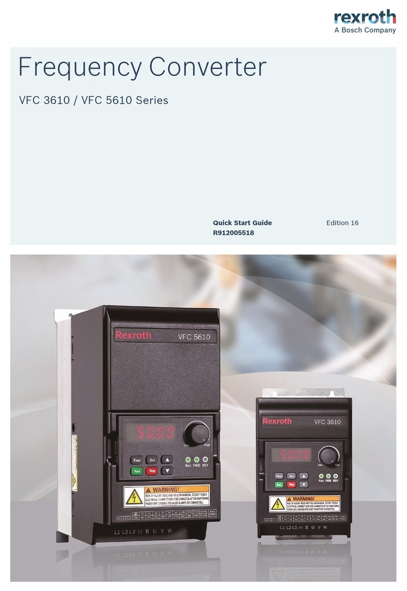
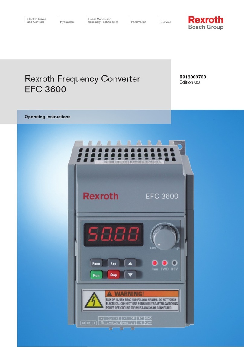
REXROTH Fe Series User manual

Rexroth Frequency Converter
The Drive & Control Company
Fe Series
Edition 04
Instruction Manual (Quick Start)
R912004884

Bosch Rexroth AG
Record of Revision
Edition Release Date Notes
DOK-RCON01-FE*********-IN02-EN-P 2013.11 First release
DOK-RCON01-FE*********-IN03-EN-P 2014.11 Added new functions
DOK-RCON01-FE*********-IN04-EN-P 2014.12 Firmware upgrade
About this Documentation
This Instruction Manual (Quick Start) is derived from the Instruction Manual
which includes the product data in details.
Never work with or control the product before reading through the Safety In-
structions in the standard delivery and the safety related chapters in the Instruc-
tion Manual.
Reference
For documentations available in other type or language, please consult your lo-
cal sales partner or check www.boschrexroth.com/fe.
Copyright
© Bosch Rexroth (Xi'an) Electric Drives and Controls Co., Ltd. 2014
This document, as well as the data, specifications and other information set
forth in it, are the exclusive property of Bosch Rexroth (Xi'an) Electric Drives
and Controls Co., Ltd. It may not be reproduced or given to third parties without
its consent.
Liability
The specified data is intended for product description purposes only and shall
not be deemed to be a guaranteed characteristic unless expressly stipulated in
the contract. All rights are reserved with respect to the content of this documen-
tation and the availability of the product.
RS-d3d2be50e50dd70b0a6846a500fcba27-3-en-US-4

Table of Contents
Page
1 Mechanical Installation.......................................................................... 1
1.1 Visual Check.......................................................................................... 1
1.2 Ambient Conditions............................................................................... 1
1.3 Installation Conditions........................................................................... 2
1.4 Dimensions............................................................................................ 3
2 Electric Installation................................................................................ 6
2.1 Cable Specifications.............................................................................. 6
2.2 Power Terminals.................................................................................. 10
2.3 Interface Connection for Signals......................................................... 12
3 Parameter Settings.............................................................................. 17
3.1 Operating Panel................................................................................... 17
3.2 Start-up................................................................................................ 18
3.3 Operating Descriptions........................................................................ 19
3.4 Parameters........................................................................................... 20
4 Error Indication.................................................................................... 26
Bosch Rexroth AG
Table of Contents
DOK-RCON01-FE*********-IN04-EN-P I

Bosch Rexroth AG
II DOK-RCON01-FE*********-IN04-EN-P

1 Mechanical Installation
1.1 Visual Check
After unpacking the frequency converter, perform a thorough visual check.
Check the following:
●Has the right device been supplied?
●Is the device damaged?
●Check the case for transport damage such as scratches, cracks or dents.
If you find a deviation from one of the above points, please contact your
Bosch Rexroth sales partner.
1.2 Ambient Conditions
If it is to function perfectly, the frequency converter must be installed in an envi-
ronment matching the data provided below.
Ambient temperature -10...+40 °C (No derating)
+40...+50 °C (Derating①)
Max. altitude Up to 1,000 m (No derating)
1,000...4,000 m (1 % / 100 m)
Relative humidity < 90 %
Degrees of protection IP 20 (Control cabinet mounting)
Tab. 1-1: Ambient conditions
①: See "9.2: Derating of Electrical Data" in the Instruction Manual.
Bosch Rexroth AG
Mechanical Installation
DOK-RCON01-FE*********-IN04-EN-P 1/31

1.3 Installation Conditions
Depending on rating, the frequency converters are available in different sizes. In
order not to affect device cooling, the frequency converter must always be in-
stalled upright. For perfect heat dissipation, the minimum installation spacing to
the devices shown in the drawing must be observed.
Fig. 1-1: Installation conditions
●The frequency converter shown above is Frame 1. The minimum
installation spacing stated applies to Frame 1 to Frame 7.
●The frequency converter must be vertically installed.
●If one frequency converter is arranged above another, make sure
the upper limit of air temperature into the inlet is not exceeded
(see chapter 1.2 "Ambient Conditions" on page 1). A baffle plate
is recommended between the frequency converters to prevent the
rising hot air being drawn into the upper frequency converter if
the upper limit of air temperature is exceeded.
Bosch Rexroth AG
Mechanical Installation
2/31 DOK-RCON01-FE*********-IN04-EN-P

1.4 Dimensions
Fe model Frame
Width Height Depth Mounting
hole
Net
weight
B/b H/h T Ø G m
[mm] [mm] [mm] [mm] [kg]
FECG02.1-0K75-...
1 125/109 220/204 176 6
3
FECG02.1-1K50-...
FECG02.1-2K20-... 3.2
FECG02.1-4K00-...
FECx02.1-5K50-... 3.5
FECx02.1-7K50-...
FECx02.1-11K0-... 2 220/180 392/372 218 9.5 10.7
FECx02.1-15K0-... 10.9
FECx02.1-18K5-... 3 275/200 463/443 218 9.5 16.2
FECx02.1-22K0-... 16.9
FECx02.1-30K0-... 4 290/200 574/550 236 11 21.5
FECx02.1-37K0-... 22
FECx02.1-45K0-... 5 364/260 602/576 260 11 33.2
FECx02.1-55K0-... 33.8
FECx02.1-75K0-... 6 455/375 682/650 290 11 50.9
FECx02.1-90K0-... 52.5
FECx02.1-110K-...
7 570/450 850/825 360 11
96.5
FECx02.1-132K-... 100
FECx02.1-160K-... 102
Tab. 1-2: Fe dimensions
"x" in Fe model "FECx..." is a substitute for G or P series.
Bosch Rexroth AG
Mechanical Installation
DOK-RCON01-FE*********-IN04-EN-P 3/31

Fig. 1-2: Frame 1
Fig. 1-3: Frame 2, 3, 4
Bosch Rexroth AG
Mechanical Installation
4/31 DOK-RCON01-FE*********-IN04-EN-P

Fig. 1-4: Frame 5, 6
Fig. 1-5: Frame 7
Bosch Rexroth AG
Mechanical Installation
DOK-RCON01-FE*********-IN04-EN-P 5/31

2 Electric Installation
2.1 Cable Specifications
2.1.1 Connecting to the Mains
Cable specification for international without USA / Canada
●ONLY USE copper wires of 90 ℃ or above with XLPE or EPR insu-
lation according to IEC 60364-5-52.
●It is recommended to use shielded cables to connect the motor.
●The specification is based on the supply voltage of 3P 380 VAC.
Fe
Model
Fuse
Power cables installation mode PE
B1 B2 E Torque / Screw Cable
size Torque /Screw
[A] [mm2] [mm2] [mm2][Nm / lb-in] (Mx) [mm2][Nm / lb-in]
(Mx)
0K75 10 1.5 1.5 1.5 1.8 (M4) 10 1.8 (M4)
1K50 10 1.5 1.5 1.5 1.8 (M4)) 10 1.8 (M4)
2K20 16 1.5 1.5 1.5 1.8 (M4) 10 1.8 (M4)
4K00 20 2.5 2.5 2.5 1.8 (M4) 10 1.8 (M4)
5K50 25 4 4 2.5 1.8 (M4) 10 1.8 (M4)
7K50 25 4 4 2.5 1.8 (M4) 10 1.8 (M4)
11K0 32 6 6 4 2...2.8 (M5) 10 2...2.8 (M5)
15K0 50 10 10 10 2...2.8 (M5) 10 2...2.8 (M5)
18K5 63 16 16 10 4...5 (M6) 16 4...5 (M6)
22K0 80 16 25 16 4...5 (M6) 16 4...5 (M6)
30K0 100 25 – 25 4...5 (M6) 16 4...5 (M6)
37K0 125 25 25 25 4...5 (M6) 16 6...9 (M8)
45K0 160 50 – 50 6...9 (M8) 25 6...9 (M8)
55K0 160 50 – 50 6...9 (M8) 25 15...20 (M10)
75K0 250 95/2*50 – 95/2*50 15...20 (M10) 50 15...20 (M10)
90K0 250 95/2*50 – 95/2*50 15...20 (M10) 50 15...20 (M10)
110K 315 – – 150/2*70 15...20 (M10) 95 15...20 (M10)
132K 315 – – 150/2*70 20 (M12) 120 15...20 (M10)
160K 400 – – 240 20 (M12) 120 15...20 (M10)
Tab. 2-1: Fuse and cable dimensions for international without USA / Canada
Bosch Rexroth AG
Electric Installation
6/31 DOK-RCON01-FE*********-IN04-EN-P

Cable specification for USA / Canada
●ONLY USE copper wires of 75 ℃ or above according to UL 508C.
●It is recommended to use shielded cables to connect the motor.
●The specification is based on the supply voltage of 3P 380 VAC.
●The cables connecting to PE terminal should assemble the UL cer-
tificated wire connector which has suitable rating for wire gauge!
Fe
Model
Fuse Power cables PE
Cable size Torque / Screw Cable size Torque / Screw
[A] [AWG] [Nm / lb-in] (Mx) [AWG] [Nm / lb-in] (Mx)
0K75 6 14 1.8 (M4) 8 1.8 (M4)
1K50 10 14 1.8 (M4)) 8 1.8 (M4)
2K20 15 14 1.8 (M4) 8 1.8 (M4)
4K00 25 10 1.8 (M4) 8 1.8 (M4)
5K50 30 10 1.8 (M4) 8 1.8 (M4)
7K50 40 10 1.8 (M4) 8 1.8 (M4)
11K0 50 6 2...2.8 (M5) 8 2...2.8 (M5)
15K0 60 6 2...2.8 (M5) 8 2...2.8 (M5)
18K5 80 4 4...5 (M6) 8 4...5 (M6)
22K0 80 4 4...5 (M6) 8 4...5 (M6)
30K0 100 3 4...5 (M6) 8 4...5 (M6)
37K0 125 3 4...5 (M6) 6 6...9 (M8)
45K0 150 2/0 6...9 (M8) 6 6...9 (M8)
55K0 175 2/0 6...9 (M8) 6 15...20 (M10)
75K0 225 4/0 15...20 (M10) 4 15...20 (M10)
90K0 250 4/0 15...20 (M10) 4 15...20 (M10)
110K 300 350 kcmil 15...20 (M10) 4 15...20 (M10)
132K 400 750 kcmil 20 (M12) 3 15...20 (M10)
160K 450 750 kcmil 20 (M12) 2 15...20 (M10)
Tab. 2-2: Fuse and cable dimensions for USA / Canada
Bosch Rexroth AG
Electric Installation
DOK-RCON01-FE*********-IN04-EN-P 7/31

2.1.2 Signal Connection
The following requirements apply for the signal connection wiring:
●flexible cables with wire end sleeves
●cable cross-section: 0.3...1.0 mm2
●cable length: max. 20 m
●analog inputs ±10 V, VR1, VR2, +I and GND: use shielded cables
●analog inputs +I and GND: to eliminate interference from external influences,
connect +I and GND on the transducer with a 22 nF capacitor (50 V) and run
the signal cable two or three times through a ferrite ring.
Bosch Rexroth AG
Electric Installation
8/31 DOK-RCON01-FE*********-IN04-EN-P

2.1.3 Overview of Electric Connections
Fig. 2-1: Block diagram
Fe up to 15K0 have internal brake choppers.
Bosch Rexroth AG
Electric Installation
DOK-RCON01-FE*********-IN04-EN-P 9/31

2.2 Power Terminals
The table below describes the symbols on the frequency converter's power con-
nection terminals and their function.
Terminal Description
L1, L2, L3 Mains power supply inputs
U, V, W Frequency converter outputs (to be connected to the motor)
PB Reserved terminal for external brake resistor (applicable to 0K75...15K0 frequency
converters)
P1, (+) DC positive bus outputs
(–) DC negative bus output
Grounding
Tab. 2-3: Power terminals description
Depending on size, the position and sequence of the power terminals on the in-
dividual frequency converter may differ. Refer to the graphics below for the ex-
act connection terminal position and sequence.
Applicable to 0K75...7K50
Fig. 2-2: Power terminals_Frame 1_Top
Fig. 2-3: Power terminals_Frame 1_Bottom
Applicable to 11K0...15K0
Fig. 2-4: Power terminals_Frame 2
Bosch Rexroth AG
Electric Installation
10/31 DOK-RCON01-FE*********-IN04-EN-P

Applicable to 18K5...37K0
Fig. 2-5: Power terminals_Frame 3, 4
Applicable to 45K0...90K0
Fig. 2-6: Power terminals_Frame 5, 6
Applicable to 110K
Fig. 2-7: Power terminals_Frame 7 (110K)
Applicable to 132K...160K
Fig. 2-8: Power terminals_Frame 7 (132K, 160K)
1. For 11K0...160K, the main circuit terminals are on the bottom
of the frequency converters.
2. For 45K0...160K, UL marked connectors and cables should be
used for wiring of the terminal blocks. The connectors may be
of crimp, ring or fork types or other similar types.
3. There are two grounding connections, one for the input side,
the other for the output side.
Bosch Rexroth AG
Electric Installation
DOK-RCON01-FE*********-IN04-EN-P 11/31

2.3 Interface Connection for Signals
2.3.1 Jumper Wiring
Fig. 2-9: Jumper description
Shown above are factory defaults.
2.3.2 Communication Port
Fig. 2-10: RS485 communication port
●Crimp terminal wiring range: AWG 22...AWG 12
●Crimp terminal wire type: 75 ℃ and above copper only
●Crimp terminal torque: 5 kgf-cm (4.3 In-ibf)
Bosch Rexroth AG
Electric Installation
12/31 DOK-RCON01-FE*********-IN04-EN-P

2.3.3 NPN/ PNP Mode Selection
Jumper SW
Fig. 2-11: NPN/PNP Jumper SW
As shown in the figure above, the factory default setting of the jump-
er is NPN.
Jumper SW determines:
1. The internal 24 V power supply or an external 24 V power supply.
2. The inputs are activated by connection of 24 V to an input (PNP/ active in-
put) or connection of 0 V to an input (NPN/ passive input).
2.3.4 Analog Input Terminal (+10 V, VRC, GND, +I)
Fig. 2-12: Analog input terminal
Bosch Rexroth AG
Electric Installation
DOK-RCON01-FE*********-IN04-EN-P 13/31

1. For connection of low level analog signals, which are easily af-
fected by external interference, the wiring length should be as
short as possible (less than 20 m), shielded cables must be
used.
2. Incorrect operation may occur due to interference on the ana-
log signal. In such cases, connect a capacitor and ferrite core at
the output side of the analog signal, as shown above.
2.3.5 Control Circuit Terminals
Control circuit terminals figure
Fig. 2-13: Control circuit terminals
Applicable to 0K75...160K CPU board.
Control circuit terminals description
Terminal Signal function Description Signal requirement
SF Forward/stop See parameters b00 and E38
Opto-electronic coupler isolated
input, 24 VDC for external power
supply
NPN/PNP modes, see fig. 2-11
"NPN/PNP Jumper SW" on page
13 for details
SR Reverse/stop See parameters b00 and E38
RST Error reset "Connected" for reset
E-Stop External abnormality in-
put
[E32] = 0: "Connected",
coasting to stop
[E32] = 1, "Disconnected",
coasting to stop
X1
X2
X3
Multi-function inputs See parameters b00, b34,
b35, b45, E39, H07 and H23
SC Shared connection for
digital signals
Shared connection for SF\SR
\RST\E-Stop\X1...X3
Tab. 2-4: Digital inputs
Bosch Rexroth AG
Electric Installation
14/31 DOK-RCON01-FE*********-IN04-EN-P

Terminal Signal function Description Signal requirement
FB Feedback input signal Feedback signal, analog volt-
age input
Input voltage range: 0...5 V
Input resistance: 100 kΩ
Resolution: 1:1000
+10V Power supply terminal for
speed commands
Power supply for speed com-
mands 10 V (max. current 10 mA)
VRC
Frequency commands
Analog voltage frequency
command
JP5, position 2-3
Input voltage range: 0...10 V
Input resistance: 100 kΩ
Resolution: 1:2000
JP5, position 1-2
Input voltage range: 0...5 V
Input resistance: 50 kΩ
Resolution: 1:2000
+I Analog current frequency
feedback signal
Input current range: 4...20 mA
Input resistance: 165 Ω
Resolution: 1:1000
GND Analog common terminal Isolated from COM −
Tab. 2-5: Analog inputs
Terminal Signal function Description Signal requirement
OUT1 Open collector output 1 Programmable digital output
with multiple functions. See
parameters E16, E17 for de-
tails Open collector outputs isolated
via opto-electronic couplers:
Max. output voltage: +24 VDC
Max. output current: 50 mA
OUT2 Open collector output 2
CME Common terminal for
OUT1 and OUT2
For internal 24 V power sup-
ply: to be short circuited to
the COM terminal
For external power supply: to
be short circuited to the
“earth” of the power supply.
DO-COM Pulse output
Programmable to be pulse
output with multiple func-
tions. See parameters E09
for details.
Open collector outputs isolated
via opto-electronic couplers:
Output frequency: depends on
E10, max. 50.0 kHz
Max. output voltage: 24 VDC
Bosch Rexroth AG
Electric Installation
DOK-RCON01-FE*********-IN04-EN-P 15/31

Terminal Signal function Description Signal requirement
Ta Relay Ry output Ta-Tb: N.O.; Tb-Tc: N.C. (Tb is
the common terminal)
Programmable relay output
with multiple functions. See
parameter E18
Contact transmitter capacity:
250 VAC, 3 A or lower
30 VDC, 3 A or lower
Tc
Tb Relay output common ter-
minal
+24 V Anode 24 VDC COM (Cathode) −
Tab. 2-6: Digital outputs
Terminal Signal function Description Signal requirement
FM1-GND Analog multi- function
output 1 Programmable analog output
with multiple functions. See
parameters E04...E08 for de-
tails.
Output voltage/current settable
via JP3, JP4 for FM1, FM2:
Voltage signal range: 0/2...10 V
Current signal range: 0/4...20
mA
FM2-GND Analog multi- function
output 2
Tab. 2-7: Analog outputs
Terminal Signal function Description Signal requirement
PGP-COM Supply voltage nonbreak
function Power supply for the encoder Max. output current: 100 mA
A+ Encoder signal A JP2, position 2-3: select en-
coder differential inputs from
A+, A-, B+ and B-
JP2, position 1-2: select
open collector inputs from A-,
B-
Encoder voltage range for differ-
ential input:
+8...24 V
Max. input frequency: 200.0 kHz
A-
B+
Encoder signal B
B-
Tab. 2-8: Encoder signal
Terminal Signal function Description Signal requirement
485+ Positive terminal for dif-
ferential signal RS485 Standard 485 communication port. Use twisted pair or shielded
cables. RJ11 port and 2 PIN crimp terminals are optional. Both
connections are connected internally with the same 485 port
(parallel mode).
485- Negative terminal for dif-
ferential signal RS485
Tab. 2-9: Communication
Bosch Rexroth AG
Electric Installation
16/31 DOK-RCON01-FE*********-IN04-EN-P
Other manuals for Fe Series
1
This manual suits for next models
19
Table of contents
Other REXROTH Media Converter manuals