- 3 -
TESTING (Continued)
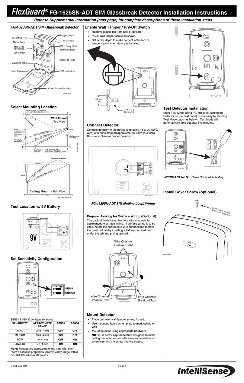
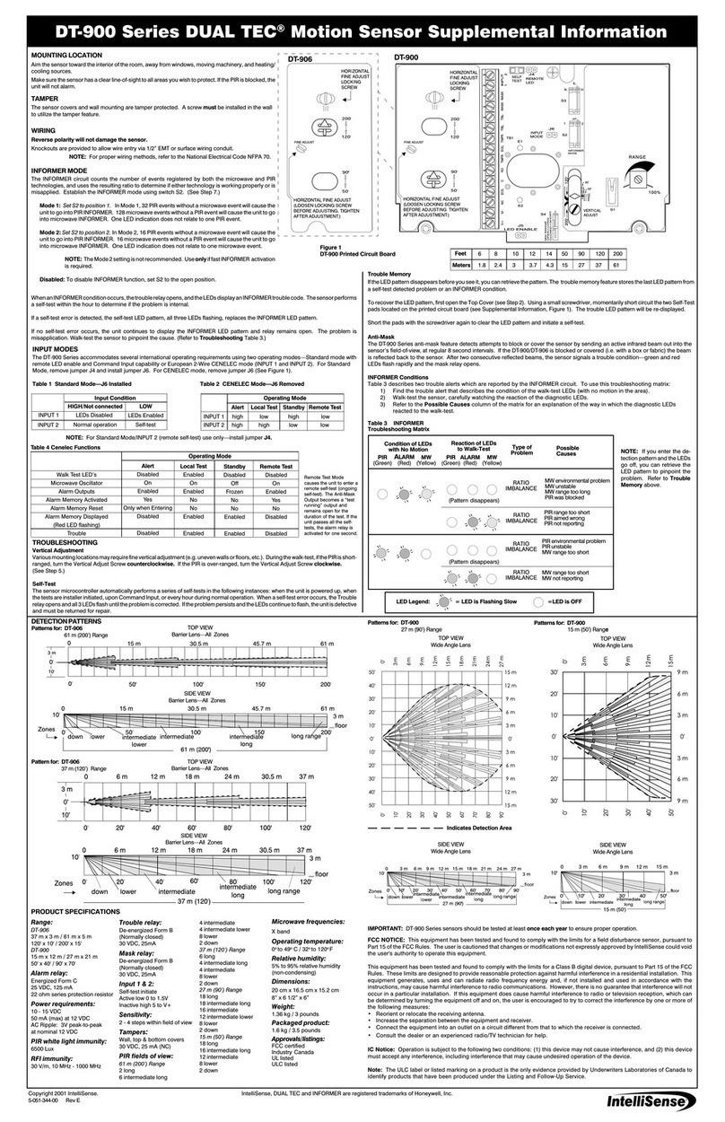
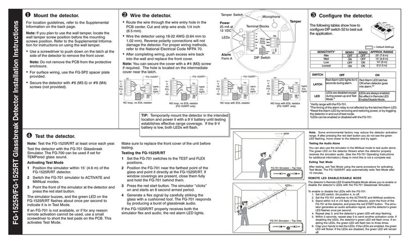
IMPORTANT: Some environmental factors may reduce the detector
activation range. If you do not see the green LED flashing after pressing
the red start button, move closer to the detector and try again.
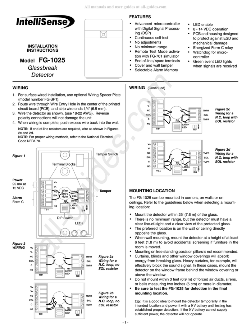
Figure 7
ed Start
Button
After testing, exit the Test Mode using the same procedure for
activating the Test Mode. The FG-1025 also will automatically
exit Test Mode after ten minutes.
LED Indicators:
The two LEDs on the front cover are used to indicate the
detector's operational status. The following table summarizes
the LED operation when the LEDs are enabled.
APPLICATIONS INFORMATION
The FG-1025 is designed to detect framed glass broken by an
impact sufficient to make a hole.
NOTE: The FG-1025 detects shattering of framed glass by a
direct impact. It may not consistently detect breakage by blows
that only crack the glass, by high velocity projectiles (such as
bullets) or if the glass is broken without an impact.
To minimize the chance of false alarms:
Do not use outside.
Avoid installing in rooms with high-level noise sources, such
as air compressors, bells, power tools, etc., if those sources
can be active when the detector can signal an alarm.
Test false alarm immunity by activating any known noise
sources in the room.
To maximize detection:
Mount the detector on a wall or ceiling directly opposite the
glass if possible. The least desirable mounting location is on
the same wall as the glass.
Minimize range to the glass. Do not install beyond the
maximum specified range even if testing indicates greater
range.
Verify all installations back to the panel to be sure that the
protection loop is intact.
Figure 6
ed Start
Button
If an FG-701 is not available, or if for any reason remote activa-
tion cannot be used, use a screwdriver to short the test pads at
location S3 on the PCB (see Figure 1). This will activate Test
Mode. Make sure to close the front cover of the FG-1025 before
beginning test.
To test the FG-1025:
1. Place the detector in Test Mode as described above.
2. Set the FG-701 switches to the TEST and FLEX positions.
3. Press the red start button. The simulator will "click" on and
start an eight second armed period.
4. Position the FG-701 near the farthest point of the protected
glass and point it directly at the FG-1025.
5. Generate a flex signal by carefully striking the glass with a
cushioned tool. The FG-701 will respond by producing a
burst of glass break audio. ( efer to Figure 7.)
If both the flex and audio are received properly, the red alarm
LED on the FG-1025 will light.
IMPORTANT: If window coverings are present, close them fully and
hold the FG-701 behind the window coverings for testing.
NOTE: You can also use the simulator in the MANual mode to test
audio alone. The blinking green LED on the detector will flicker
when the simulator audio is received correctly. (See the FG-701
Operating Instructions for additional information.)
Condition Green LED Red LED
Normal, no event OFF OFF
Normal, event detected Flicker OFF
Normal, break detected OFF ON
Power-up self-test ON, one second ON, one second
Trouble detected Flash ON/OFF Flash OFF/ON
Test mode, no alarm Flash once per second OFF
Test mode, event detected Flicker OFF
Test mode, alarm Flash once per second ON
SELF-TESTS
The FG-1025 automatically performs a series of self-tests during
power-up, and continuously (when the detector is not detecting
a trouble or alarm condition).
If any self-test fails, the detector will signal trouble by flashing the
LEDs alternately about once per second. Protection will continue
if possible. If the trouble condition clears, the LEDs will return to
the normal state. Always return the detector for repair if there is
any indication of trouble, even if the trouble is temporary.
Glassbreak
Detector
Glassbreak
Detector
