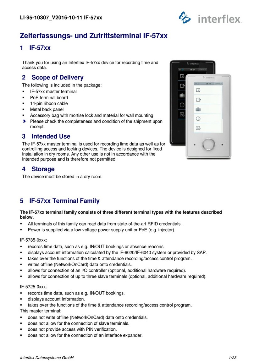
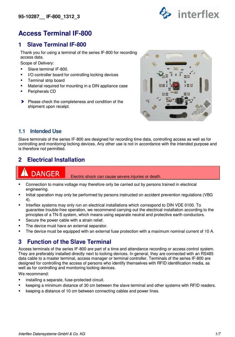
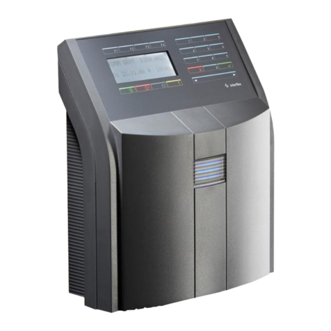
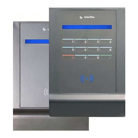
Interflex IF-57 Series User manual

Interflex Datensysteme GmbH 1/8
1 General Information
Thank you for choosing a product from Interflex.
These installation instructions describe the installation of a master terminal. Initial operation is described in
the associated technical manual.
Master terminals of the series IF-5735, IF-5725 and IF-5835 differ in their functionalities:
IF-5735-0xxx IF-5725-0xxx IF-5835-0xxx
displays accounts calculated by
the IF-6040 time
recording/access control program
or provided by SAP
displays account information displays accounts calculated by the
IF-6040 time recording/access
control program or provided by
SAP
writes offline (NetworkOnCard)
data onto credentials does not write offline
(NetworkOnCard) data onto
credentials
does not write offline
(NetworkOnCard) data onto
credentials
allows for connection of an I/O
controller board (optional,
additional hardware required)
does not allow for the connection
of an I/O controller board
allows for connection of up to 3
slave terminals (optional,
additional hardware required)
does not allow for the connection
of slave terminals
provides access with PIN
verification does not provide access with PIN
verification
Commissioning via IF ServiceApp
or SHH console Commissioning via IF ServiceApp
records time data, such as e.g. points in time, IN/OUT bookings and absence reasons
reads current RFID credentials
Power supply via low-voltage supply unit or Ethernet (PoE)
These installation instructions apply both to terminals connected to the IF-6040 system via WLAN and to
terminals connected via Ethernet.
The two types are only distinguished, if necessary.
1.1 Scope of delivery
The package contains:
Master terminal IF-57xx / IF-5835
PoE connector
14-pin ribbon cable
Metal back panel
Accessory bag with mortise lock and material for wall mounting
Check the completeness and condition of the goods immediately upon receipt.
Report any damage caused during transport immediately.
1.2 Technical specifications are subject to change without notice
All information contained in this documentation is accurate at the time of printing. All specifications are
subject to change without notice. The brand names and trademarks specified in this documentation are
protected by commercial and patent laws.
95
-
10430
IF
-
57xx and
IF
-
5835 Master Terminals 2020
-
05
-
19
Installation Instructions for IF-57xx / IF-5835 Master Terminals

Interflex Datensysteme GmbH 2/8
1.3 Target group
This document is solely intended for experts and people trained in electrical engineering.
Only perform the actions described in this document if you belong to this target group.
1.4 Safety
1.4.1 Symbols used
Warnings warn against hazards that may arise when using the devices described in the document. The
hazard levels can be identified by the signal word:
Signal word Description
Indicates a hazard that may result in severe personal injury or even death if
proper precautions are not taken.
Identifies a hazard that may result in minor or medium personal injury if
proper precautions are not taken.
Indicates a hazard that may result in property damage if proper precautions
are not taken.
1.4.2 General safety instructions
§§
Danger to life due to electric shock
People can be seriously hurt or killed through physical contact with live parts (e.g. 230 V~).
Make sure that you cannot touch live lines during installation.
Switch off the power supply of the devices.
Please observe the applicable safety regulations and take all precautionary measures to ensure safe
installation.
Damage due to electrostatic discharge (ESD)
Electrical components and modules can be damaged by only slight, hardly noticeable electrostatic
discharge (ESD) without this becoming immediately obvious. ESD damages result in malfunctions and
even failure of the product.
Make sure that effective protective measures against electrostatic discharge are in place when
working on the open device.
§§
1.4.3 Intended use
Master terminals of the IF-57xx and IF-5835 series are used for recording time data and controlling access
and locking devices.
The terminals are designed for fixed installation in dry rooms. Any other use is not in accordance with the
intended purpose and is therefore not permitted.
Modifications to the terminals are not permitted.

Interflex Datensysteme GmbH 3/8
1.5 Cable lengths and cable types
Cable Function Max. Length Recommended Cable Type
230 VAC power supply to the optional power
supply unit - 3 x NYM 1.5 mm²
Low-voltage cable for supplying power to the
terminal - J-Y(ST)Y 4 2 0.6 mm² or
Flex JZ 3 0.75 mm²
Ethernet/patch cable with/without PoE hub/switch
to the device 100 m Ethernet twisted pair cable (Cat5)
Ethernet/patch cable from hub/switch to the device 100 m Ethernet twisted pair cable
Flexible patch cable (Cat5)
RS485 network cable 1200 m J-Y(ST)Y 4 2 0.6 mm²
Cable lengths: The specifications indicate the maximum permitted cable lengths that guarantee reliable
function.
Cable types: Install only data and control cables with cable shielding, e.g. cable type J-Y (ST) Y or lines
of category 5.7.
To ensure trouble-free operation, we recommend the use of shielded cables.
Operation is also possible with unshielded cables. In case of transmission problems, you will have to
examine the reasons in each individual case. Shielded cables may have to be provided for the
corresponding device.
1.6 Abbreviations
The following abbreviations are used in this document:
Abbreviation Description
AC Alternating Current
BLE Bluetooth Low Energy
CIDR Classless Inter-Domain Routing
DC Direct Current
DIP switch Switch in IC design, connections in two rows (Dual In-line Package)
EMC Electromagnetic compatibility
ESD Electrostatic discharge
GND Ground
IEEE Institute of Electrical and Electronics Engineers
NC contact Normally closed contact
NO contact Normally open contact
PoE Power over Ethernet
RFID Radio-Frequency Identification
SH Shield
SSH Secure shell

Interflex Datensysteme GmbH 4/8
2 Mounting the Terminal
2.1 Installation site
Please observe the following recommendations:
Permitted ambient conditions for the terminal
Minimum distance of 10 cm between the connecting cables and the nearest power lines
Recommended installation height: 1250 mm.
Minimum distances between RFID and BLE devices
If several RFID devices are mounted too close together, mutual interference may occur. Thus, the following
minimum distances must be maintained:
The minimum distance for back-to-back installation depends on the nature of the wall in between.
Please make sure that all BLE devices within range are recognized and that respective doors are opened
(according to the permission) when the "auto-booking" function is enabled.
2.2 Fastening the Back Panel of the Housing
The following figure shows the back panel of the housing and its side view with appliance case and mounted
terminal.
3 bore holes for wall mounting
Threaded bushing for fastening an optional 24 V interface (75-5735-0004)
Threaded bolt for securing the PoE connector
Threaded bushing for fastening an optional I/O controller board (75-700-0141)
Bore holes for mounting via appliance case
Plain washer
Flush box
Recommended installation height: 1250 mm

Interflex Datensysteme GmbH 5/8
Fastening the back panel of the housing directly to the wall
Fasten the back panel of the housing only to an even surface.
If the cables are to be surface-mounted, a spacer is required.
Screw the back panel of the housing to the wall through the holes using the three screws provided.
Fastening the back panel of the housing via an appliance case
If you are using an appliance case, you will need the two washers (shown in the figure) to prevent the back
panel of the housing from being bent.
Screw the back panel of the housing to the wall through the holes and the washers using the two
screws provided.
2.3 Mounting and connecting the PoE connector
Back panel of housing
Network cable
Screws for fastening the PoE connector to the back panel of
the housing
Flat conductor cable
Screw the PoE connector to the threaded bolt on the back panel of the housing using both screws
provided .
Insert the network cable into the cutout of the metal back panel and plug the RJ45 plug into the
socket of the PoE connector.
To power the PoE connector externally (if necessary), connect the three wires of the cable to the AC/DC-
and AC/DC+ terminals and the protective ground to the PE terminal. Functional grounding is ensured via
the RJ45 connector and the hub/switch.
The PoE connector is connected to the terminal via a 14-pin ribbon cable with interference suppression
cores between the mainboard and the PoE connector.
Plug in the 14-pin ribbon cable as shown in the figure.

Interflex Datensysteme GmbH 6/8
3 Integrating Terminals into the System
Server with time recording software, e.g. IF-6020 or IF-6040
IF-57xx / IF-5835 master terminals
External power supply (optional) with a mounting rail power supply unit and fuse protection
PoE device: Switch or power injector
Interface expander
I/O controller board for direct connection to slave terminals
IF 800 slave terminal
Connect the components as shown in the figure.
As opposed to LEGIC and MIFARE reading technologies, the reading unit with SimonsVoss Active
Technology (SVP) must be configured for the respective customer settings.
Points to note on the compliance with the required EMC values
Check if there is functional grounding on the PoE device. Ground PoE devices without functional
grounding via existing soldering lugs or screw terminals.
Observe the notes under Cable lengths and cable types (on page 2).
Observe the standards applicable to electrical installations.
The device may only be operated via electrical systems that comply with current national standards.

Interflex Datensysteme GmbH 7/8
4 Technical Specifications
Electrical Data
Nominal voltage 18 to 24 VAC/DC
Power supply via Ethernet (PoE) PoE device IEE 802.3 of power class 0 (up to 13 W).
Power consumption Approx. 13 VA
Interfaces
Data interface Ethernet network connection with SSH
TTL service interface
Reader
Reader type Depending on the order, RFID technology: MIFARE,
LEGIC or SVP (SimonsVoss Active Technology)
Operating unit
Display 4.3 inch color display; resolution of 480 272 pixels
Touch Capacitive
General Data
Ambient temperature: +4°C to +40°C
Humidity Max. 95 %, non-condensing
Degree of protection IP30 (with concealed wiring)
Dimensions (W x H x D) 163 87 45.8 mm
Housing material Thermally tempered clear glass on a polycarbonate body
Weight 0.4 kg
Installation type Screw fastening (surface-mounted)
Cable feed Flush-mounted (or surface-mounted using spacers)
Color Black / white
Storage In a dry place
5 EU Declaration of Conformity
Interflex hereby declares that the products comply with the directives 2014/30/EU,
2014/35/EU and 2011/65/EU.
You can download the complete EU Declaration of Conformity on our website in the
Media / Download section: www.interflex.de/en/index.html
6 Disposal
Once its service life comes to an end, the device must be disposed of properly as
electronic waste. You can dispose of the device yourself or return it to the supplier.

Interflex Datensysteme GmbH 8/8
7 Open Source Program Packages
This product uses program packages that are subject to Open Source License Terms (e.g. GNU GPL
License Version 2).
Upon request and for a charge no more than your cost of physically performing source distribution, Interflex
offers to provide you with a medium customarily used for software interchange containing a complete
machine-readable copy of the source code of the programs used. This offer is valid for a period of three
years, starting on the date the product is purchased.
Copyright © 2020 Version Date: May 19, 2020
Interflex Datensysteme GmbH
Zettachring 16, D-70567 Stuttgart, Germany Tel.: +49 (0711) 1322 0
www.allegion.com
Other manuals for IF-57 Series
1
This manual suits for next models
3
Table of contents
Other Interflex Touch Terminal manuals
Popular Touch Terminal manuals by other brands
IVC Displays
IVC Displays MT-606S user manual
Newland
Newland NLS-NQuire300 user guide

HP
HP HP700/92 user manual
ZETRON
ZETRON 640 DAPT XTRA Installation and repair guide

Beijer Electronics
Beijer Electronics X2 extreme 7 12V CO installation manual
Protech Systems
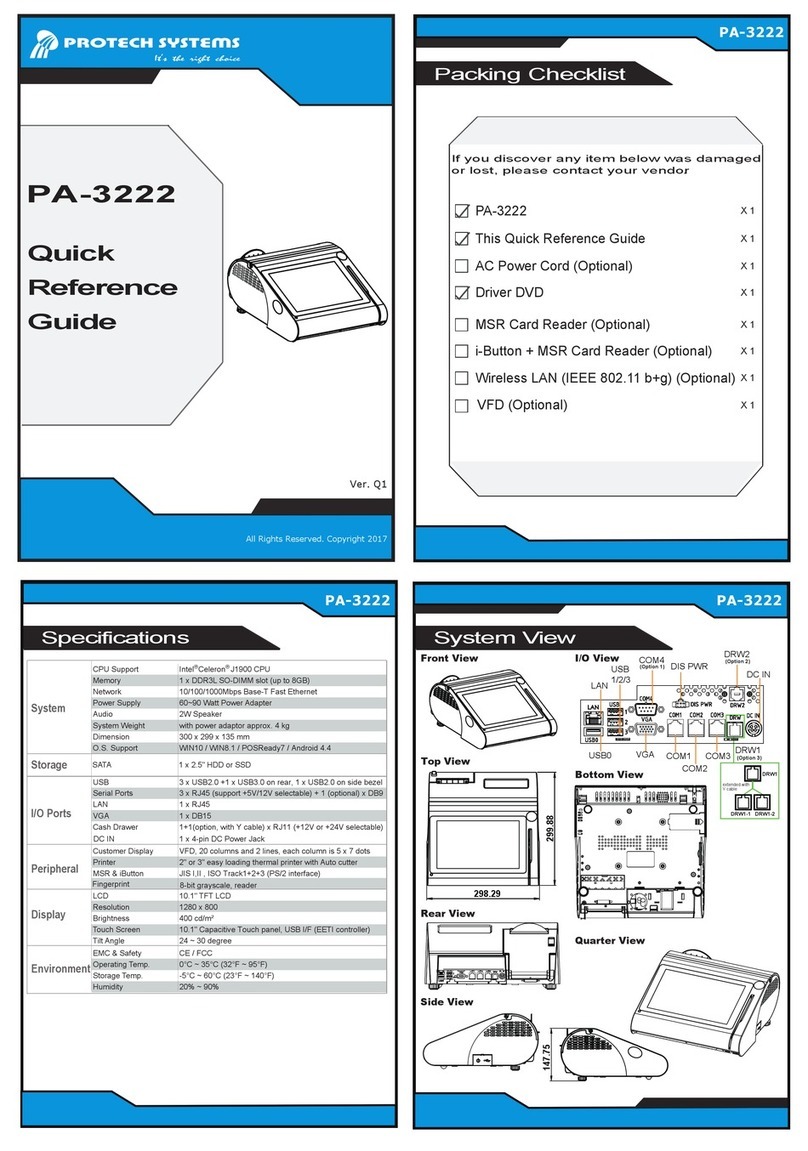
Protech Systems PA-3222 Quick reference guide
