Interflex IF-810 User manual

Interflex Datensysteme GmbH 1/8
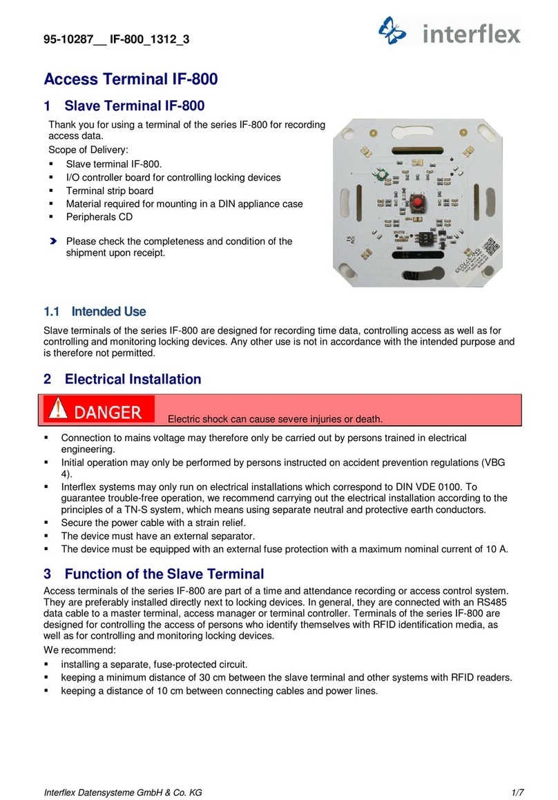
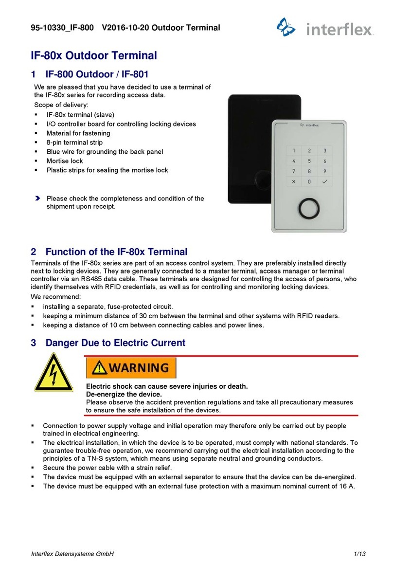
1 IF-810 or IF-811 Terminal (Slave)
Thank you for choosing an Interflex system. With an IF-810 or
IF-811 terminal (slave), you have purchased a reliable device for
capturing access data.
Furthermore, with an IF-811 terminal (slave), you can also enter
your PIN via a membrane keypad.
Scope of delivery:
IF-810 or IF-811 terminal (slave)
Terminal strip board
Mortise lock
Material for wall mounting
Please check the completeness and condition of the shipment
upon receipt.
2 Intended Use
Slave terminals of the IF-810/IF-811 series are devices for capturing access data as well as for writing to
RFID credentials. Furthermore, with an IF-811 terminal (slave), you can also enter your PIN. The device is
designed for indoor and outdoor use (see note). Any other use is not in accordance with the intended
purpose and is therefore not permitted.
3 Assembly and Installation
95-10326_V2016-10-20 IF-810/IF-811

Interflex Datensysteme GmbH 2/8
3.1 Cables and Cable Types
No.
Max. Length Cable Cores
1 BUS cable from controller to terminal (slave) installed furthest away 1,200 m 4 x 2 x 0.6 mm²
1a Branch cable from bus to installation site of terminal (slave) 100 m 4 x 2 x 0.6 mm²
2 110/ 230 V mains cable to transformer or DC power supply unit
2a Low voltage cable to terminal board (3) 4 x 2 x 0.6 mm²
We recommend:
installing a separate, fuse-protected circuit.
supplying operating voltage via a separate cable (2a) to avoid interference.
keeping a minimum distance of 30 cm between the slave terminal and other systems with RFID readers.
keeping a distance of 10 cm between connecting cables and power lines.
The following installation procedure has been proven and tested:
1. Install the cables.
2. Install the power supply.
3. Mount the back panel of the IF-810/IF-811. If the terminal is to be used for access control, an I/O
controller board must also be mounted in a secured area.
4. Set the address.
5. Close the housing.
6. Put the IF-810/IF-811 into operation.
3.2 Shielded Cables
To guarantee trouble-free operation, we recommend the use of shielded cables.
Operation, however, is also possible with unshielded cables. Data transfer problems must be examined on a
case-by-case basis. Where necessary, a shielded cable must be used for the corresponding devices.

Interflex Datensysteme GmbH 3/8
3.3 Open/Close Housing
The back panel of the housing (6) and the housing cover (8) are held together with internal latches and
secured with a mortise lock (3).
1 IF-810/IF-811 terminal (slave) 5 Terminal strip board
2 Tool for opening the IF-810/IF-811 terminal (order no. 50-10137) 6 Back panel of housing
3 Mortise lock 7 Connecting cable
4 Locking latches 8 Housing cover
Open:
1. Unlock the mortise lock and pull it down and out.
2. Insert the pins of the tool (2) into the housing from the bottom and, by doing so, push open the two
internal latches.
3. With the latches unlocked, swivel up the housing cover.
4. Disconnect the connecting cable and remove the housing cover.
Close:
1. Plug in the connecting cable at the respective board.
2. Tilt the housing cover and hook it onto the upper edge of the back panel of the housing.
3. Hinge down the housing cover until you hear the latches in the back panel of the housing lock into place.
4. Secure the housing by means of the mortise lock.

Interflex Datensysteme GmbH 4/8
3.4 Mounting
1 Back panel of housing with terminal board 4 Rubber seal
2 Recommended cable feed: Flush-mounted 5 Plain washers
3 Installation cable 6 Fastening screws
The back panel of the housing (1) must not warp when being screwed down.
The IF-810/IF-811 terminal (slave) can be installed in dry or humid environments (IP43). Installation is
performed on flat walls or pillars, e.g. next to doors, using the materials included in delivery. The I/O board is
installed in a secured area, e.g. into an installation box from Hensel or a DIN appliance case.
The sealant (4) used evens out unevenness in the wall and makes a seal to the wall. This sealant allows for
installation in humid rooms.
If the mortise lock (IP54) is sealed, the device can be installed outdoors.

Interflex Datensysteme GmbH 5/8
3.5 Hardware Address Setting
In order to specify the device address, up to 4 address switches must be set to the correct position
on the MPU board.
Before setting the switches, check the bus address range. Addresses may not be assigned twice.
Set address 1 for the first slave terminal, address 2 for the second slave terminal, and so forth.
For the connection to a master terminal, set address 2 for the first slave terminal, and so forth.
Switch
4
3
2
1
Address 1 OFF OFF OFF OFF (not required if connected to a master terminal)
Address 2 OFF OFF OFF ON
Address 3 OFF OFF ON OFF
Address 4 OFF OFF ON ON
Address 5 OFF ON OFF OFF
Address 6 OFF ON OFF ON
Address 7 OFF ON ON OFF
Address 8 OFF ON ON ON
3.6 Wiring
Power supply
Power can be supplied:
via a 12 VAC - 24 VAC power transformer.
via a 12 VAC - 24 VAC low-voltage power supply unit.
via an IF-79 I/O BUS panel (max. 100 m).
Connecting the BUS cable
The IF-810/IF-811 terminal is connected to BUS1, BUS2 or BUS3 of a controller.
Connecting the I/O controller board
The I/O controller board is used for controlling electric actuators. If access control is not required, the I/O
controller board can be omitted. In that case, connection takes place directly on the terminal board using a
cable of up to 100 m length.

Interflex Datensysteme GmbH 6/8
The IF-810/IF-811 terminal requires functional grounding in order to comply with the
EMC threshold values. The line shield is connected to terminal 8 (PE) on the terminal board as well as to
terminal 4 or 10 on the I/O controller board.
3.7 Controlling Locking Devices with I/O Controller Board
1 I/O controller board (accessories) 2 Power supply connection
1a Br. 4 jumper selection 3 Data cable connection
1b Br.1 relay contact in NO or NC position 4 Connection of electric control element (door opener)
1d Br.5 plug contact for anti-tamper switch 5 Connection of door sensor, handle or NC contact

Interflex Datensysteme GmbH 7/8
The I/O controller board allows for access control. The board can switch electric door
openers up to max. 30 V 2 A via an NO or NC contact. It must be separated from the IF-810/IF-811 terminal
and installed in a secured area, e.g. in a Hensel installation box (no. 78-700-0146) or a DIN appliance case.
In order to prevent malfunction and manipulation, the I/O controller board may not be installed in the housing
of an IF-810 or IF-811 terminal.
3.7.1 Circuit Examples
Power supply (2)
The IF-810/IF-811 terminal can be supplied with 18-24 V AC/DC via the I/O controller board.
Connection of RS485 data cable (3)
The RS485 data cable is connected to terminals 5, 6 and 7. The data cable may have a max. length of 1200
m. If a spur line is connected to the data line, the length of the spur line may not exceed 100 m.
Connection of a control element (4)
An actuator, shown as a door opener in the figure, is connected to terminals 8 and 9. The actuator is
controlled by the relay of the I/O controller board and can switch a maximum of 30 V and 2 A. Via the bridge
(1b), the relay contact can be changed from normally open (NO) to normally closed (NC). If two relay outputs
are required, a further I/O controller board is needed.
Connection of sensors (5)
Two sensors can be connected to the I/O controller board. Usually, one door contact and one door opener
are connected. If more than two sensors are required, a further I/O controller board is needed. The bridge
(BR4) must then be removed on the second I/O controller board.
To avoid interferences, use shielded cables for the connection between the I/O
controller boards and the terminal.
3.8 Connecting two I/O controller boards
3.9
For technical reasons, the total length of the COM cable is limited to 100 m. The length of the COM cable is
to be reduced as in the example to ensure that a total length of 100 m is not exceeded. The bridge (4) on I/O
controller board 2 must be removed.

Interflex Datensysteme GmbH 8/8
4 Accessories
The following components can be ordered as accessories:
I/O controller board, order number: 75-700-0141
Power transformer PSU 230 / 20 VAC 1.5 A, order number: 41-10106
Release lever for housing, order number: 50-10137)
5 Technical Specifications
Power Supply
Low-voltage 12-24 V AC / DC (measured directly at the terminal)
Power consumption Max. 4 VA
Protection Protection via PTC resistor
Interfaces
Interface to parent devices RS485, 9600/ 19200 baud (automatic configuration)
Reader LEGIC or Mifare / Proxif (depending on the order)
Read range Up to 50 mm, depending on the reader type
Inputs for sensors (optional) 2 (4 with 2 I/O controller boards)
Output relay (optional) 1 (2 with 2 I/O controller boards)
Switching power 30 V, 2 A
User information Luminous bar with LEDs (blue, green, red)
Data entry As opposed to IF-811, the IF-810 terminal is not equipped with a
keypad.
The IF-811 terminal is equipped with a numeric membrane keypad.
Device Protection
Protection category III
Degree of protection IP43 (IP54 after sealing the mortise lock)
General Data
Ambient temperature -25°C to +55°C
Humidity Max. 95%, non-condensing
Product safety EN 60950-1
Compatibility (EMC) EN 300330-1/2, EN 301489-1/3, CE
Dimensions (H x W x D) 150 x 105 x 42 mm
Weight Approx. 0.4 kg
Housing material Plastic
Installation type Surface mounting
Cable feed Flush-mounted
6 Disposal
Once its service life comes to an end, the device must be disposed of properly as
electronic waste. The owner can dispose of the device himself or return it to the
supplier.
Copyright © 2016 Version Date: October 31, 2016
Interflex Datensysteme GmbH
Zettachring 16, D-70567 Stuttgart, Germany Tel.: +49 (0711) 1322 0
Internet E-Mail: interflex.info@allegion.com Websites: www.interflex.de www.allegion.com
This manual suits for next models
1
Table of contents
Other Interflex Touch Terminal manuals
Popular Touch Terminal manuals by other brands
Mercury
Mercury 2+ user manual
RoamWiFi
RoamWiFi R9 user manual

Blue Bamboo
Blue Bamboo H50 Quick installation guide
Vector
Vector POS TOUCH 12 WIDE Notes on safety and installation

Korea Creadic Life Co., Ltd.
Korea Creadic Life Co., Ltd. AD-POP wireless user manual
NCR
NCR Ordermang 9900 Hardware user's guide
