2 / 8 P/N 1073498A• REV 01.01 • ISS 27AUG18
Wiring
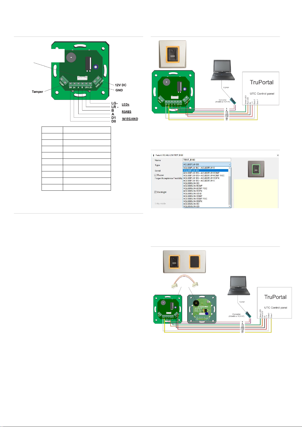
Figure 2: Wiring
Connecting biometric readers to controllers
Figure 3: Wiring instructions
•Connect the lines D0, D1, LR-, LG-, GND and +12V to the
TruPortal controller.
•Connect the RS485 Line (A, B) to the ACL800FL-CONV-
W converter.
Connect the converter and the PC to the LAN.
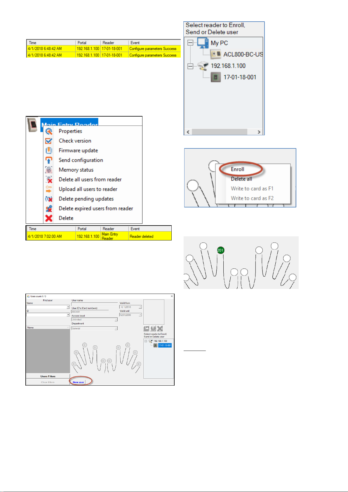
•Fingerprint enrollment is done from the ACL800
BioManager software. Connection between the biometric
readers and the PC must be established.
•The biometric readers communicate with each other with a
RS485 and with the ACL800 BioManager software through a
converter.
•The RS485 line should be configured in the form of a
daisy chain, NOT in a star topology. Keep the stubs from the
RS485 backbone as short as possible (not more than 5
meters)
•Only one converter per installation is needed for maximum
of 31 connections, not per reader.
•The 120 Ohm end-of-line resistors are necessary and
provided with the products.
Wiring the biometric reader only
Figure 4: Wiring biometric reader only
In the ACL800 BioManager software, in reader’s properties, for
the “type” of the reader, select “ACL800FLW-BS”
Figure 5: ACL800 BioManager
Wiring biometric reader and proximity
reader
Figure 6: Wiring biometric reader and proximity reader
1. Connect both devices with the cable provided.
2. Connect ACL800FLW-BS to the controller. The proximity
reader is not connected to the controller.
3. In the software, in reader’s properties, for type of the reader
select ACL800FLW-BS + ACL800FLW-RDPX
Connection to proximity
reader or keypad